 Yueqi Wang1
 Yi Xie
 Yangjun Zhang
- 1State Key Laboratory of Automotive Safety and Energy, School of Vehicle and Mobility, Tsinghua University, Beijing, China
- 2College of Mechanical and Vehicle Engineering, Chongqing University, Chongqing, China
Battery performance and lifespan are greatly dependent on its temperature, and a good battery thermal system (BTMS) can make the battery work at its favorable temperature range, improve its electrical performance, and extend its lifespan. Due to the high heat conductivity and large surface area of flat heat pipe (FHP), the FHP-based BTMS can quickly remove the heat produced by the battery and improve the temperature homogeneity among cells in the pack. In this study, the FHP is applied to the BTMS, and the influence of its structure on the battery thermal dynamics is studied. Firstly, a coupled thermal model for the FHP-based BTMS is established and verified by the experiment. This model integrates the resistance-based thermal model of the battery and FHP model based on the thermal resistance network. Then, the effect of the structure parameters of FHP such as the thickness, porosity, and particle diameter of sintered wick on the thermal performance of the battery is investigated. According to the results, the temperature variation among battery cells rises significantly when the dimensionless thickness of the wick is greater than 0.7. Moreover, the change of the porosity and particle diameter of the wick results in a nonlinear development of the wick thermal resistance which finally changes the heat conductivity of the FHP and battery temperature. Finally, a neural network model (NNM) is used to establish the relationship between the FHP parameters and battery thermal performance for optimizing the BTMS structure. According to optimization result, the optimized FHP can keep the maximum battery temperature below 40°C at a discharge rate of 2C and reduce the temperature variation in the battery by 7.4%.
1 Introduction
Nowadays, electric vehicles have been developed rapidly due to energy conservation and emission reduction policies. Lithium-ion battery is considered to be one of the most appropriate power sources for electric vehicles with their high energy/power density, low self-discharge rate, and long lifespan (Shi et al., 2021). Its overall performance directly affects the operation stability and cruising range of electric vehicles (Abada et al., 2016). Temperature is a crucial factor influencing the overall performance of lithium-ion batteries (Rao and Wang, 2011; Cen and Jiang, 2020). Higher temperature may cause the decomposition of the electrode and electrolyte, which finally leads to thermal runaway or explosion of batteries (Feng et al., 2015; Dai et al., 2021). Besides, temperature differences among battery cells also need to be controlled, since a large temperature difference aggravates the aging process of batteries and severely influences the lifespan and performances of batteries (Park and Jung, 2013; Zhang et al., 2017). With the urgent demand of electric vehicles towards higher battery power density and charging-discharging rate, a proper battery thermal management system (BTMS) is of great significance to control the temperature rise and reduce the temperature difference of batteries. It is generally suggested that the optimal temperature range of lithium-ion batteries is 25–40°C and the temperature difference should be limited below 5°C (Ye et al., 2015; Panchal et al., 2016).
Thus far, diverse cooling techniques have been conducted for BTMS including air cooling, liquid cooling, cooling based on phase change principle, etc. (Kim et al., 2019). Air cooling is now widely used owing to its simple and lightweight structure with low cost (Hong et al., 2018). Its cooling capacity can be improved by optimizing the structure of air channels (Chen et al., 2019), battery layout (Yang et al., 2015), and control strategies (Mahamud and Park, 2011). However, due to the low heat capacity of air, an air cooling system has a low heat transfer coefficient and poor heat dissipation effect, especially under high charge/discharge rate. Liquid cooling is more effective compared to air cooling because liquid coolants have a high heat transfer coefficient. Many researchers focus on the fluid channel design and coolants' thermal property improvement to enhance the performance of liquid cooling (Xu and He, 2014). However, the system components such as coolant, pumps/compressors, and tubing increase the weight of the system and the risk of leakage (Behi et al., 2021a). Phase change material (PCM) is booming in the BTMS field recently, but the intrinsic lower thermal conductivity of PCM causes the delay of the heat dissipation rate from a power battery system (Lin et al., 2015).
Heat pipe is a kind of high-efficiency heat transfer element which bases on phase change principles. It has superior thermal conductivity and temperature uniformity capability (Reay et al., 2014; Aswin Karthik et al., 2020). Heat pipe has received much more attention on BTMS in recent years. Researchers combined heat pipe with other cooling methods to improve battery thermal performance (Dan et al., 2019a; Wang et al., 2019; He et al., 2022). For example, Wang et al. (Wang et al., 2015) used L-shaped heat pipes to explore the influence of heat generation power on heat dissipation efficiency. The proposed method is able to keep the battery surface temperature below 40°C if the battery heat generation is less than 10 W/cell. Rao et al. (Rao et al., 2013) conducted a research on the thermal performance of sintered heat pipe-based BTMS. The battery maximum temperature could be kept below 50°C under the battery heat generation rate less than 50 W. Liang et al. (2018) placed straight heat pipes between battery cells to study the effects of coolant flow rate, coolant temperature, and control strategies on heat dissipation efficiency. Chen et al. (2021) combined heat pipes with PCM and verified it can effectively reduce the temperature difference in the battery pack. The maximum temperature difference in battery pack is decreased by 30% after the optimization on PCM thickness distribution. These related studies have verified the feasibility of heat pipes in BTMS. Compared with the conventional circular heat pipe, flat heat pipe (FHP) has a larger contact area with battery, which efficiently advances temperature uniformity and optimizes the system layout. Tran et al. (2014) explored the influence of different flat heat pipe inclination angles on the thermal performance of lithium-ion batteries. The cell temperature can be kept below 50°C under a small range of tilt angles and an average heat flux density. Jouhara et al. (2020) placed a flat heat pipe under a battery module, and the system was cooled by water flow. The maximum cell temperature was maintained below 35°C and the temperature uniformity was kept below 3°C at 4C discharge rate. Behi et al. (2021b) designed a sandwiched configuration of the heat pipe cooling system combined with forced convection. The temperature variation of cells can be controlled under 40°C at 8C discharging rate. The results show that flat heat pipe combined with air or liquid cooling shows great effect on battery thermal management.
Researchers also carried out related studies on the simulation analysis of the flat heat pipe in BTMS. Behi et al. (2020; 2021b) established a computational fluid dynamic BTMS model using COMSOL Multiphysics® to analyze the thermal performance of battery cells under various transient boundary conditions. Zhang and Wei (2020) developed a numerical model of flat heat pipe coupled air cooling in BTMS and compared the simulation results to air natural convection and aluminum plate cooling. Xu et al. (2019) combined flat heat pipe with liquid cooling and simulated to analyze the enhanced heat conduction effect under different discharge rates. Yao et al. (2021) proposed a novel flat heat pipe and refrigerant-based BTMS coupled with an air-conditioning system for a battery module. The battery temperature distribution is numerically investigated under various ambient temperatures and battery heat generation rates. In the abovementioned studies on flat heat pipe simulation in BTMS, as the heat pipe is slightly longer than batteries, it can be considered as an isothermal conductor with constant thermal conductivity (Deng et al., 2013). Furthermore, in order to reduce the computational time, some researchers have applied the one-dimensional equivalent thermal network model of the heat pipe into BTMS simulation (Dan et al., 2019b). Greco et al. (2014) presented a simplified thermal network model of heat pipe to predict the thermal behavior of a prismatic lithium-ion battery cell. The porous media in the heat pipe was taken into account. Gan et al. (2020) and Liang et al. (2019) proposed the thermal resistance network heat pipe model on a battery module consisted of cylindrical cells. The relationship between the thermal resistance and the operating temperature was considered. The above research shows that applying thermal resistance network heat pipe model to BTMS simulation analysis is gradually receiving attention from researchers.
Considering the past studies, researchers have verified the effect of heat pipes applied to battery thermal management through simulation or experiments, and they have shown many good results. These researches mainly focus on the configuration of the BTMS system and demonstrate the influence of operating conditions on battery thermal performance. Nevertheless, these studies still have some shortcomings which need to be improved. Firstly, the thermal model of FHP in BTMS should be improved. In the researches above, some researches (Xu et al., 2019; Zhang and Wei, 2020; Yao et al., 2021) regarded the thermal conductivity of FHP to be constant. However, the thermal conductivity of FHP is dependent on the temperature and cannot be regarded as constant in the process of battery operating conditions (Reay et al., 2014). Some researches (Gan et al., 2020) take the FHP thermal resistance into account, but the heat source of FHP is a battery cell rather than battery module. Thus, the simplifications of the heat source to be single and FHP thermal conductivity to be constant evoke the prediction uncertainty of temperature distribution in BTMS. Secondly, structural parameters of the heat pipe, such as wick thickness and wick porosity, have a great influence on its internal flow and heat transfer process and then affect its heat transfer capacity, which is a factor that cannot be ignored when considering the thermal performance of batteries. Few studies have considered the influence mechanism of heat pipe structural parameters on the thermal characteristics of the battery, which cannot make an appropriate guidance on the heat pipe structure design for BTMS. Thirdly, the optimization of FHP structural parameters has not yet been considered in BTMS design to improve the temperature thermal performance of batteries. Therefore, it is necessary to explore the effect mechanism of heat pipe structural parameters on thermal performance of batteries, which may lay a foundation for the optimization design of heat pipe.
In the present article, we utilize flat heat pipe for heat dissipation of prismatic batteries. An FHP-based thermal management system for the battery module is proposed. Compared with the existing studies, there are three contributions made in this paper. Firstly, a parameterized model for FHP-BTMS is established considering multi-heat sources of batteries and each heat transfer thermal resistance unit of FHP. Secondly, the impacts of FHP structural parameters, including wick thickness, wick porosity, and particle diameter, on battery thermal performance are investigated. Thirdly, an optimization design method towards structural parameters of FHP is carried out in order to improve the battery thermal performance.
2 Numerical Models
An FHP-based BTMS system is displayed in Figure 1A, including relevant dimensions. The following 1D thermal resistance network model is based on this BTMS system. Similar to a liquid cooling system, the FHP is placed at the bottom of the battery module. The battery module consists of 12 battery cells in three parallel and four series. The generated heat of batteries under charging or discharging conditions is directly transferred to the FHP. The working fluid in the capillary wick absorbs the heat by phase change and conducts heat to the condensation section. Finally, the heat is taken away by cooling fins at the condensation section of FHP. The inside structure of FHP and FHP working schematic is presented in Figure 1B. A thermal pad is arranged between batteries and FHP to reduce the contact thermal resistance. In order to ensure the temperature uniformity along with the height of the battery module, aluminum sheet is inserted between every two adjacent batteries. For this whole thermal management system, the entire heat transfer process includes the heat transfer performance of batteries and FHP. The thermal performance of batteries is influenced by a combination of these two aspects. Therefore, it is of great significance to establish the heat generation model of batteries and the heat transfer model of the FHP to clarify the influence the mechanism between them.
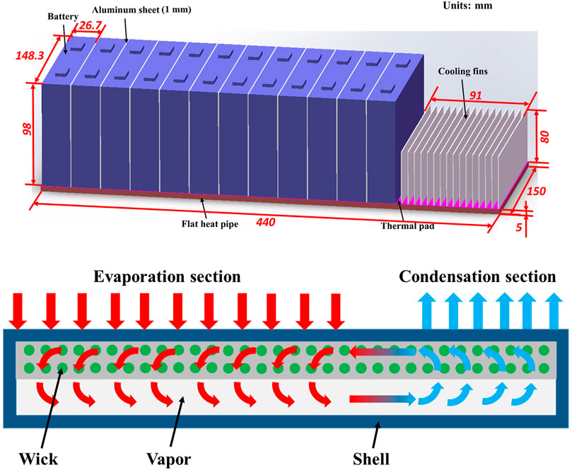
FIGURE 1. (A) Schematic of BTMS based on flat heat pipe. (B) Inside structure and schematic representation of an FHP.
2.1 Battery Heat Generation Model
In this study, a module consists of 12 prismatic batteries is used for analysis. The parameters of a battery cell are presented in Table 1.
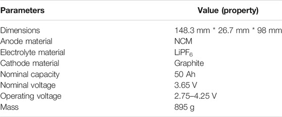
TABLE 1. Parameters of lithium-ion battery cells
The heat generation of cell consists of two primary heat sources which are the irreversible joule heat caused by battery internal resistance and the reversible heat caused by the entropy change, respectively (Thomas and Newman, 2003). It is expressed as presented in the right side of Eq. 1.
where Q is the heat generation rate inside the battery cell; I is the charging or discharging current through the battery; U and Uocv, respectively, denote the terminal and open-circuit voltage of the battery; T is the battery temperature; and dUocv/dT is the battery entropy coefficient. According to Onda et al. (2006) and Inui et al. (2007), Since the irreversible heat could be expressed as I2(Ro + Rp), the heat generation rate in the unit volume (q) could be rewritten as:
where V is the cell volume and Ro and Rp are the ohmic resistance and polarization resistance of the battery, respectively. The values of these two parameters are related to the temperature, SOC, and the current of the battery, and have a non-linear relationship. In this study, the resistance-based battery model is set up to reflect this relationship. The energy equation is solved to obtain the temperature distribution of the battery cell (Yang and Tao, 2006):
where ρ, Cp, and λ are the density, specific heat, and thermal conductivity of the battery. The subscripts x, y, and z are the directions of the x, y, and z axes.
The detailed modeling process and experimental validation of the resistance-based battery model are described in our previous studies (Li et al., 2020).
2.2 FHP Heat Transfer Model
A multi-heat-source thermal resistance network-based flat heat pipe model is adopted to predict the thermal performance of FHP. The heat generated inside the battery is transferred to the shell of FHP through the thermal pad then to the capillary wick and its internal working fluid, enters the vapor channel after phase change, and finally is carried away at the condensation section. The heat transfer process in each step corresponds to a heat transfer thermal resistance, respectively. On the other hand, the heat generation rate of each battery is different and changes with time in the operating conditions. Hence, multiple heat sources are transferred into different positions of vapor core in the FHP. For the proposed FHP, there are 12 heat sources in the battery module, and the thermal resistance network model of FHP is shown in Figure 2. Rsi and Rwi, respectively, represent the heat transfer thermal resistance of the shell and capillary wick of an FHP. Rpci denotes the phase change thermal resistance. Rvi is the generated thermal resistance due to pressure drop along the vapor channel. The expressions of different thermal resistance types are listed as follows, which are derived from continuity, momentum, and energy equations.
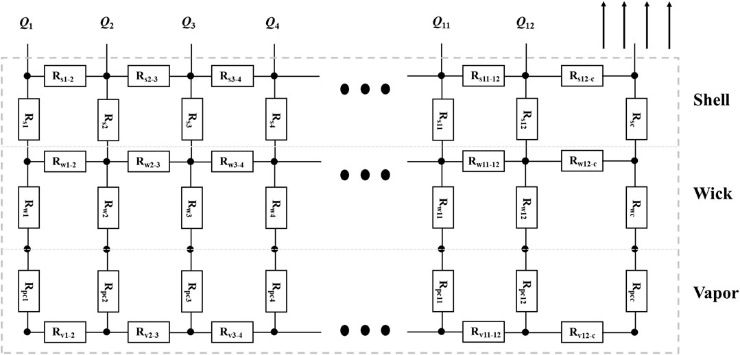
FIGURE 2. Network scheme for a multi-heat-source FHP.
2.2.1 Thermal Resistance of the Shell
The heat is transferred through the shell by heat conduction. The thermal resistance of the FHP shell corresponding to each heat source is calculated from (Poplaski et al., 2016):
where ts and λs denote thickness and thermal conductivity of the shell, and Aei is the area of FHP under each battery cell. In a similar way, the thermal resistance at the condensation section is expressed in Eq. 5 (Poplaski et al., 2016):
where Ac is the area of the condensation section of FHP.
2.2.2 Thermal Resistance of the Capillary Wick
The internal heat transfer process of the capillary wick includes heat conduction and convection of the working fluid. Assuming that the capillary wick is always filled with fluid during the working process of FHP, the thermal resistance can be calculated from Eq. 6 (Poplaski et al., 2016):
where tw is the thickness of capillary wick and λw denotes the equivalent thermal conductivity of the wick. In our previous study (Qian et al., 2020), three-dimensional diffusion limited aggregation models based on the microstructure of the wick are reconstructed, and the equivalent thermal conductivity of the capillary wick (λw) is calculated by Eq. 7:
where λbulk is the solid phase thermal conductivity, lbulk is the phonon mean free path of the solid phase and is related to the porosity of the wick, aw denotes the diameter of contact interface among particles, and dw is the particle diameter of the wick. It is noticeable that the thermal resistance of the wick is mainly influenced by its structural parameters.
2.2.3 Thermal Resistance of Phase Change
The working fluid of the FHP undergoes phase change at the interface between the capillary wick and the vapor channel. Assuming that the heat flux density of the evaporation section has not reached the boiling stage, only evaporation occurs and the evaporation rates are the same. The phase change thermal resistance at the evaporation section can be calculated by Eq. 8 (Poplaski et al., 2016):
where Tv, pv, and hfg are the temperature, pressure, and latent heat of the working medium, respectively; Rgas is the gas constant; and σ is the accommodation coefficient, which is assumed to be 0.03 in this study. The phase change thermal resistance at the condensation section is the same and can be expressed by Eq. 9 (Poplaski et al., 2016):
2.2.4 Thermal Resistance of Vapor Flow
The following assumptions are made in conducting the analyses on the vapor flow in the vapor channel:
(a) The heat transfer and fluid flow are in the steady state.
(b) The vapor flow is incompressible.
(c) The gravity effect is neglected because FHP is operated in the horizontal mode.
(d) The gaseous working fluid has only one-directional velocity component.
The equivalent thermal resistance of vapor flow from the evaporation section to the condensation section is expressed as (Poplaski et al., 2016):
where, μv denotes vapor dynamic viscosity; tv is the thickness of the vapor channel; le and lc, respectively, represent the length of evaporation and condensation section of FHP; and lFHP is the total length of FHP along the heat transfer direction, which is the sum of le and lc (the length of FHP adiabatic section is neglected in this paper).
For the BTMS system in this paper, the main cause of the changes on maximum temperature and temperature difference of the battery cell is the FHP thermal resistance under the same discharging and heat dissipation conditions. As the structural parameters of the FHP changes, its thermal resistance variates correspondingly, which affects the thermal performance of the batteries. For the multi-heat-source FHP presented in this article, the temperature characteristics of each heat transfer unit depend on the effective thermal resistance from the heat source to the condensation section. The heat transfer path and heat transfer thermal resistance is different due to diverse distances between each heat source and the condensing end. Thus, in this study, the effective thermal resistance (Ri,eff) for each heat source is defined as the sum of the thermal resistance of each unit on the heat transfer path from the heat source to the condensation section:
2.3 Coolant Heat Dissipation
In the present study, air cooling was adopted for heat dissipation. In order to enhance the heat transfer capability, a series of fins are placed side by side at the condensation section of FHP which can effectively increase the heat dissipation area. We selected rectangular fins as heat exchangers, whose material is aluminum, the same as shell material. The convection heat transfer coefficient (Hf) between the fin surface and the cooling air is calculated by the following equation (Liu et al., 2016):
where Ref and Prf, respectively, denote the Reynolds number and Prandtl number of the cooling air. λf is the thermal conductivity of the cooling air at the condensation section. sfin, hfin, and tfin, respectively, represent the spacing, height, and thickness of the fins. Hf is mainly influenced by the properties of cooling air and the geometry structures of cooling fins. The key structural parameters of cooling fins are listed in Table 2.
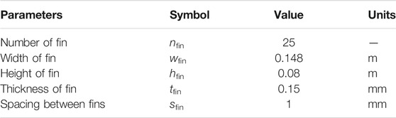
TABLE 2. Structural parameters of cooling fins
2.4 Battery-FHP-Coupled Model
A battery-FHP-coupled model is further established based on the battery heat generation model and FHP thermal resistance network model above. It is divided into three parts, including the battery module, FHP module, and heat dissipation module. The basic idea of the coupling method is shown in Figure 3. The heat generation rate of each battery at each time step can be obtained according to the current, SOC, and temperature and is input to the battery module as an internal heat source. The temperature of each FHP and battery node can be obtained by solving the energy equation for each control volume. It is further used to calculate the internal resistance and heat generation rate of the battery at the next time step. Meanwhile, the thermal resistance of FHP which varies with temperature can be obtained. The value of the thermal resistance of each heat transfer unit can be further applied to the solution of the system energy balance equations at the next time step. The thermal performance of the batteries can be obtained by repeating the calculating process mentioned above. The battery-FHP-coupled model is constructed based on MATLAB/Simulink software.
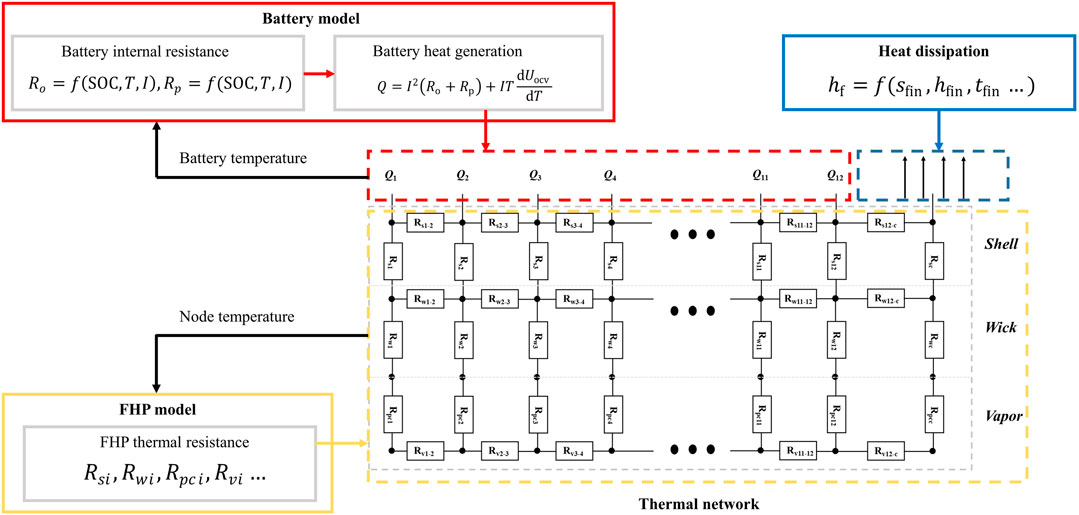
FIGURE 3. Coupling method of the battery model and the FHP model.
3 Model Validation
In order to validate the battery-FHP-coupled model, the calculation results are compared with the following experimental data. In the present study, an aluminum FHP is designed and fabricated. Considering the working temperature and compatibility for aluminum, acetone is selected as the working medium and the filling ratio is 50%. The design parameters of FHP are listed in Table 3.
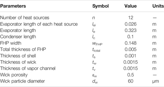
TABLE 3. Key structural parameters of FHP
The experimental devices for the system are shown in Figure 4. They consist of an FHP mounted with rectangular fins, a battery module, a battery tester, and a temperature measurement and acquisition system. The battery module which contains 12 lithium-ion battery cells is arranged in parallel on the surface of the FHP. The battery tester (Digatron EVT300-0600) is used to charge the cell and provide the external load to the battery module. Moreover, it also collects the current and voltage when the battery cells are in charging or discharging conditions. The relative error of the battery tester is less than 0.1% of the measurements. The surface temperature of the battery cells is tested by the K-type thermocouples and the testing error of the thermocouples is (0.15 + 0.002|T|) °C. The temperature data are then collected by the Agilent 34972A collector through thermocouples and synchronized to the computer at an interval of 1 s. The relative measuring error of the collector is 0.75%. In order to reduce the contact thermal resistance between FHP and battery module, thermal grease (thermal conductivity less than 0.03 W m−1·K−1) is used on FHP to cover the surface of the evaporation section. An air duct is designed for air cooling at the condensation section of FHP. An anemograph is applied to measure the velocity. The cooling air has a velocity of 10 m/s and its temperature is the same as the ambient temperature (20°C). In addition, five circular-shaped heat pipes are equipped into the cooling fins to improve the heat dissipation efficiency. It should be worth noting that circular-shaped heat pipes are only used in the experiment. They are not considered in our BMTS system (shown in Figure 1) during the simulation. The Schultz and Cole (Sheikholeslami and Ganji, 2016) method has been used to calculate the uncertainty. For the experimental cases in this study, the maximum relative uncertainty is less than 1.35%.
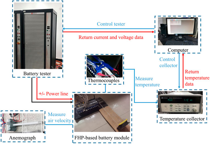
FIGURE 4. Schematic representation of the experimental system devices.
A comparison of the simulating results with the experimental data for the battery cell surface temperature distributions at the end of discharge is presented in Figure 5A. In this experiment, the battery module discharges at 1.5 C rate from 90% SOC to 10% SOC. From the results, the experimental data and calculated results are close to each other with a deviation of less than 3°C. The relative error between the simulation and the experimental results is less than 6.8%. The cell temperature deviation in the middle of the module is around 1.5°C. One of the reasons is that in the experiment, as the battery temperature rises, the ambient temperature near the battery becomes higher (around 23°C at the end of discharging), resulting in a relatively worse heat dissipation effect, so the temperature rise is higher than the simulating results. The cell temperature deviation near both sides of the module is relatively large and generally exceeds 2°C. This is because an acrylic cover is added around the module during the experiment to separate the batteries from the cooling air. It further worsens the heat dissipation effect on both sides of the module, which causes the battery temperature deviation on both sides higher on the contrary. Moreover, the temperature development of the battery cell in the middle of the module is shown in Figure 5B. The temperature difference between test results and simulation results remains below 2°C during the operating time. This is because the natural convection heat transfer coefficient is dependent on the surface temperature of the system in the experiment, which is assumed to be constant in simulation. According to the above results and comparisons, the battery-FHP-coupled model proposed in this paper is reasonable for the study of the battery thermal performance.
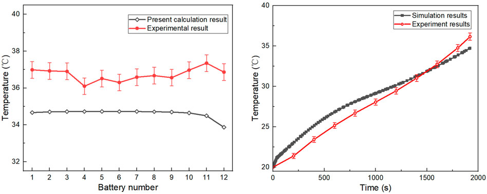
FIGURE 5. (A) Temperature distribution of 12 battery cells at the end of discharge. (B) Temperature development of the battery cell in the middle of module in discharging process.
4 Results and Discussion
4.1 Thermal Performance of the BTMS at Different Discharge Rates
We first analyze the thermal performance of the battery-FHP system at different discharge rates. The structural parameters of the FHP are shown in Table 3 above. It is noted that some of the boundary conditions used in the following simulation are different from those in Section 3. The initial SOC of the battery module is set to be 0.95, and the discharge process stops when the SOC of any battery cell drops to 0.1. The initial temperature of BTMS is set to be 10°C. The coolant air is applied to the cooling fins with the velocity of 10 m/s at the condensation section. Forced convection with a 32.4 W m−2·K−1 heat transfer coefficient is applied on the first and last battery module in the BTMS to highlight the effect of FHP; otherwise, the temperature difference is not obvious when the system is insulated. Figure 6 presents the maximum temperature development of the battery module with FHP cooling and compares it to natural convection condition. For natural convection condition, the ambient temperature is 10°C and the heat transfer coefficient on the battery module surface is 5 W m−2·K−1. It is evident that the implement of FHP can observably reduce the maximum temperature of the battery module. For instance, the maximum temperature of the battery module can be controlled under 40°C with FHP cooling under 2C discharge conditions, which is 14.41°C lower than natural convection. In addition, the higher the discharge rate, the greater the temperature difference. The maximum temperature can be decreased by 7.67°C under 0.5C discharge rate and 14.41°C under 2C discharge rate. Figure 7 shows the temperature distribution of the battery module at the end of 2C discharge rate. The battery cell closed to the cooling fins has the lowest temperature, while the batteries in the middle of the module tend to be higher. Each of the battery cells can be regarded as an evaporator for FHP; the one closed to the cooling fins has the lowest thermal resistance from the evaporator to the condenser, which causes the lowest temperature.
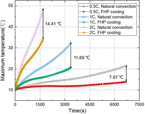
FIGURE 6. Temperature development of the BTMS at different discharge rates.
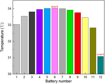
FIGURE 7. Temperature variation of the battery cells at the end of 2C discharge.
4.2 Influence of FHP Structural Parameters on Battery Thermal Performance
4.2.1 Effect of Wick Dimensionless Thickness
In this study, we consider the total FHP thickness (ttotal) constant, and the shell thickness (ts) remains unchanged (20% of ttotal). The influence of wick thickness (tw) and vapor thickness (tv) on the thermal performance of batteries is further discussed. In this paper, the dimensionless thickness of the capillary wick (τw) is defined as the ratio of tw to the sum of tw and tv in Eq. 13:
A larger dimensionless thickness represents a larger proportion of the wick thickness, which can improve the heat transfer capacity. However, it is necessary to pay attention whether the thickness of vapor core is lower than the critical value. Oppositely, a smaller dimensionless thickness causes the reduction of the heat transfer performance. The value of wick dimensionless thickness should be reasonably selected in the FHP design to meet a better heat transfer effect on battery thermal performance.
Figure 8 reveals the influence of wick dimensionless thickness on battery maximum temperature difference (△Tmax) under 2C discharge rate. In general, the temperature difference rises with the increase of τw. When the total thickness of the FHP is greater than 2 mm, as τw increases, the change of △Tmax is not obvious initially; but after it reaches a certain critical value (around 0.7), △Tmax increases significantly. When the total thickness of the FHP is 1 mm, △Tmax always maintains a relatively high value, but when τw is greater than 0.7, △Tmax tends to decrease sharply.
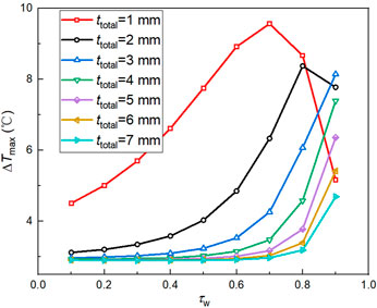
FIGURE 8. Influence of τw on battery maximum temperature difference.
The causes of the phenomenon are due to the thermal resistance distribution of the FHP. We further analyze the influence mechanism under 2C discharge rate at the ttotal value of 5 mm. Figure 9 shows the effective thermal resistance and battery temperature distribution at the end of the discharge process under different dimensionless thicknesses. When τw is small, the difference of effective thermal resistance at each battery cell is not obvious. The temperature of the battery module is mainly affected by the convection heat transfer on both sides, which shows a high temperature in the middle and low on the sides. The thickness of the vapor channel decreases as τw rises. The vapor channel thickness below critical value leads to a sharp increase of vapor flow thermal resistance, and the thermal resistance distribution of each battery cell is significantly different. The closer the battery to the cooling fins is, the lower the effective thermal resistance is. Therefore, the temperature of the battery cell close to the condensation section is lower, while the battery cell far away from the cooling fins has a relatively higher temperature. The proportion of different thermal resistances is further calculated. Figure 10A shows the variation of the thermal resistance in each heat transfer unit under different dimensionless thickness. It can be seen that the wick thermal resistance (Rw) at the evaporation section is significantly higher than the others when τw is small, and Rw increases with the increasing of τw on this occasion. When τw is more than 0.9, the thickness of the vapor channel is lower than the critical value, and the thermal resistance of the vapor channel (Rv) becomes higher and dominates the total thermal resistance. Figure 10B shows that Rw is dominant when τw is lower than 0.7, while the proportion of Rv is gradually close to Rw when τw is greater than 0.7. The nonuniform distribution of the effective thermal resistance caused by the obvious enhancement of the vapor channel thermal resistance at high wick dimensionless thickness is the main reason for the increase in the maximum temperature difference of the battery module. Therefore, the critical wick dimensionless thickness should be taken into consideration during the design process of the FHP for BTMS.
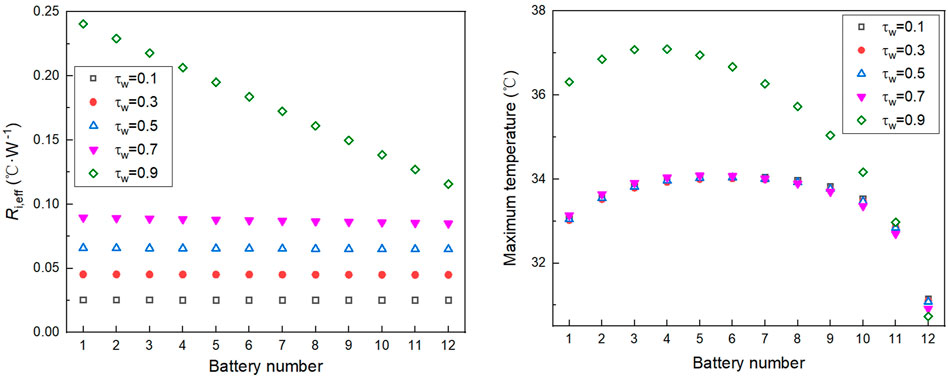
FIGURE 9. (A) Effective thermal resistance at different τw. (B) Battery cell temperature at different τw.
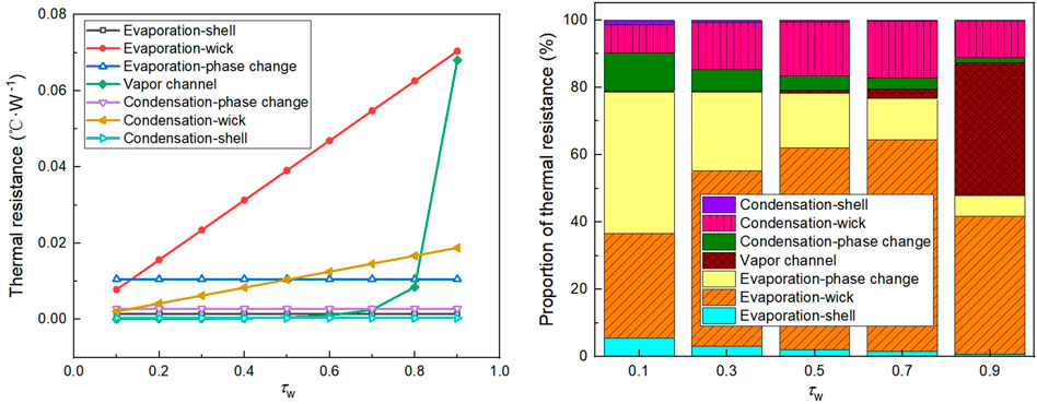
FIGURE 10. (A) Thermal resistance of each unit at different τw. (B) Proportion of different thermal resistances at different τw.
4.2.2 Effect of Wick Porosity and Particle Diameter
As mentioned above, the porosity (εw) and particle diameter (dw) of the capillary wick directly affect the effective thermal conductivity, which further influences the efficiency and heat transfer capability of the FHP. The effect of εw and dw on the maximum temperature (Tmax) and maximum temperature difference (△Tmax) of the battery module is shown in Figure 11. The coupling effect between εw and dw causes nonlinear changes on the battery thermal performance. According to Figure 11A, at a given εw smaller than 0.6, the variation of dw has a negligible effect on Tmax and △Tmax. As εw reaches to 0.7, an increase in dw from 20 to 100 μm leads to a decrease in Tmax from 37.7°C to 34.5°C. In addition, under the same value of dw, the greater εw is, the higher Tmax is. From Figure 11B, under the same value of dw, the greater εw is, the smaller ΔTmax is. ΔTmax drops significantly from 2.91°C to 2.67°C with the decrease of dw from 100 to 20 μm when the value of εw is increased to 0.7. However, the change of ΔTmax does not exceed 0.1°C when εw is greater than 0.2 and less than 0.6.
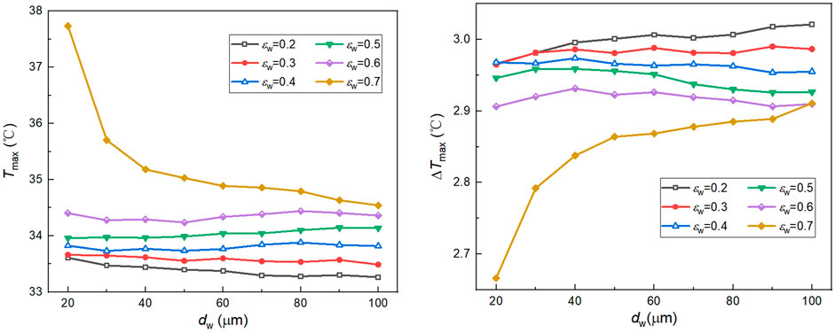
FIGURE 11. (A) Influence of εw and dw on battery maximum temperature. (B) Influence of εw and dw on battery maximum temperature difference.
The battery module should have a lower temperature and smaller temperature difference under operating conditions. It can be seen from the above that there exists a certain contradiction in the influence of wick porosity and particle diameter on the maximum temperature and the maximum temperature difference. In fact, the porosity and particle diameter of the wick together influence the thermal resistance of the wick in each heat transfer unit, which in turn impacts the thermal performance of the battery module. Figure 12 shows the influence of the wick effective thermal conductivity (λw) on the battery thermal characteristics. With the increase of λw, Tmax gradually decreases and ΔTmax increases. When λw exceeds 15 W m−1·K−1, the changing tendency of Tmax and ΔTmax turns stable. The effect of effective thermal conductivity on Tmax and ΔTmax is opposite. Therefore, during the FHP design process, an optimal effective thermal conductivity of the capillary wick should be obtained through the reasonable matching of wick porosity and particle diameter, so as to meet the requirements of the battery maximum temperature and temperature difference simultaneously.
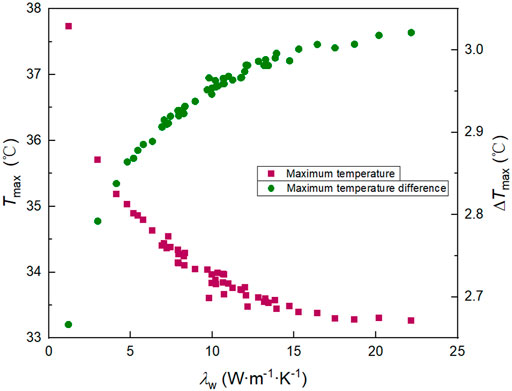
FIGURE 12. Influence of λw on battery maximum temperature and battery maximum temperature difference.
4.2.3 Effect on Heat Transfer Limitation
The structural parameters of the FHP affect not only the thermal performance of the battery pack but also the FHP heat transfer limitation. In order to prevent the FHP from drying out during the battery operating conditions, the FHP must work within the envelope range formed by different kinds of limitation parameters, such as entrainment limit, capillary limit, and boiling limit. For the battery operating temperature range, the heat transfer capability of the FHP is mainly restricted by the capillary limit and boiling limit. The capillary and boiling limits of the FHP are calculated from Eq. 14 and Eq. (15) (Reay et al., 2014):
where △Pca,max is the maximum capillary pressure difference, and μl, ρl, and σl, respectively, denote the dynamic viscosity, density, and surface tension coefficient of the liquid working medium. K is the permeability, and ρv is the density of the vapor. λv is the vapor thermal conductivity and rv is the core radius of the vapor. The heat transfer capability of the FHP depends on the minimum value of each heat transfer limit at the corresponding working temperatures. Therefore, the heat transfer limitation of the FHP (Qlim) can be expressed as:
Figure 13 shows the influence of wick dimensionless thickness on the capillary limit and boiling limit of the FHP. According to the results, when ttotal is 2 mm, the heat transfer capacity of FHP is mainly affected by the capillary limit, and it has an extreme value as τw changes. When τw is around 0.6, the capillary limit of FHP reaches the maximum. As τw increases, there is an intersection between the capillary limit and the boiling limit. The τw corresponding to this intersection is the optimal value of wick dimensionless thickness. It is worth noting that the greater the ttotal is, the smaller the optimal τw is, which is presented in Figure 14. The smaller the τw, the higher the heat transfer limitation. For the FHP in this paper with a total thickness of 5 mm, when the value of τw is close to 0.52, the heat transfer limitation of the FHP reaches an optimal value.
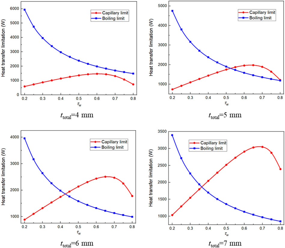
FIGURE 13. Influence of τw on FHP heat transfer limitation.
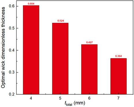
FIGURE 14. Optimal dimensionless thicknesses under different values of ttotal
Based on Eq. 14 and Eq. 15, the influence mechanism of wick porosity and particle diameter on the heat transfer limitation of FHP is shown in Figure 15. In this case, the total thickness of FHP is 5 mm. The thickness of capillary wick and vapor channel are both 1.5 mm. According to the results, Qlim increases significantly with the increase of εw. Under the same value of εw, the greater dw is, the higher Qlim is. In general, a greater wick porosity and a larger wick particle diameter can help to improve the heat transfer limitation of the FHP.
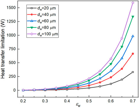
FIGURE 15. Influence of εw and dw on FHP heat transfer limitation.
4.3 Improving Battery Thermal Performance by Optimizing Structural Parameters of FHP
The previous analysis shows that the structural parameters of the FHP have influences on its heat transfer capacity and the thermal performance characteristics of the batteries. Generally, matching the maximum heat dissipation of the batteries is the precondition for the FHP design. It is necessary to further reduce the maximum temperature and maximum temperature difference of the battery pack. In situations with a complex relationship between input and output parameters, neural networks are acknowledged to produce accurate estimation because they map in a nonlinear fashion. In this study, we use a neural network model (NNM) to establish the relationship between the FHP parameters and battery thermal performance for optimizing the BTMS structure. There are three parameters to be optimized including wick dimensionless thickness (τw), porosity (εw), and particle diameter (dw). The thermal characteristics of the BTMS system in Figure 1 are taken as the optimization object. The maximum battery temperature difference (ΔTmax) is set as the objective function, which is expressed as:
In the FHP design process, it is necessary to ensure that the heat transfer limitation of the FHP is greater than the maximum heat generation of the battery module under its operating conditions at first. The discharging rate of the battery module is set as 2C from 0.95 SOC to 0.1 SOC. The ambient temperature is 10°C and the velocity of cooling air at FHP condensation section is 10 m s−1. The battery heat generation rate reaches the highest at the end of discharging, which is about 35 W for a single battery cell and 420 W for the battery module. The design margin of battery heat transfer is selected as 50%. Meanwhile, the maximum temperature of the battery module is limited below 40°C. Therefore, the constraint conditions for the optimization of the FHP can be expressed as:
We further establish the nonlinear mapping relationship between the FHP structural parameters and the objective function by the NNM. In this paper, the Back Propagation (BP) learning algorithm is adopted, which can effectively reduce the node error of the hidden layers (Suresh Kumar et al., 2020). The basic BP neural network model mainly consists of three layers including the input layer, hidden layer, and output layer as shown in Figure 16. Each layer contains a number of interconnected neurons with linked weights and activation functions. For the specified mappings among design variables and objective functions, the linked weights should be adjusted and changed as a result of learning according to the training samples after the network structure of the BP model is determined. This will finally obtain the input and output mapping relationship. The whole training process of the BP neutral network model is carried out in MATLAB software. Based on the established battery-FHP BTMS simulation platform, the thermal performance of the batteries corresponding to different FHP wick design parameters is calculated under the working conditions in Section 4.1. The database of the relationship between the FHP wick structural parameters and the maximum temperature difference of the battery module is created as the input in training process. The input layer of the neural network contains three parameters including τw, εw, and dw. The parameter in the output layer is ΔTmax, and 10 neuron nodes are set in the hidden layer. The Levenberg-Marquardt and Bayesian-regularization algorithms are used for the cross validation, including 70% training set, 15% validation set, and 15% test set. The regression model is trained for about 116 epochs after initialization through the above neural network configuration. The residual error of the model reaches to 10−5, and the convergence speed reaches the ideal level. Figure 17 shows the training results of the neural network model. The accuracy reaches above 99.97% for training, validation, and test samples, and the overall fitting accuracy of the model achieves to 99.969%. The model error conforms to the Gaussian distribution, which proves the representativeness of the training data.
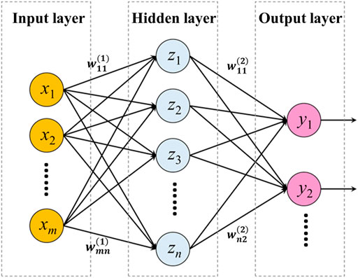
FIGURE 16. Schematic diagram of the basic BP neural network model.
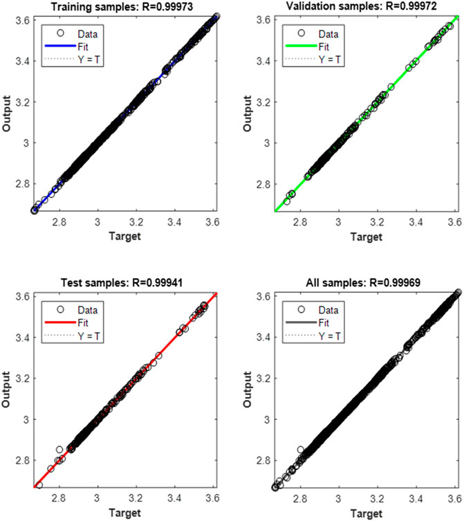
FIGURE 17. Training results of the neural network model.
According to the results, the total objective function (ΔTmax) is further optimized to obtain its minimum value. The results show that when the wick dimensionless thickness is 0.63, the wick porosity is 0.71, and the particle diameter is 26 μm, the battery module has the smallest ΔTmax, which is 2.74°C. Compared with the ΔTmax (2.96°C) of the original case in Section 4.1, the maximum temperature difference is reduced by 7.4%, which is validated by the model and shown in Figure 18. Meanwhile, the maximum temperature of the module is controlled below 40°C. The optimized FHP has achieved good results in reducing the battery temperature difference.
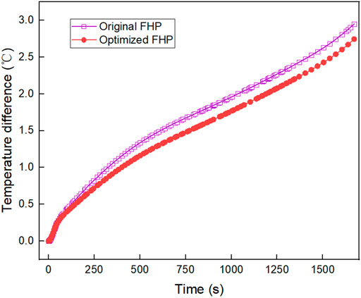
FIGURE 18. Comparison on ΔTmax between the original FHP and the optimized FHP.
5 Conclusion
In summary, we develop a flat heat pipe-based battery thermal management system for a battery module consisting of twelve prismatic battery cells. The multi-heat source thermal resistance network-based FHP model is adopted on the batteries to analyze the battery thermal performance. We further investigate the influence of FHP structural parameters on heat transfer performance of BTMS and make an optimization on the FHP. According to the analysis above, the main conclusions are achieved and listed below:
(1) The implement of FHP can reduce the battery maximum temperature below 40°C under 2C discharge rate with the cooling air velocity of 10 m/s and the ambient temperature of 10°C. The battery cell closest to the condensation section of FHP has the lowest temperature.
(2) There is a critical value of the wick dimensionless thickness (around 0.7) on affecting the battery thermal performance. The maximum temperature difference of the battery module increases significantly when exceeding this critical value. In addition, the boiling limit and the capillary limit of the FHP have an intersection point as the wick dimensionless thickness varies.
(3) The particle diameter of the wick has a negligible influence on the thermal performance of the battery module at a given porosity smaller than 0.6. When the porosity exceeds 0.7, an increase in particle diameter leads to a decrease in maximum temperature and an increase in maximum temperature difference. Larger wick porosity and particle diameter can help to improve the heat transfer limitation of the FHP.
(4) Under the same discharge condition and ambient condition, the optimized FHP with the battery module can reduce the battery maximum temperature difference from 2.96°C to 2.74°C, which is a 7.4% improvement. The optimized system can also control the battery maximum temperature below 40°C.
Data Availability Statement
The raw data supporting the conclusions of this article will be made available by the authors, without undue reservation.
Author Contributions
YW, DD, and WL jointly established the thermal resistance network model. YW and WL designed and performed the experiments. YX and HG provided the experimental equipment and assisted the experiments. YW and DD analyzed the experimental and simulation data. YW wrote the manuscript. YX and YZ provided overall guidance, supervision, and scientific knowledge support for the research.
Funding
This study was financially supported by the National Natural Science Foundation of China (No. U1864212) and State Key Laboratory of Automotive Safety and Energy (No. ZZ 2019–051).
Conflict of Interest
The authors declare that the research was conducted in the absence of any commercial or financial relationships that could be construed as a potential conflict of interest.
Publisher’s Note
All claims expressed in this article are solely those of the authors and do not necessarily represent those of their affiliated organizations, or those of the publisher, the editors and the reviewers. Any product that may be evaluated in this article, or claim that may be made by its manufacturer, is not guaranteed or endorsed by the publisher.
References
Abada, S., Marlair, G., Lecocq, A., Petit, M., Sauvant-Moynot, V., and Huet, F. (2016). Safety Focused Modeling of Lithium-Ion Batteries: A Review. J. Power Sourc. 306, 178–192. doi:10.1016/j.jpowsour.2015.11.100
Aswin Karthik, C., Kalita, P., Cui, X., and Peng, X. (2020). Thermal Management for Prevention of Failures of Lithium Ion Battery Packs in Electric Vehicles: A Review and Critical Future Aspects. Energy Storage 2 (3), 137. doi:10.1002/est2.137
Behi, H., Behi, M., Karimi, D., Jaguemont, J., Ghanbarpour, M., Behnia, M., et al. (2021). Heat Pipe Air-Cooled thermal Management System for Lithium-Ion Batteries: High Power Applications. Appl. Therm. Eng. 183, 11624. doi:10.1016/j.applthermaleng.2020.11624
Behi, H., Karimi, D., Behi, M., Jaguemont, J., Ghanbarpour, M., Behnia, M., et al. (2020). Thermal Management Analysis Using Heat Pipe in the High Current Discharging of Lithium-Ion Battery in Electric Vehicles. J. Energ. Storage 32, 101893. doi:10.1016/j.est.2020.101893
Behi, H., Karimi, D., Jaguemont, J., Gandoman, F. H., Kalogiannis, T., Berecibar, M., et al. (2021). Novel thermal Management Methods to Improve the Performance of the Li-Ion Batteries in High Discharge Current Applications. Energy 224, 120165. doi:10.1016/j.energy.2021.120165
Cen, J., and Jiang, F. (2020). Li-ion Power Battery Temperature Control by a Battery thermal Management and Vehicle Cabin Air Conditioning Integrated System. Energ. Sust. Develop. 57, 141–148. doi:10.1016/j.esd.2020.06.004
Chen, K., Hou, J., Song, M., Wang, S., Wu, W., and Zhang, Y. (2021). Design of Battery thermal Management System Based on Phase Change Material and Heat Pipe. Appl. Therm. Eng. 188, 116665. doi:10.1016/j.applthermaleng.2021.116665
Chen, K., Wu, W., Yuan, F., Chen, L., and Wang, S. (2019). Cooling Efficiency Improvement of Air-Cooled Battery thermal Management System through Designing the Flow Pattern. Energy 167, 781–790. doi:10.1016/j.energy.2018.11.011
Dai, H., Jiang, B., Hu, X., Lin, X., Wei, X., and Pecht, M. (2021). Advanced Battery Management Strategies for a Sustainable Energy Future: Multilayer Design Concepts and Research Trends. Renew. Sust. Energ. Rev. 138, 110480. doi:10.1016/j.rser.2020.110480
Dan, D., Yao, C., Zhang, Y., Qian, Y., and Zhuge, W. (2019). Research Progress and Future Prospects of Battery thermal Management System Based on Heat Pipe Technology. Chin. Sci. Bull. 64 (7), 682–693. doi:10.1360/n972018-00948
Dan, D., Yao, C., Zhang, Y., Zhang, H., Zeng, Z., and Xu, X. (2019). Dynamic thermal Behavior of Micro Heat Pipe Array-Air Cooling Battery thermal Management System Based on thermal Network Model. Appl. Therm. Eng. 162, 114183. doi:10.1016/j.applthermaleng.2019.114183
Deng, Y., Zhao, Y., Wang, W., Quan, Z., Wang, L., and Yu, D. (2013). Experimental Investigation of Performance for the Novel Flat Plate Solar Collector with Micro-channel Heat Pipe Array (MHPA-FPC). Appl. Therm. Eng. 54 (2), 440–449. doi:10.1016/j.applthermaleng.2013.02.001
Feng, X., He, X., Ouyang, M., Lu, L., Wu, P., Kulp, C., et al. (2015). Thermal Runaway Propagation Model for Designing a Safer Battery Pack with 25 Ah LiNi Co Mn O2 Large Format Lithium Ion Battery. Appl. Energ. 154, 74–91. doi:10.1016/j.apenergy.2015.04.118
Gan, Y., Wang, J., Liang, J., Huang, Z., and Hu, M. (2020). Development of thermal Equivalent Circuit Model of Heat Pipe-Based thermal Management System for a Battery Module with Cylindrical Cells. Appl. Therm. Eng. 164, 114523. doi:10.1016/j.applthermaleng.2019.114523
Greco, A., Cao, D., Jiang, X., and Yang, H. (2014). A Theoretical and Computational Study of Lithium-Ion Battery thermal Management for Electric Vehicles Using Heat Pipes. J. Power Sourc. 257, 344–355. doi:10.1016/j.jpowsour.2014.02.004
He, L., Tang, X., Luo, Q., Liao, Y., Luo, X., Liu, J., et al. (2022). Structure Optimization of a Heat Pipe-Cooling Battery thermal Management System Based on Fuzzy Grey Relational Analysis. Int. J. Heat Mass Transfer 182, 121924. doi:10.1016/j.ijheatmasstransfer.2021.121924
Hong, S., Zhang, X., Chen, K., and Wang, S. (2018). Design of Flow Configuration for Parallel Air-Cooled Battery thermal Management System with Secondary Vent. Int. J. Heat Mass Transfer 116, 1204–1212. doi:10.1016/j.ijheatmasstransfer.2017.09.092
Inui, Y., Kobayashi, Y., Watanabe, Y., Watase, Y., and Kitamura, Y. (2007). Simulation of Temperature Distribution in Cylindrical and Prismatic Lithium Ion Secondary Batteries. Energ. Convers. Manage. 48 (7), 2103–2109. doi:10.1016/j.enconman.2006.12.012
Jouhara, H., Serey, N., Khordehgah, N., Bennett, R., Almahmoud, S., and Lester, S. P. (2020). Investigation, Development and Experimental Analyses of a Heat Pipe Based Battery thermal Management System. Int. J. Thermofluids 1-2, 100004–100012. doi:10.1016/j.ijft.2019.100004
Kim, J., Oh, J., and Lee, H. (2019). Review on Battery thermal Management System for Electric Vehicles. Appl. Therm. Eng. 149, 192–212. doi:10.1016/j.applthermaleng.2018.12.020
Li, W., Xie, Y., Zhang, Y., Lee, K., Liu, J., Mou, L., et al. (2020). A Dynamic Electro‐thermal Coupled Model for Temperature Prediction of a Prismatic Battery Considering Multiple Variables. Int. J. Energ. Res 45 (3), 4239–4264. doi:10.1002/er.6087
Liang, J., Gan, Y., and Li, Y. (2018). Investigation on the thermal Performance of a Battery thermal Management System Using Heat Pipe under Different Ambient Temperatures. Energ. Convers. Manage. 155, 1–9. doi:10.1016/j.enconman.2017.10.063
Liang, J., Gan, Y., Li, Y., Tan, M., and Wang, J. (2019). Thermal and Electrochemical Performance of a Serially Connected Battery Module Using a Heat Pipe-Based thermal Management System under Different Coolant Temperatures. Energy 189, 116233. doi:10.1016/j.energy.2019.116233
Lin, C., Xu, S., Chang, G., and Liu, J. (2015). Experiment and Simulation of a LiFePO4 Battery Pack with a Passive thermal Management System Using Composite Phase Change Material and Graphite Sheets. J. Power Sourc. 275, 742–749. doi:10.1016/j.jpowsour.2014.11.068
Liu, F., Lan, F., and Chen, J. (2016). Dynamic thermal Characteristics of Heat Pipe via Segmented thermal Resistance Model for Electric Vehicle Battery Cooling. J. Power Sourc. 321, 57–70. doi:10.1016/j.jpowsour.2016.04.108
Mahamud, R., and Park, C. (2011). Reciprocating Air Flow for Li-Ion Battery thermal Management to Improve Temperature Uniformity. J. Power Sourc. 196 (13), 5685–5696. doi:10.1016/j.jpowsour.2011.02.076
Onda, K., Ohshima, T., Nakayama, M., Fukuda, K., and Araki, T. (2006). Thermal Behavior of Small Lithium-Ion Battery during Rapid Charge and Discharge Cycles. J. Power Sourc. 158 (1), 535–542. doi:10.1016/j.jpowsour.2005.08.049
Panchal, S., Dincer, I., Agelin-Chaab, M., Fraser, R., and Fowler, M. (2016). Thermal Modeling and Validation of Temperature Distributions in a Prismatic Lithium-Ion Battery at Different Discharge Rates and Varying Boundary Conditions. Appl. Therm. Eng. 96, 190–199. doi:10.1016/j.applthermaleng.2015.11.019
Park, S., and Jung, D. (2013). Battery Cell Arrangement and Heat Transfer Fluid Effects on the Parasitic Power Consumption and the Cell Temperature Distribution in a Hybrid Electric Vehicle. J. Power Sourc. 227, 191–198. doi:10.1016/j.jpowsour.2012.11.039
Poplaski, L. M., Faghri, A., and Bergman, T. L. (2016). Analysis of Internal and External thermal Resistances of Heat Pipes Including Fins Using a Three-Dimensional Numerical Simulation. Int. J. Heat Mass Transfer 102, 455–469. doi:10.1016/j.ijheatmasstransfer.2016.05.116
Qian, Y., Guo, S., Zeng, Z., Zhang, Y., Zhuge, W., Dan, D., et al. (2020). Prediction of Effective thermal Conductivity of a Porous Capillary Wick in a Vapor Chamber. Sci. Sin.-Tech. 51 (1), 55–64. doi:10.1360/sst-2019-0412
Rao, Z., and Wang, S. (2011). A Review of Power Battery thermal Energy Management. Renew. Sust. Energ. Rev. 15 (9), 4554–4571. doi:10.1016/j.rser.2011.07.096
Rao, Z., Wang, S., Wu, M., Lin, Z., and Li, F. (2013). Experimental Investigation on thermal Management of Electric Vehicle Battery with Heat Pipe. Energ. Convers. Manage. 65, 92–97. doi:10.1016/j.enconman.2012.08.014
Reay, D. A., Kew, P. A., and McGlen, R. J. (2014). “Heat Transfer and Fluid Flow Theory,” in Heat Pipes (Oxford: Butterworth-Heinemann), 15–64. doi:10.1016/b978-0-08-098266-3.00002-9
Sheikholeslami, M., and Ganji, D. D. (2016). Heat Transfer Improvement in a Double Pipe Heat Exchanger by Means of Perforated Turbulators. Energ. Convers. Manage. 127, 112–123. doi:10.1016/j.enconman.2016.08.090
Shi, G., Chen, S., Yuan, H., You, H., Wang, X., Dai, H., et al. (2021). Determination of Optimal Indicators Based on Statistical Analysis for the State of Health Estimation of a Lithium-Ion Battery. Front. Energ. Res. 9, 1–16. doi:10.3389/fenrg.2021.690266
Suresh Kumar, P., Behera, H. S., K, A. K., Nayak, J., and Naik, B. (2020). Advancement from Neural Networks to Deep Learning in Software Effort Estimation: Perspective of Two Decades. Comput. Sci. Rev. 38, 100288. doi:10.1016/j.cosrev.2020.100288
Thomas, K. E., and Newman, J. (2003). Thermal Modeling of Porous Insertion Electrodes. J. Electrochem. Soc. 150 (2), A176. doi:10.1149/1.1531194
Tran, T.-H., Harmand, S., Desmet, B., and Filangi, S. (2014). Experimental Investigation on the Feasibility of Heat Pipe Cooling for HEV/EV Lithium-Ion Battery. Appl. Therm. Eng. 63 (2), 551–558. doi:10.1016/j.applthermaleng.2013.11.048
Wang, J., Gan, Y., Liang, J., Tan, M., and Li, Y. (2019). Sensitivity Analysis of Factors Influencing a Heat Pipe-Based thermal Management System for a Battery Module with Cylindrical Cells. Appl. Therm. Eng. 151, 475–485. doi:10.1016/j.applthermaleng.2019.02.036
Wang, Q., Jiang, B., Xue, Q. F., Sun, H. L., Li, B., Zou, H. M., et al. (2015). Experimental Investigation on EV Battery Cooling and Heating by Heat Pipes. Appl. Therm. Eng. 88, 54–60. doi:10.1016/j.applthermaleng.2014.09.083
Xu, X. M., and He, R. (2014). Review on the Heat Dissipation Performance of Battery Pack with Different Structures and Operation Conditions. Renew. Sust. Energ. Rev. 29, 301–315. doi:10.1016/j.rser.2013.08.057
Xu, X., Tang, W., Fu, J., Li, R., and Sun, X. (2019). Plate Flat Heat Pipe and Liquid-Cooled Coupled Multistage Heat Dissipation System of Li-Ion Battery. Int. J. Energ. Res 43 (3), 1133–1141. doi:10.1002/er.4341
Yang, N., Zhang, X., Li, G., and Hua, D. (2015). Assessment of the Forced Air-Cooling Performance for Cylindrical Lithium-Ion Battery Packs: A Comparative Analysis between Aligned and Staggered Cell Arrangements. Appl. Therm. Eng. 80, 55–65. doi:10.1016/j.applthermaleng.2015.01.049
Yao, M., Gan, Y., Liang, J., Dong, D., Ma, L., Liu, J., et al. (2021). Performance Simulation of a Heat Pipe and Refrigerant-Based Lithium-Ion Battery thermal Management System Coupled with Electric Vehicle Air-Conditioning. Appl. Therm. Eng. 191, 116878. doi:10.1016/j.applthermaleng.2021.116878
Ye, Y., Saw, L. H., Shi, Y., and Tay, A. A. O. (2015). Numerical Analyses on Optimizing a Heat Pipe thermal Management System for Lithium-Ion Batteries during Fast Charging. Appl. Therm. Eng. 86, 281–291. doi:10.1016/j.applthermaleng.2015.04.066
Zhang, C., Jiang, Y., Jiang, J., Cheng, G., Diao, W., and Zhang, W. (2017). Study on Battery Pack Consistency Evolutions and Equilibrium Diagnosis for Serial- Connected Lithium-Ion Batteries. Appl. Energ. 207, 510–519. doi:10.1016/j.apenergy.2017.05.176
Zhang, Z., and Wei, K. (2020). Experimental and Numerical Study of a Passive thermal Management System Using Flat Heat Pipes for Lithium-Ion Batteries. Appl. Therm. Eng. 166, 114660. doi:10.1016/j.applthermaleng.2019.114660
Glossary
Variables
A area [m2]
C capacity [J·kg−1·K−1]
d diameter [μm]
h height [m]
hfg latent heat [J·kg−1]
H heat transfer coefficient [W·m−2·K−1]
I current [A]
K permeability [m2]
l length [m]
n number [-]
p pressure [Pa]
Pr Prandtl number [-]
q heat generation rate per unit volume [W·m−3]
Q heat rate [W]
r radius [m]
R thermal resistance [°C·W−1]
Rgas gas constant [J·kg−1·K−1]
Re Reynolds number [-]
s spacing [mm]
t thickness [m]
T temperature [°C]
△T temperature difference [°C]
U voltage [V]
w width [m]
Subscripts
b boiling
c condensation
ca capillary
e evaporation
eff effective
f cooling fluid
l liquid
lim limitation
max maximum
min minimum
o ohmic
p polarization
pc phase change
s shell
v vapor
w wick
x in x direction
y in y direction
z in z direction
Greek Symbols
ε porosity [-]
λ thermal conductivity [W·m−1·K−1]
μ dynamic viscosity [Pa·s]
ρ density [kg·m−3]
σ accommodation coefficient [-]
σl surface tension coefficient of liquid [N·m−1]
τ dimensionless thickness [-]
Abbreviations
BP back propagation
BTMS battery thermal management system
FHP flat heat pipe
NCM nickel cobalt manganese
NNM neural network model
OCV open circuit voltage
PCM phase change material
SOC state of charge.
Keywords: lithium-ion battery, battery thermal management system, flat heat pipe, battery thermal performance, structure optimization
Citation: Wang Y, Dan D, Xie Y, Li W, Guo H and Zhang Y (2022) Study on the Influence of Flat Heat Pipe Structural Parameters in Battery Thermal Management System. Front. Energy Res. 9:797664. doi: 10.3389/fenrg.2021.797664
Received: 19 October 2021; Accepted: 22 December 2021;
Published: 28 January 2022.
Edited by:
Qingsong Wang, University of Science and Technology of China, ChinaReviewed by:
Fei Gao, China Electric Power Research Institute (CEPRI), ChinaYunhua Gan, South China University of Technology, China
Copyright © 2022 Wang, Dan, Xie, Li, Guo and Zhang. This is an open-access article distributed under the terms of the Creative Commons Attribution License (CC BY). The use, distribution or reproduction in other forums is permitted, provided the original author(s) and the copyright owner(s) are credited and that the original publication in this journal is cited, in accordance with accepted academic practice. No use, distribution or reproduction is permitted which does not comply with these terms.
*Correspondence: Yi Xie, Y2xhdWRleGllQGNxdS5lZHUuY24=; Yangjun Zhang, eWp6aGFuZ0B0c2luZ2h1YS5lZHUuY24=