 Mohamed H. Mohamed
 Faris Alqurashi
 Dominique Thévenin4
- 1Mechanical Power Engineering Department, Faculty of Engineering EL-Mattaria, Helwan University, Cairo, Egypt
- 2Mechanical Engineering Department, College of Engineering and Islamic Architecture, Umm Al-Qura University, Makkah, Saudi Arabia
- 3Mechanical Engineering Department, College of Engineering, University of Bisha, Bisha, Saudi Arabia
- 4Laboratory of Fluid Dynamics and Technical Flows, University of Magdeburg “Otto von Guericke”, Magdeburg, Germany
In this study, the performance of a new wind turbine design derived from a conventional Savonius turbine is optimized by numerical simulation. The new design consists of three blades without passage between them (closed center). The coupling between the CFD codes (ANSYS Fluent) and the optimizer (OPAL) is used through an automatic procedure in-house codes, as documented, for example, in Thévenin et al.’s Optimization and Computational Fluid Dynamics (2008). A single-objective function (output power coefficient, Cp) is considered as the target of the optimization technique and the shape of the blade as an optimization parameter and relies on evolutionary algorithms. An optimal solution can emerge from this optimization study. By comparison between regular design (semi-cylindrical shape blades) and the optimal configuration, a considerable improvement (up to 7.13% at λ = 0.7) of the optimal configuration performance can be obtained in this manner.
1 Introduction
Due to the deep energy crisis in the world, research studies and development activities in the field of renewable energy, especially wind energy, have considerably increased during the last few years in many countries. Although wind energy technology has been greatly improved during that time, the available technical design is not enough to extract wind energy and convert it into mechanical energy for residential and remote areas which have low wind speed. Savonius turbines (Figure 1) and derived configurations could be a very good solution for such conditions. This is the purpose of the present study.
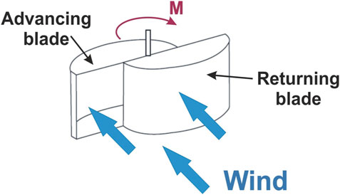
FIGURE 1. Conventional Savonius rotor (Gupta et al., 2008).
2 Purpose of the Present Study
Many literature reports have appeared in the last 2 decades related to Savonius turbines and their performance. The theoretical and experimental results concerning the performance of Savonius turbines in these previous publications have indicated that such turbines are interesting for some specific applications but show very low efficiency. It is thus essential to increase the performance of these turbines. Therefore, several design improvements have been introduced to enhance the efficiency of the Savonius rotor (Huda et al., 1992; Menet and Nachida, 2004; Saha and Rajkumar, 2006; Irabu and Roy, 2007; Menet, 2007; Hassan et al., 2021; Mohamed et al., 2021). For instance, Kedare et al. (2009) studied the helical design of Savonius turbines to improve the performance, and they found that the helical shape enhanced the self-starting of the turbine. In 2006, Saha and Rajkumar investigated the twisted design of Savonius turbines, and they improved the performance, but it is a costly and complex design (Saha and Rajkumar, 2006). Installing a guide box around the rotor was studied by Irabu and Roy (2007), which improved the performance of the three blade rotor, but it was a very complex design. Iio et al. (2011) increased the performance by installing a shielding plate. Elbatran et al. (2017) found that installing a ducted nozzle increases the performance to obtain a maximum power coefficient equal to 0.25. Kerikous and Thévenin (2019) optimized the blade thickness to improve the performance, and they found that the relative increase was 12%. Dual splitters were added by Patel and Patel (2021) to the Savonius turbine blades to improve the aerodynamic distribution of the flow inside the blades, and they succeeded in increasing the performance by 7.3%. Ramadan et al. (2021) used S-shaped blades with deflectors to enhance the performance. They enhanced the performance, and the maximum power coefficient was 0.24. The self-starting of the three blade rotor is studied by Salleh et al. (2021) by installing frontal guiding plates. In 2021, Mohamed et al. (2021) optimized the position of the frontal guiding plates and its effect on the Savonius turbine performance, and they concluded that the guiding plates increased the maximum power coefficient to be 0.31.
In the present study, we will numerically optimize the blade shape of a Savonius turbine using one new concept: it is a turbine consisting of three semi-cylindrical blades without a passage in between, as shown in Figure 2. This concept has been proposed in several publications. In this study, the geometry is always treated in two dimensions since there is no geometrical change along the third (vertical) direction.
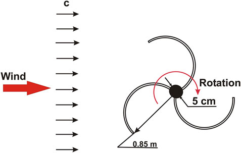
FIGURE 2. Schematic shape of the modified design.
3 Mathematical Optimization
In the field of turbomachinery, the automatic optimization is a relatively new field, but in the last decade, some research and several publications used the mathematical optimization in the turbomachine field to improve the performance. [For more details, see Van den Braembussche et al. (2008).] Optimization is utilized to distinguish the blade shape that best satisfies some specified requirements pertaining here to the efficiency of a new design. Optimization criteria can be taken into consideration both for mechanical and aerodynamic features, as used in the current article. The main objective when designing any system is enhancing the turbine design to obtain higher efficiency and higher power output. In addition, it should be taken into consideration that turbomachinery normally works outside the design point condition and in the off-design performance. Therefore, the current calculations consider a typical maximum output power coefficient which occurs at the speed ratio λ = 0.7.
The optimization method attempts to calculate the n design variables Xi (i = 1 … n) that minimize or maximize the user-defined objective functions, denoted as OF(U(Xi), Xi), where U(Xi) is the computational fluid dynamic solution of the aerodynamic relations (Thévenin and Janiga, 2008). In the recent study, the free design parameters taken into consideration for the optimization are first the blade shape which consists of two parameters (X1 and Y1), as shown in Figure 3. For the most complex case involving a concurrent optimization, one performance goal is taken into consideration as objective function which is the simulation output that must be maximized to extreme possible values: the Savonius turbine power output coefficients.
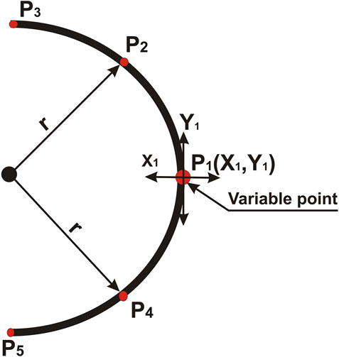
FIGURE 3. Schematic shape of the optimization parameters.
4 Optimization Methodology
In the last decades, the category “optimization” has been severally utilized in the engineering work to introduce a trial-and-error, manual sequence at the variance of the real, automatic optimizing methods. So, this is recently modifying quickly. Thus, in the current article, the optimum blade shape will depend on automatic optimization as an initial step toward deep intensive optimization of the two considerable factors affects the performance of a modified Savonius rotor. Real-valued functions f(x) of an N component vector arguments x = (x1, x2, … , xN) whose values are restricted to satisfy several real-valued equations hk (x) = 0, some of inequalities gj (x) ≥ 0, and variable bounds
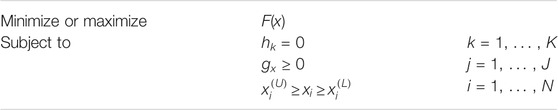
The general problems are called the constrained optimization problems. The problem in which there is no constraints are unconstrained optimization problems.

and

A suitable algorithm must be selected in the optimization work. A deep experience is obtainable in our research group concerning the mathematical optimization depending on computational fluid dynamic studies (Thévenin and Janiga, 2008). Our own optimization library is employed in this study, called OPtimization ALgorithms (OPAL), containing several optimization methodologies. OPAL had already been used with different computational fluid dynamic solvers (in-house codes, CFX, and ANSYS Fluent), and it was utilized successfully to enhance a variety of implementations, such as heat exchangers (Hilbert et al., 2006), turbomachines (Mohamed et al., 2008a; Mohamed et al., 2008b; Mohamed et al., 2010; Mohamed et al., 2011), or burners (Thévenin et al., 2005; Janiga and Thévenin, 2007).
For the present configuration, evolutionary algorithms are used. The used parameters are listed as follows: twenty population sizes are used in the optimization sequence; eleven generations are utilized with 50% survival probability and 33.3 average probability. In addition, crossover probability is 16.7, and 100% mutation probability is used with mutation magnitude 30%. The reader should note that mutation magnitude is multiplied by 0.8 at every generation. For instance, the mutation magnitude will be 4% (±2%) after 10 generations. For solution stability, mutation magnitude should be decreased throughout the optimization sequence.
OPAL is the optimizer which is used in this study as a decision maker for the tested configurations; it is coupled with geometry and a mesh generator called Gambit. After the mesh quality checking in Gambit, a computational fluid dynamic code (ANSYS Fluent) is used to solve the aerodynamic flow around the turbine for every configuration sent by the optimizer. For every configuration, the objective function (power coefficients) is calculated and stored in the result file. All steps of the optimization sequence is conducted in an automatic manner utilizing journal scripts (Gambit and Fluent), and the main controller of the right sequence is the C program which is called the master program. After every generation, the optimizer takes a decision with the new generation with new input parameters after studying the stored results from the old generation. This sequence of mathematical optimization and coupling with CFD codes is very complex, and some previous studies described the procedure in detail, for example, Thévenin et al. (2005), Hilbert et al. (2006), Janiga and Thévenin (2007), Thévenin and Janiga (2008).
5 Flow Simulation Methodology
From the previous studies, it is noted that an accurate computation fluid dynamic simulation of the aerodynamic flow around the Savonius rotors is a complex and challenging mission, fundamentally, due to the rotor’s deeply time-dependent nature. Additionally, a strong separation around the blades plays a significant role for turbine efficiency and the power output. Therefore, the quality of the numerical simulations and the procedure should be checked with great care. Then the methodology sequence must be validated and verified.
All aerodynamic flow simulations (denoted also computational fluid dynamics, CFD) introduced in the current article depend on the industrial software ANSYS Fluent. The Semi-Implicit Method for Pressure-linked Equations (SIMPLE) algorithm is utilized to calculate the unsteady Reynolds-averaged Navier–Stokes equation for pressure–velocity coupling. Discretization of the aerodynamic flow parameters and the turbulent values utilized the finite-volume formulation with the second-order upwind scheme. The realizable k − ɛ model is used in this study as a turbulence model to calculate the flow characteristics inside the domain. The realizable k − ɛ model is recommended for rotating bodies.
The realizable k-ϵ model usually provides improved results for swirling flows and flows involving separation when compared to the standard k-ϵ model.
• Transport equations:
where
where S is the modulus of the mean rate of the strain tensor.
In these equations, Pk represents the generation of turbulence kinetic energy due to the mean velocity gradients, calculated as follows:
Pb is the generation of the turbulence kinetic energy due to buoyancy, negligible for our applications:
where Prt is the turbulent Prandtl number for energy and gi is the component of the gravitational vector in the ith direction. The default value of Prt is 0.85.
The coefficient of thermal expansion, β, is defined as follows:
• Modeling turbulent viscosity
While Cμ is constant in the standard k-ϵ model, in the realizable k-ϵ model, this coefficient is calculated as follows:
and
where
where
• Model constants
During the simulation of the current design, the two-dimensional simulation is suitable (no geometry change in the third direction when the turbine has an end plate); therefore, the extremely fine and accurate grid can be utilized. Therefore, the sliding mesh model (SMM) is used in the current study, and four complete revolutions are always computed with fixed time-step equivalents to the half of one degree of the azimuth angle. The first revolution is used to initiate the correct flow solutions. The remaining three revolutions are used to calculate the turbine performance (in particular the power coefficient Cp and the torque coefficient Cm) by averaging the results of these three revolutions. By checking the results, it should be noted that the results are constant noticeably by further iteration with time. Every revolution takes around 360 min on the normal PC of computing time. To complete the CFD setting accurately, the mesh independence study has been executed to eliminate the effect of the mesh from the results. This study indicated that 175,000 control volumes are appropriate to obtain accurate results of the simulation.
6 Results and Discussions
6.1 Validation of the Computational Procedure
Before investigating design modifications, the whole numerical model was validated by comparing the current model results with previous published experimental data (Hayashi et al., 2005) for a conventional Savonius rotor. After this comparison, the current model results shown in Figure 4 demonstrated excellent agreement obtained between the present model results and published experiment results for these conventional configurations, at least for λ > 0.3. It is clear from Figure 4 that both the torque and the power output coefficients are extremely well predicted. As a consequence, it is now possible to start the investigation of modifications of the Savonius turbine.
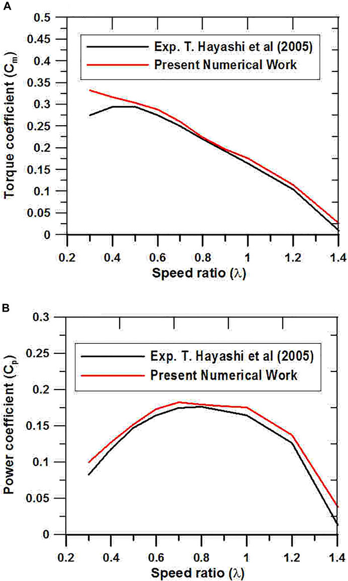
FIGURE 4. Validation of the current CFD model. (A) Torque coefficient (top), (B) power coefficient (bottom), with comparison to published experiment result (Hayashi et al., 2005).
Recently, a modified rotor design of a three-bladed turbine was introduced by many studies to enhance the performance of the standard system. Beyond the geometry difference from the conventional turbine, one issue must be specifically investigated in this study: by changing the blade shape from semi-cylindrical, the performance of the Savonius turbine can be enhanced. Therefore, we should ask a question now: is it possible to enhance the efficiency by changing the shape of the blades (different from the semi-cylindrical shape)?
6.2 Blade Shape Optimization
In this study, the comparison between the conventional (semi-cylindrical blades) and optimal design is considered. It is not sure that such blade shapes lead to an optimal performance. Therefore, an optimization of this geometry based on splines between five points (see Figure 3) has been investigated.
The optimum shape of the blade is obtained by applying the previously discussed mathematical optimization procedure (evolutionary algorithms relying on automated evaluations through CFD). The optimization and all the simulations are executed for the speed ratio λ = 0.7, taking into consideration an upstream wind velocity U = 10 m/s. However, this value of the tip speed ratio (λ) is fixed in all simulations. The reader should note that from the previous publications, λ = 0.7 matches the maximum output power coefficient of the standard Savonius turbine.
Two free parameters (X1 and Y1) are studied in this shape optimization as two degrees of freedom for the optimizer (OPAL). The two parameters control the position of the center point of the blades, as shown in Figure 3. A selected domain for the optimization was defined for every parameter as space limits. These domain spaces are defined as (0.3 : 0.7) for (X1/R) and (−0.3 : 0.3) for (Y1/R).
Eventually, the optimization procedure also includes two free parameters (the degrees of freedom) simultaneously: X1 and Y1. For each new configuration, one single objective (power output coefficient) has been calculated by CFD simulations and should be maximized by the optimizing process.
The results showed in Figure 5 and Figure 6 indicated that the target objective is extremely affected by the two free parameters X1 and Y1. In addition, as a whole, 120 several geometrical settings were assessed by computational fluid dynamics.

FIGURE 5. Two–degree of freedom parameters of the optimization procedure and the power coefficient.
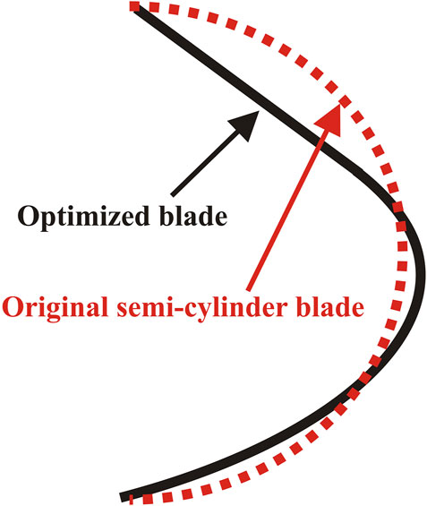
FIGURE 6. Optimal configuration compared to the original turbine (semi-cylindrical shape).
An optimum design can thus easily be distinguished for λ = 0.7. Therefore, this optimal design corresponds to the point coordinates X1/R = 0.621 3 and Y1/R = − 0.062 23, as presented in Figure 7. Furthermore, this optimum configuration leads to a power coefficient Cp = 0.163 5 and a torque coefficient Cm = 0.234.
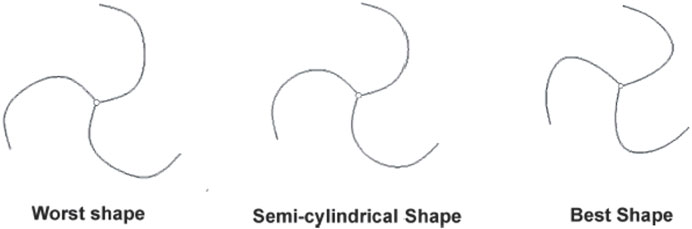
FIGURE 7. Optimal and worst configurations compared to the modified turbine (semi-cylindrical shape).
With deep comparison between the optimum configuration (optimization output) and the conventional design (semi-cylindrical blade shape), the optimum configuration found by the optimizing process corresponds simultaneously to an increase in the power coefficient by 0.014 55 and in the torque coefficient by 0.020 8 at λ = 0.7. Furthermore, for the power coefficient, this gain leads to a relative increase in the performance by 7.13% compared to the modified turbine. The off-design performance is now checked to trust the gain through the full operating range of the tip speed ratios λ. Therefore, the turbine power coefficient of this design has been evaluated for several useful λ-values through the operating of the Savonius turbine, as represented in Figure 8. The modified turbine results are also presented for comparing the results. Furthermore, Figure 8 indicates the improvement of the power output coefficient noted throughout for middle values of λ (e.g., between λ = 0.7 to λ = 1.1), in comparison to the modified turbine. In Figures 9, 10, the velocity and pressure distributions of the flow around the optimized configuration as well as the original turbine are presented at several azimuth angles. It is clear that there are deep differences between the two turbines in the distributions due to different shapes. The low-pressure zones behind the optimized blades are larger than the zones of the original blades. These low-pressure zones enhanced the flow inside the blade and increased the impact of the flow on the turbine.
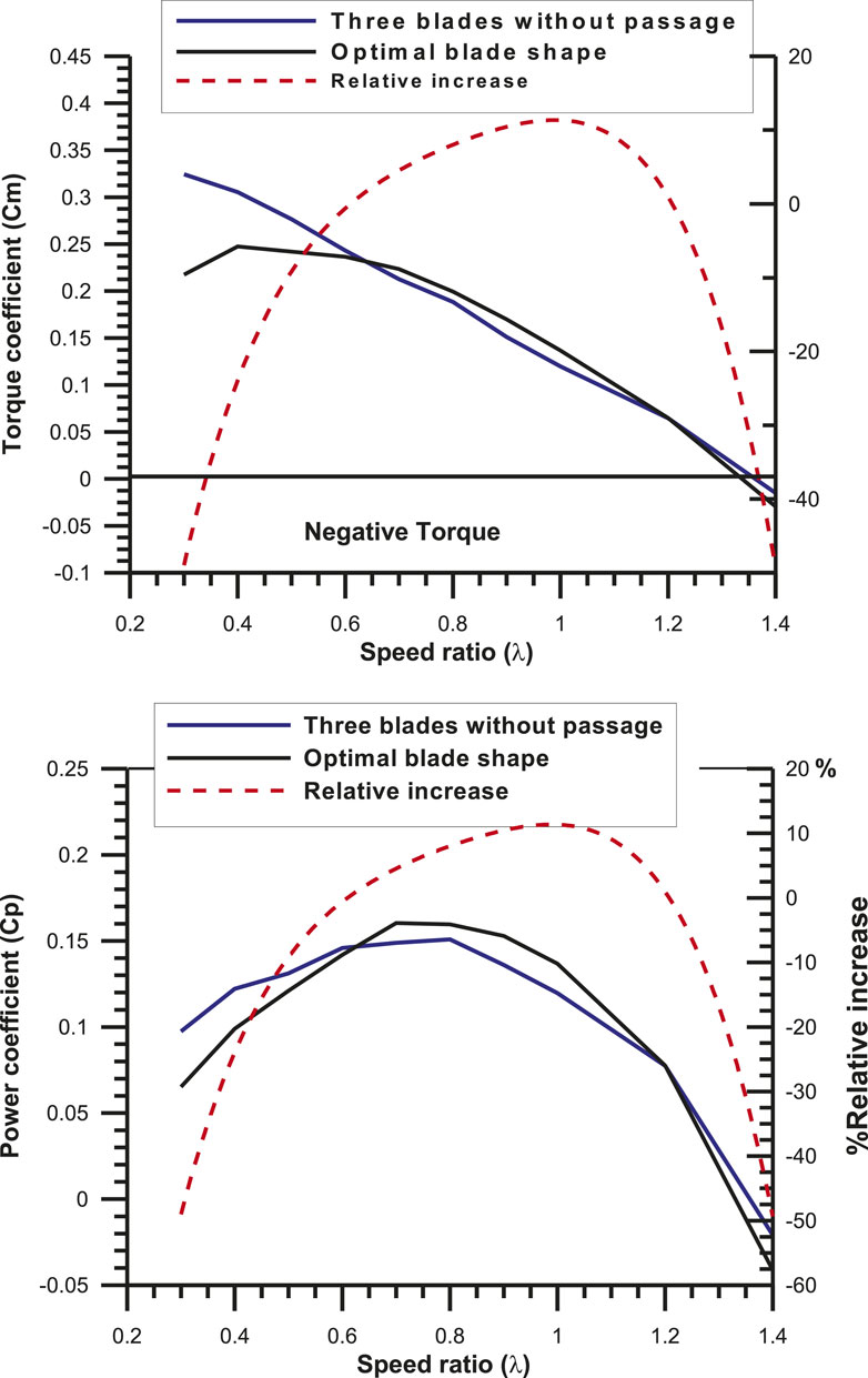
FIGURE 8. Power coefficient of the optimized configuration compared to the modified turbine.
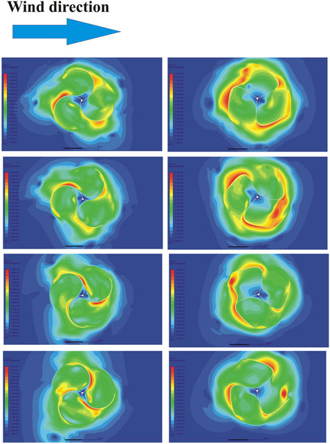
FIGURE 9. Velocity contours of the optimized configuration compared to the original turbine.
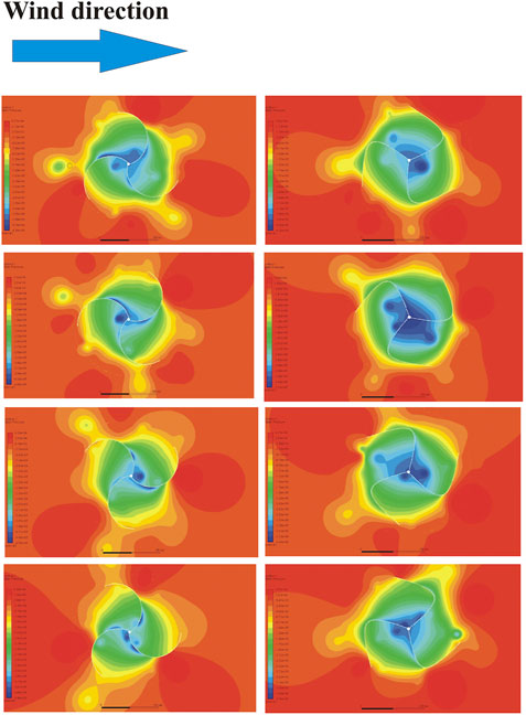
FIGURE 10. Pressure contours of the optimized configuration compared to the original turbine.
7 Conclusion
This study numerically optimizes the blade shape of the design based on the conventional Savonius turbine but involving three blades without a passage in between. The automatic optimization is used in this study to modify the three-blade Savonius turbine to improve the turbine performance. In the optimization study, the optimizer used evolutionary algorithms, and all geometrical designs were assessed using a mathematical procedure by computational fluid dynamics. The optimization sequence can be identified as a considerably better configuration than the regular turbine (semi-cylindrical shape), leading, in particular, to a relative raise (gain) of efficiency by 7.13% at the tip speed ratio equal to 0.7. This increase in the performance is also noted for the torque coefficient, and it has even higher values for middle tip speed ratios λ. Therefore, performance of the blades with a new shape is extremely positive at middle values of the speed ratio.
Data Availability Statement
The raw data supporting the conclusion of this article will be made available by the authors, without undue reservation.
Author Contributions
MM contributed to methodology, validation, software, and writing—original draft preparation. FA helped with conceptualization, methodology, and writing—original draft preparation. DT assisted with supervision, conceptualization, data curation, and writing—reviewing and editing.
Conflict of Interest
The authors declare that the research was conducted in the absence of any commercial or financial relationships that could be construed as a potential conflict of interest.
Publisher’s Note
All claims expressed in this article are solely those of the authors and do not necessarily represent those of their affiliated organizations, or those of the publisher, the editors, and the reviewers. Any product that may be evaluated in this article, or claim that may be made by its manufacturer, is not guaranteed or endorsed by the publisher.
Acknowledgments
The project is supported financially by a bursary of the University of Bisha, Saudi Arabia.
References
Elbatran, A. H., Shehata, A. S., and Ahmed, Y. M. (2017). Performance Study of Ducted Nozzle Savonius Water Turbine, Comparison with Conventional Savonius Turbine. Energy 134, 566584. doi:10.1016/j.energy.2017.06.041
Gupta, R., Biswas, A., and Sharma, K. K. (2008). Comparative Study of a Three-Bucket Savonius Rotor with a Combined Three-Bucket Savonius-Three-Bladed Darrieus Rotor. Renew. Energ. 33 (9), 1974–1981. doi:10.1016/j.renene.2007.12.008
Hassan, Z., Elsayed, K., Shabana, Y. M., and Mohamed, M. H. (2021). Comprehensive Influence of the Additional Inner Blades with Different Configurations on the Performance of a Savonius Wind Turbine. Energy Sourc. A: Recovery, Utilization, Environ. Effects 43, 1–19. doi:10.1080/15567036.2021.1956645
Hayashi, T., Li, Y., and Hara, Y. (2005). Wind Tunnel Tests on a Different Phase Three-Stage Savonius Rotor. JSME International Journal. Ser. B, Fluids Thermal Engineering 48 (1), 9–16. doi:10.1299/jsmeb.48.9
Hilbert, R., Janiga, G., Baron, R., and Thévenin, D. (2006). Multi-objective Shape Optimization of a Heat Exchanger Using Parallel Genetic Algorithms. Int. J. Heat Mass Transfer 49, 2567–2577. doi:10.1016/j.ijheatmasstransfer.2005.12.015
Huda, M. D., Selim, M. A., Islam, A. K. M. S., and Islam, M. Q. (1992). Performance of an S-Shaped Savonius Rotor with a Deflecting Plate. RERIC Int. Energ. J. 14 (1), 25–32.
Iio, S., Katayama, Y., Uchiyama, F., Sato, E., and Ikeda, T. (2011). Influence of Setting Condition on Characteristics of Savonius Hydraulic Turbine with a Shield Plate. J. Therm. Sci. 20 (3), 224228. doi:10.1007/s11630-011-0462-9
Irabu, K., and Roy, J. N. (2007). Characteristics of Wind Power on Savonius Rotor Using a Guide-Box Tunnel. Exp. Therm. Fluid Sci. 32 (2), 580–586. doi:10.1016/j.expthermflusci.2007.06.008
Janiga, G., and Thévenin, D. (2007). Reducing the CO Emissions in a Laminar Burner Using Different Numerical Optimization Methods. Proc. Inst. Mech. Eng. A: J. Power Energ. 221 (5), 647–655. doi:10.1243/09576509jpe387
Kedare, S. B., Kamoji, M. A., and Prabhu, S. V. (2009). Performance Tests on Helical Savonius Rotors. Energy 34 (3), 521529. doi:10.1016/j.renene.2008.06.002
Kerikous, E., and Thévenin, D. (2019). Optimal Shape of Thick Blades for a Hydraulic Savonius Turbine. Renew. Energ. 134, 629638. doi:10.1016/j.renene.2018.11.037
Menet, J., and Nachida, B. (2004). “Increase in the Savonius Rotors Efficiency via a Parametric Investigation,” in European Wind Energy Conference EWEA - Poster Presentations, Aerodynamics and Aeroacoustics, Spain.
Menet, J.-L. (2007). “Aerodynamic Behaviour of a New Type of Slow-Running VAWT,” in Wind Energy Proceedings of the Euromech Colloquium (Berlin, Heidelberg: Springer), 235–240. Book chapter. doi:10.1007/978-3-540-33866-6_43
Mohamed, M. H., Janiga, G., and Thévenin, D. (2008). “Performance Optimization of a Modified Wells Turbine Using Non-symmetric Airfoil Blades,” in ASME Turbo Expo Conference, (GT2008-50815), Berlin, Germany. doi:10.1115/gt2008-50815
Mohamed, M. H., Janiga, G., Pap, E., and Thévenin, D. (2008). “Optimal Performance of a Savonius Turbine Using an Obstacle Shielding the Returning Blade,” in Ninth International Congress of Fluid Dynamics and Propulsion ASME-ICFDP9, (ICFDP9-EG-249), Alexandria, Egypt.
Mohamed, M. H., Janiga, G., Pap, E., and Thévenin, D. (2010). Optimization of Savonius Turbines Using an Obstacle Shielding the Returning Blade. Renew. Energ. 35 (11), 2618–2626. doi:10.1016/j.renene.2010.04.007
Mohamed, M. H., Janiga, G., Pap, E., and Thévenin, D. (2011). Optimal Blade Shape of a Modified Savonius Turbine Using an Obstacle Shielding the Returning Blade. Energ. Convers. Manage. 52 (1), 236–242. doi:10.1016/j.enconman.2010.06.070
Mohamed, M. H., Alqurashi, F., and Thévenin, D. (2021). Performance Enhancement of a Savonius Turbine under Effect of Frontal Guiding Plates. Energ. Rep. 7, 6069–6076. doi:10.1016/j.egyr.2021.09.021
Patel, V., and Patel, R. (2021). Free Energy-Extraction Using Savonius Hydrokinetic Rotor with Dual Splitters. Mater. Today 45 (6), 53545361. doi:10.1016/j.matpr.2021.01.928
Ramadan, A., Hemida, M., Abdel-Fadeel, W. A., Aissa, W. A., and Mohamed, M. H. (2021). Comprehensive Experimental and Numerical Assessment of a Drag Turbine for River Hydrokinetic Energy Conversion. ocean Eng. 227 (1), 108587. doi:10.1016/j.oceaneng.2021.108587
Saha, U. K., and Rajkumar, M. J. (2006). On the Performance Analysis of Savonius Rotor with Twisted Blades. Renew. Energ. 31 (11), 1776–1788. doi:10.1016/j.renene.2005.08.030
Salleh, M. B., Kamaruddin, N. M., Mohamed-Kassim, Z., and Bakar, E. A. (2021). Experimental Investigation on the Characterization of Self-Starting Capability of a 3-bladed Savonius Hydrokinetic Turbine Using Deflector Plates. ocean Eng. 228, 108950. doi:10.1016/j.oceaneng.2021.108950
Thévenin, D., and Janiga, G. (2008). Optimization and Computational Fluid Dynamics. Berlin, Heidelberg: Springer-Verlag.
Thévenin, D., Zähringer, K., and Janiga, G. (2005). “Automatic Optimization of Two-Dimensional Burners,” in European Combustion Meeting, Louvain-La-Neuve, Belgium (ECM05), 240/1–240/6.
Keywords: Savonius turbine, wind energy, optimization, CFD, performance
Citation: Mohamed MH, Alqurashi F and Thévenin D (2022) Automatic Blade Shape Optimization of a Three-Bladed Modified Savonius Turbine. Front. Energy Res. 9:796860. doi: 10.3389/fenrg.2021.796860
Received: 17 October 2021; Accepted: 01 December 2021;
Published: 05 January 2022.
Edited by:
Alex Maurício Araújo, Federal University of Pernambuco, BrazilReviewed by:
Scappaticci Lorenzo, Università degli Studi Guglielmo Marconi, ItalyLiang Li, University of Strathclyde, United Kingdom
Copyright © 2022 Mohamed, Alqurashi and Thévenin. This is an open-access article distributed under the terms of the Creative Commons Attribution License (CC BY). The use, distribution or reproduction in other forums is permitted, provided the original author(s) and the copyright owner(s) are credited and that the original publication in this journal is cited, in accordance with accepted academic practice. No use, distribution or reproduction is permitted which does not comply with these terms.
*Correspondence: Mohamed H. Mohamed, bWhtb2hhbWVkQHVxdS5lZHUuc2E=