- National Key Laboratory of Science and Technology on Vessel Integrated Power System, Naval University of Engineering, Wuhan, China
With the increasingly serious crisis of fossil energy and environmental pollution, clean renewable energy becomes the inevitable choice of energy structure adjustment. The instability of output power of distributed renewable energy system greatly affects the operation of DC microgrid. The hybrid energy storage system (HESS) composed of High-Energy Battery (HEB) and High-Power Battery (HPB) can solve the above problems. Thus, this paper proposes a dynamic and cooperative control strategy for multi-HESS based on state of charge (SOC). Based on the traditional LPF method and droop control, this paper proposes a control strategy that requires no communication among multiple hybrid energy storage (HES) modules. This method can realize the stable control of HEB current, reduce the change times of HEB charging-discharging mode, prevent HEB from overcharging and overdischarging, prolong the service life of HEB and balance different energy storage SOC, so as to improve the operation stability and economy of DC microgrid. In addition, the method has certain robustness against sudden failures. Simulation and experiment results show the effectiveness of the proposed method.
Introduction
The increasing penetration rate of renewable energy such as photovoltaic and wind power promotes the development of DC microgrid (Kathiresan et al., 2020; Zhou et al., 2020). Compared with AC microgrid, DC microgrid has no problems such as synchronization, reactive power transmission, harmonic current and converter loss, so it has attracted more and more attention (Rahimi and Ghadiriyan, 2019; Song et al., 2019).
However, due to the intermittent impact of renewable energy distributed generation and the short-term impact of some large loads, the stability of DC microgrid is severely challenged. Therefore, the corresponding energy storage system should be equipped to enhance the anti-interference ability of DC microgrid (Singh and Lather, 2021). On the one hand, combining High-Energy Battery (Such as lithium battery, lead-acid battery, sodium sulfur battery) with High-Power Battery (Such as supercapacitor, flywheel energy storage, super-magnetic energy storage) to form HESS is an important way of energy storage configuration based on the existing energy storage technology and satisfying the demand for DC microgrid (Kotra and Mishra, 2019; Mathews and Rajeev, 2020). On the other hand, in order to improve the access flexibility of energy storage system, and avoid the cost increase of using large-capacity converters in centralized energy storage system and the problems of operational reliability, distributed multi-HESS should be used (Su et al., 2018).
In terms of applying HESS to suppress grid-connected power fluctuations of distributed power generation, many scholars have studied various control strategies according to the characteristics of different types of energy storage, such as LPF method (Manandhar et al., 2015), fuzzy logic control (FLC) (Musilek et al., 2017; Mathews and Rajeev, 2020), wavelet decomposition method (Chiang et al., 2017), layered drooping control (Li et al., 2016; Zhang et al., 2018), virtual inertial control (Ming et al., 2017; Wang et al., 2017), machine learning (Chen et al., 2020) and so on. The above method mainly focuses on centralized HESS, when extended to distributed multi-HESS, they have some inapplicability. With the increase of using time, the differences among HES modules become larger and larger. If not restrained and controlled, the performance of HES modules will be seriously affected.
The concept of a virtual power rating was introduced in Literature (Hoang and Lee, 2019) to achieve accurate power sharing between batteries. However, this control method requires communication, and the scope of its application has certain limitations. In literature (Zhou et al., 2018), multi-HEB SOC is divided into five regions, and the whole system is divided into six working modes. However, this method may switch modes frequently under the circumstance of high-frequency fluctuation, leading to system instability. Most importantly, the above literatures mainly focus on the cooperative control of multiple energy storage units with the same medium and the same property.
In view of the collaborative control problem of distributed multi-HESS in DC microgrid, a power control strategy for multi-HESS was proposed based on the consensus protocol in literature (Chen et al., 2019). The communication was established among different energy storage units, and the SOC of different energy storage units was balanced by the consensus protocol, thus effectively solving the problem of balanced power distribution among multi-HESS. In literature (Wu et al., 2020), the control system automatically switches the operating mode based on the DC bus voltage, the supercapacitor voltage and the accumulator state. However, these methods still depend on external communication and are not suitable for situations requiring high reliability. To solve this problem, literature (Chen et al., 2016) proposed voltage-current droop control for HEB and voltage-change rate-current droop control for HPB. When the system only relies on the local information of the energy storage, it realizes the automatic power distribution between the components of different types of energy storage. However, this method is controlled by difference, and the deviation of bus voltage is large.
In order to solve the problem of high dependence on external communication in power distribution, this paper takes the island operation of DC microgrid as the research object, based on the traditional LPF method and droop control, proposes a SOC based power secondary distribution method without communication among HES modules. The control system automatically redistributes power according to SOC of different energy storage to achieve SOC balance. The smooth control of HEB current can be realized by using the characteristic that HPB voltage cannot change suddenly, so as to reduce the number of charging-discharging mode changes of HEB and extend the service life of HEB. The effectiveness of the proposed control strategy for distributed multi-hybrid energy storage module parallel system is verified by simulation and experiment.
System Model
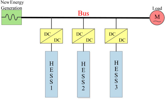
The schematic diagram of DC microgrid with multi-HESS is shown in Figure 1, which mainly includes renewable energy power generation unit, AC/DC load and energy storage unit. Each part is a distributed structure, and each unit is connected to the DC bus through the corresponding converter. The power relationship of each part is as follows:
PGen is the power generated by renewable energy, PHESS is the total power of multi-HESS, and PLoad is the total load power, including AC load and DC load.
In system analysis and calculation, the load of renewable energy power generation and power electronic equipment access can be equivalent to a controllable current source, which can be positive or negative. When it is positive, the renewable energy power generation is greater than the load; when negative, the load is greater than the renewable energy power generation.
HESS in Figure 1 consists of High-Energy Battery and High-Power Battery. High-Energy Battery has high energy density and long storage time, but low power density and low cycle times. High-Power Battery has high power density and high cycle times, but low energy density and short energy storage time.
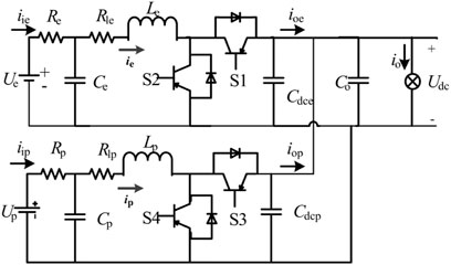
The single HES module topology adopted in this paper is shown in Figure 2. Ue and Up, Re and Rp are the voltage and resistance of High-Energy Battery and High-Power Battery respectively. Udc is the DC bus voltage. The converter in the Figure 2 is a bidirectional Buck-Boost converter. Ce and Cp, Le and Lp are respectively the filter capacitance and inductance of the converters. Rle and Rlp are the internal resistance of respective inductors. S1-S4 are power tubes. Cdce and Cdcp are filter capacitors of converters respectively. Co is the bus voltage regulator capacitor. (Subscript “e” means High-Energy Battery, and subscript “p” means High-Power Battery.)
Cooperative Control Strategy for Multi-HESS
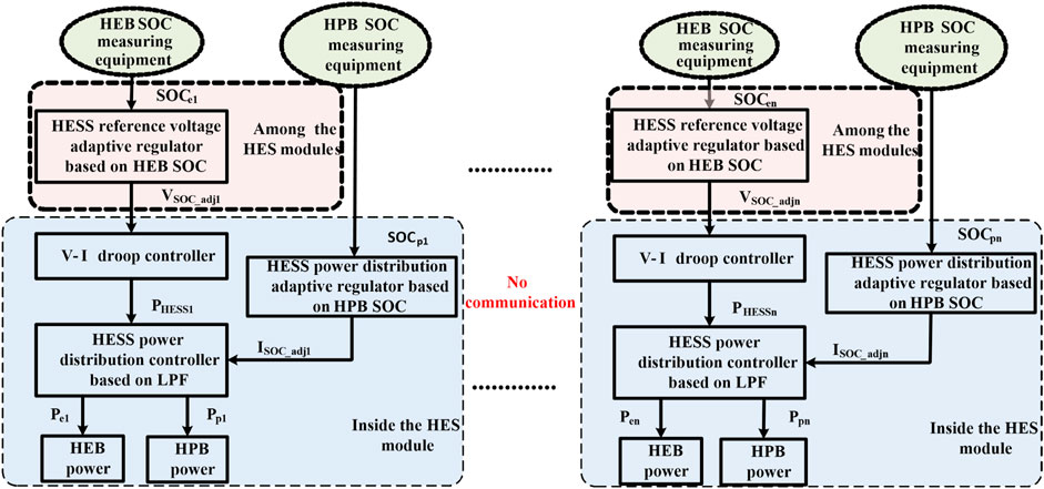
The overall architecture of multi-HESS collaborative control strategy is shown in Figure 3. The improved LPF control structure is adopted to regulate the power distribution within the single HES module. Based on the HPB SOC, the output power of HEB and HPB inside the module is adjusted to maintain the HPB SOC in a healthy range as far as possible. Among the multiple HES modules, the output of the whole module is regulated through the reference bus voltage adaptive regulator based on HEB SOC, so as to maintain the overall available capacity of each HES module relatively consistent. Since each HES module adopts V-I droop control, the coordinated control among HES modules does not require communication, which has high reliability and scalability, plug and play, and is convenient for installation and deployment.
Basic Control Structure
In microgrid, there are many control methods for converters, among which droop control is a widely used decentralized control method. It does not need communication, and only uses local information to realize the coordination control between distributed power supplies. It is suitable for DC microgrid with high reliability requirements, such as islands, reefs and ships, etc. Therefore, in order to maximize the autonomous control of each HES module, and enhance the system reliability and “plug and play” capability, the converter of HESS adopts droop control to stabilize the DC bus voltage.
V-I droop control (Li et al., 2016; Zhang et al., 2018) can be expressed as:
Uref is the value of DC bus voltage under no load, Uo∗ is the specified value of converter output voltage after correction, and RV is the droop coefficient.
The value of RV is determined by Eq. 3:
Uomin is the allowable minimum steady state value of DC bus voltage, and Iomax is the maximum current value that DC/DC converter can output/input.
Ignoring the line impedance, the output current relationship of several DC/DC converters with V-I droop control is shown as follows.
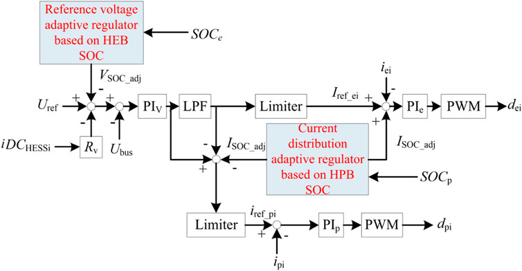
The control structure of High-Power Battery consists of a droop control outer loop and a voltage and current double closed-loop, as shown in Figure 4. Uref, Ubus and Iref_p respectively represent the reference voltage of the bus, the actual voltage of the bus and the reference current of the High-Power Battery.
HEB is mainly used to follow the current instructions given by the power distribution controller, as shown in Figure 5. Iref_e and ie respectively represent the reference current and the actual current of the High-Energy Battery.
HES Module Control Based on LPF
Figure 6 is the control structure diagram of LPF-based. Reasonable power distribution method is the key to the stability and reliability of HESS. The traditional LPF method has less computation and parameters, and the control is simple. It can realize the power distribution based on frequency without any communication. Thus, this paper adopts LPF method for power distribution. On the basis of the traditional LPF control, the adaptive power redistribution module is added to regulate the output of different energy storage units in real time and balance the remaining electric quantity. The adaptive power redistribution modules represented by the two blue squares are described in detail in the next section.
iDCHESSi is the sum of the current at the bus end of the DC/DC converter in the ith HES module, as shown in Eq. 5. iei and ipi are the current of High-Energy Battery and High-Power Battery in the ith HES module, while dei and dpi are the control signals of DC/DC converter. The limiter prevents the reference current from exceeding the converter maximum current.
iDCei and iDCpi are the current at the bus end of the DC/DC converter connected with High-Energy Battery and the High-Power Battery in the ith HES module.
Overall Idea of Adaptive SOC Layered Control
During the use of the HESS, there are different initial SOC and rated capacity of each energy storage unit connected by the converter in a certain working condition. If SOC are not considered, some energy storage units may overcharge or overdischarge, affecting the stable operation of the whole system. Therefore, the balanced control of energy storage SOC is the key to the stable and economical operation of HESS.
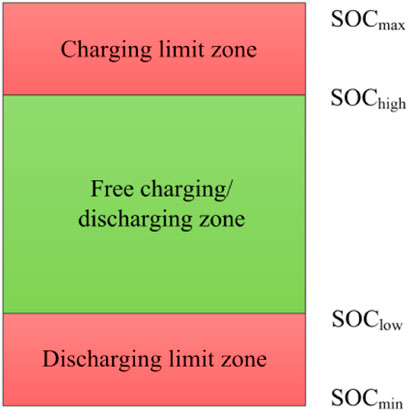
In order to prevent energy storage units from overcharging/overdischarging and frequent charging/discharging change, this paper adopts adaptive SOC layered control strategy. According to the SOC level of each energy storage unit, it is divided into different operating range as shown in Figure 7.
(1) Free charging/discharging zone. When SOClow≤SOC≤SOChigh, the energy storage unit can conduct normal charge/discharge in accordance with the droop relationship, without imposing other control operations based on SOC.
(2) Charging limit zone. When SOChigh≤SOC≤SOCmax, the energy storage charging will be limited, and as SOC gets closer and closer to SOCmax, the charging limit becomes more and more serious until no more charging is allowed.
(3) Discharging limit one. When SOCmin≤SOC≤SOClow, the energy storage discharging will be limited, and as SOC gets closer and closer to SOCmin, the discharging limit becomes more and more serious until no more discharging is allowed.
Adaptive SOC Control Method Inside the HES Module
In HESS, power fluctuation is usually divided into low frequency and high frequency, which are borne by High-Energy Battery and High-Power Battery respectively. The response speed of High-Power Battery is obviously faster than that of High-Energy Battery. DC microgrid is operating in island mode, the High-Power Battery will quickly compensate the power shortage in case of sudden change of load. When the High-Power Battery responds quickly, its SOC fluctuates. Then, the High-Energy Battery responds slowly to maintain the stability of the High-Power Battery SOC, achieving a dynamic adaptive balance. Through such a master-slave double structured with adaptive control, the system will gradually transfer the power deficiency firstly borne by the High-Power Battery to the High-Energy Battery, which can make the High-Energy Battery charge/discharge change relatively smooth, reduce the depth of the charge/discharge, prolong the life of High-Energy Battery, and avoid overcharge/overdischarge of High-Power Battery.
The ampere-hour integral method is used to calculate the SOC of High-Power Battery (Manandhar et al., 2015).
SOCp is the real-time SOC of High-Power Battery, SOCp0 is the initial SOC, T is the running time, μp is the charging/discharging efficiency, ip is the charging/discharging current, CNp is the rated capacity of the HPB.
According to the layered control principle introduced in Figure 5, partial charging/discharging current of High-Power Battery is transferred to the High-Energy Battery. This paper designs ISOC_adj that is the current of the High-Power Battery transferred to the High-Energy Battery based on the concept of partition operation as shown in Figure 7. The specific expression is shown in Eq. 7:
Iref_P refers to the initial reference current of the High-Power Battery, and Vdiff refers to the difference between the reference voltage and the actual voltage of the bus, which is used to characterize the charging and discharging state of energy storage unit at this time.
Vdiff > 0 means the energy storage unit is in charge, and Vdiff < 0 means it is in discharge.
Iref_p* and Iref_e* represent the regulated High-Power Battery and High-Energy Battery reference current.
According to Eqs 7–10, when the High-Power Battery is in the charging limit zone, a certain proportion of the charging current is transferred to the High-Energy Battery according to the current SOCp. The higher the SOCp is, the larger the proportion of the transferred current will be. On the contrary, when the High-Power Battery is in the discharging limit zone, situation is the opposite. Finally, the High-Power Battery SOC is always in a reasonable operating range.
Among the HES Modules
High-Power Battery has low energy density. The adaptive regulating frequency of power among HES modules is much lower than that in a single HES module, so the High-Energy Battery SOC can be used as an indicator of the whole HES module available capacity.
The ampere-hour integral method is used to calculate the SOC of High-Energy Battery (Manandhar et al., 2015).
SOCe is the real-time SOC of High-Energy Battery, SOCe0 is the initial SOC, T is the running time, μe is the charging/discharging efficiency, ie is the charging/discharging current, CNe is the rated capacity of the HEB.
The proposed adaptive regulation strategy of reference voltage based on SOC is used to regulate the reference voltage of droop control model.
VSOC_adj is the reference voltage regulation. In order to improve the regulation performance of the strategy and avoid system oscillation caused by re-regulation of critical SOC, the layered regulation framework shown in Figure 7 is adopted. The specific algorithm is as follows:
k is the proportional amplification gain, which is determined by the maximum power of the converter and the requirement of the system on the regulation ability.
According to Eqs 12, 13 when the SOC of an energy storage unit is in the charging limit zone, the reference voltage value of the DC/DC convert output should be increased to reduce the charging current of the energy storage unit. On the contrary, when the SOC is in the discharging limit zone, the situation is the opposite. Finally, SOC of different energy storage units tends to be relatively consistent. The specific process is shown in Figure 8, where the X-axis is the SOC of energy storage unit and the Y-axis is the regulator of the reference voltage value of the DC/DC convert output. The model is simple and easy to implement, and the switching between modes is relatively smooth.
Stability Analysis and Control Parameter Selection
Stability Analysis Model
Because the control strategy proposed in this paper presents a coupling state inside a single HES module, it is difficult to adopt impedance analysis method. Thus, this paper intends to adopt small-signal analysis method to establish a mathematical analysis model for a single HES module as a whole.
Since resistive load increases system damping, constant power load (CPL) decreases system damping. So in the worst case, assume that the load on the system contains only CPL. Once the system is stable in the worst case, it is stable in all cases. Thus, in the study, the load will select the CPL, which can be expressed as:
iLoad is load current, PCPL is load power, udc is bus voltage transient value.
The small signal model can be obtained as follows:
Udc is steady-state value of bus voltage at equilibrium point.
The state equation of the main circuit is shown in Eq. 16:
de and dp are the duty cycle instantaneous value of HEB and HPB control signal.
The small signal model can be obtained as follows:
Eq. 17 is written in matrix form:
The small-signal model of the HEB control loop in Figure 6:
Xv and Xie are the steady-state values of the input of the voltage loop and the current loop in the control loop of HEB. IDCref is the total current reference value, Iref_e is the current reference value of HEB, Tf is the filtering time constant of the low-pass filter, kvp and kvi, kep and kei are the PI parameters of the voltage loop and the current loop in the control loop of HEB.
The deformation of Eq. 21 can be obtained as follows:
The duty cycle of HEB converter can be expressed as:
The control loop of HPB can be expressed as:
Xip is the steady-state input value of the current loop in the HPB control loop, Iref_p is the current reference value of the HPB, and kpp and kpi are the PI parameters of the current loop in the HPB control loop.
In combination with Eqs 24, 27, the small-signal model can be written as:
The state vector Δx2 of the controller variable can be expressed as:
According to Eqs 12–22 and 25, 26, we can get:
The upper control input vector Δx3 can be expressed as:
The energy storage unit has an integral relation between SOC and time. Despite the existence of such an integral relationship, the present state value of the SOC is calculated and output by sampling, so the changes of the output current and voltage are difficult to reflect the changes of the SOC in very short time. Therefore, the SOC is only treated as an input signal in small signal modeling. At the same time, considering that the change of SOC is not as rapid as the change of voltage and current, delay sampling strategy is generally adopted, and LPF can be used to replace short delay.
As VSOC_adj and ISOC_adj are both piecewise functions in the optimization of upper power allocation considering SOC. In the stability analysis, only the case with the worst stability is considered, that is, they are all in the discharge limit region:
Small signal transformation is performed for Eqs 31, 32:
w is the cutoff frequency of LPF.
In summary, the following formula can be obtained by combining Eqs 19, 20 and 25:
By comprehensively considering Eqs 18, 29, 30, it can be obtained:
Stability Analysis and Control Parameter Selection
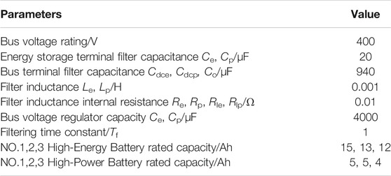
Figure 9 is the closed-loop pole distribution diagram of Eq. 35 when different PI parameters are selected (the black arrow indicates the increasing direction of the parameters taken). SOC limited boundaries of High-Energy Batteries and High-Power Batteries SOCmin, SOCmax, SOClow, SOChigh respectively are 50, 70, 56, 63, and 40, 80, 55, 65%. Other specific simulation parameters are shown in Table 1.
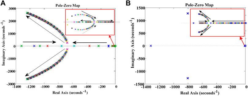
FIGURE 9. Closed-loop pole distribution of voltage outer loop PI parameters: (A) The scale parameter kvp increases from 0.1 to 20; (B) The integral parameter kvi increases from 0.1 to 50).
It can be seen from Figure 9 that when kvi and kvp change in the specified range, the system pole is always on the left of the Y-axis, so the system is always stable. As shown in Figure 9A, the poles close to the imaginary axis are conjugate poles when the voltage outer loop proportionality parameter kvp is less than 6, and it is an underdamped system. At the same time, with the increase of kvp, the damping ratio of the system gradually increases, and the overshoot decreases. Therefore, when kvp = 5, the overshoot of the system is small and the response speed is fast. As shown in Figure 9B, when kvi is greater than 30, the closed loop dominates the pole conjugate. At this time, the system has good dynamic response characteristics. As kvi continues to increase, the peak value of the system decreases, but the response time increases. Therefore, the trade-off is kvi = 35.
The same method is adopted for other control parameters and their stability analysis. The PI parameters of the proposed method are obtained and summarized as shown in Table 2.
Simulation and Experiment
In this paper, PSCAD/EMTDC software will be used for simulation. In order to fully verify the performance of the proposed HESS control strategy, three groups of HESS will be set up. HESS1 is overdischarged, HESS2 is in the free charging/discharging zone, and HESS3 is overcharged. The structure of each group is shown in Figure 2. The overall simulation model is shown in Figure 10. In this simulation, lithium battery is used for HEB and supercapacitor is used for HPB. Simulation parameters are shown in Tables 1, 2.
Step Load Change
In this case, the response of the system to consecutive step load changes is simulated to observe the net power decomposition between High-Energy Battery and High-Power Battery. The specific waveform is shown in Figure 11A. At 10 s, the load current increases from 50 to 125 A, then drops back to 50 A at 25 s, and finally jumps to 150 A at 50 s. The initial SOC of three High-Energy Batteries and High-Power Batteries are 55, 62, 67, 60, 70%. To verify the effectiveness of the proposed strategy, it will be compared with the LPF-based HESS control method without SOC regulation, that is, the control method shown in Figure 5 removes the SOC regulation module represented by the blue square. The results are shown in Figures 11B–K.
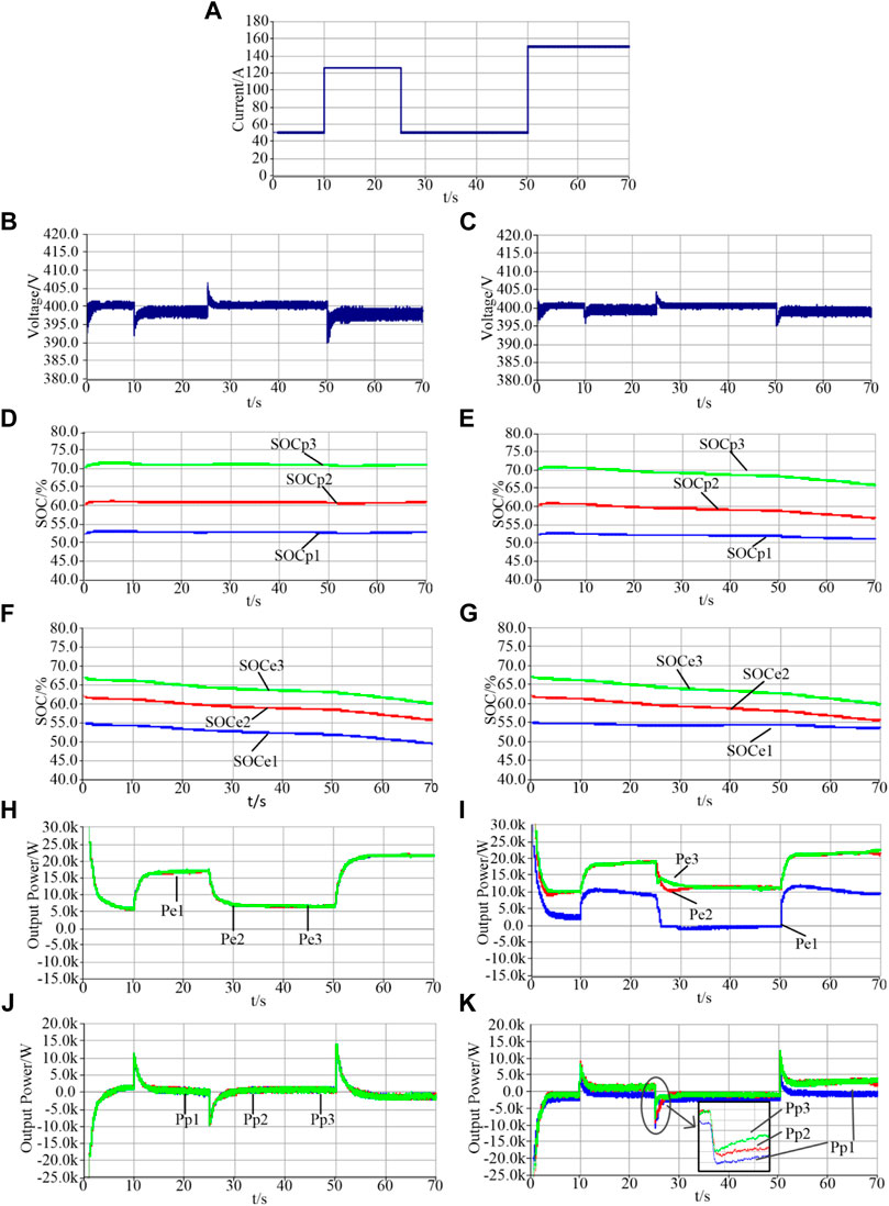
FIGURE 11. Simulation results under step load condition: (A) Load current; (B) Bus voltage-No SOC regulation; (C) Bus voltage-SOC regulation; (D) High-Power Battery SOC-No SOC regulation; (E) High-Power Battery SOC-SOC regulation; (F) High-Energy Battery SOC-No SOC regulation; (G) High-Energy Battery SOC-SOC regulation; (H) The output power of High-Energy Battery-No SOC regulation; (I) The output power of High-Energy Battery-SOC regulation; (J) The output power of High-Power Battery-No SOC regulation; (K) The output power of High-Power Battery-SOC regulation).
It can be seen from Figures 11B,C that both methods can effectively cope with the step change of load and make the deviation of bus voltage stable within 2.5%. However, the voltage deviation rate of the proposed method is reduced by about 50%.
Figures 11D–G shows that SOC of each energy storage unit cannot be balanced without SOC regulation. Considering the practical differences of energy storage units, SOC difference will become larger and larger, eventually leading to the overcharge or overdischarge of some energy storage units. However, under the SOC coordinated control method proposed in this paper, SOC can tend to be consistent which can effectively prevent some energy storage units from overcharging/overdischarging, and improve the stability and reliability of the system.
According to the comparison among Figures 11H–K, it can be seen that under the SOC regulation, the energy storage unit with SOC higher than the limit increases its output power when discharging. The energy storage unit with SOC lower than the limit decreases output power when discharging. Under this regulation, SOC of each energy storage unit will gradually tend to be consistent. At the same time, High-Power Battery quickly responds to sudden load change, then gradually falls back, and gradually transfers the power shortage to the High-Energy Battery. In other words, frequency distribution is realized in the HESS, and the output/input current of the High-Energy Battery is smoothed, which effectively extends the service life of the High-Energy Battery and improves the economy and reliability of the energy storage system.
Random Fluctuations in Renewable Energy Generation
Considering the random fluctuation of renewable energy, the response characteristics of High-Energy Battery and High-Power Battery in the control strategy proposed in this paper are studied. The initial state of each energy storage unit is consistent with the previous section. Figure 12 shows the output curve of renewable energy adopted in simulation, the power response and SOC changing of High-Energy Batteries and High-Power Batteries.
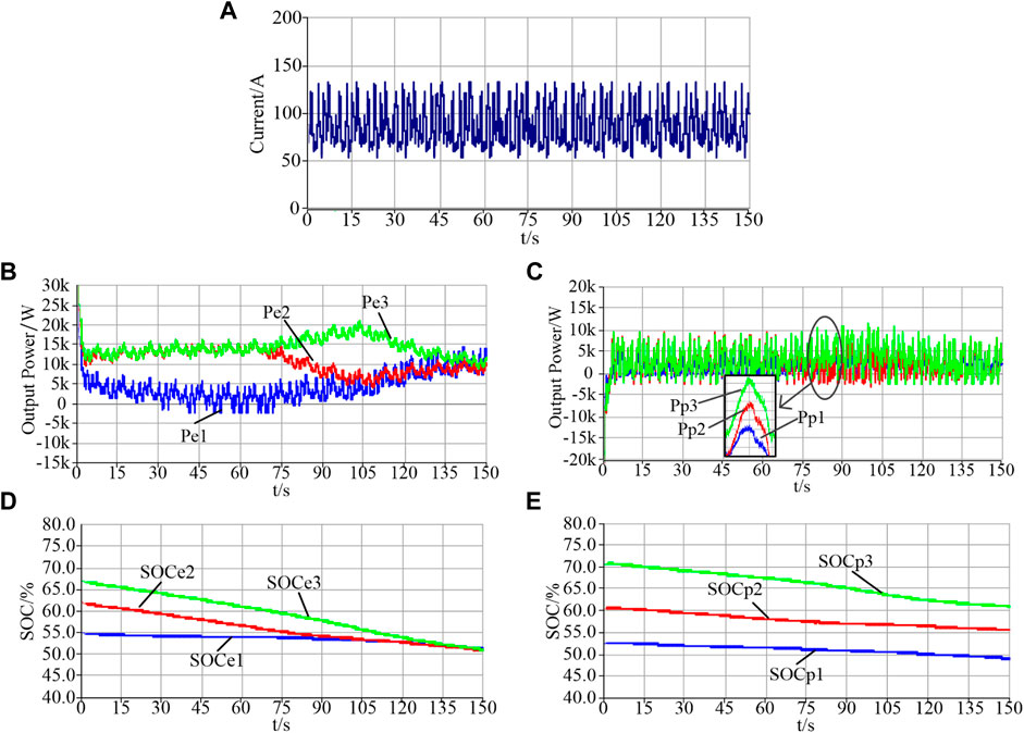
FIGURE 12. Simulation results under random load condition: (A) Random power of renewable energy-Random output of renewable energy; (B) Output power of High-Energy Battery; (C) Output power of High-Power Battery; (D) High-Energy Battery SOC; (E) High-Power Battery SOC).
From Figures 12B,C, it can be seen that multi-HESS can effectively make real-time power compensation in the case of random fluctuation of renewable energy. The partial power compensated by the High-Energy Batteries is more gradual than that of the High-Power Batteries and achieves the expected frequency distribution effect.
At the same time, from Figures 12D,E, the output of different High-Energy Battery and High-Power Battery varies due to SOC differences and the energy storage output power with high SOC is larger, so that SOC tends to be consistent. Moreover, due to the setting of free charging/discharging zone, the regulation of energy storage unit is smoother, reducing the number of charging/discharging mode changes, and effectively extending the service life of energy storage unit. Simulation results show that the proposed control strategy can ensure the reasonable operation of the multi-HESS when the random fluctuations of renewable energy are taken into account.
Failure of a High-Power Battery
It is assumed that a High-Power Battery breaks down and runs out, and all energy storage units are in free charging/discharging zone, so as to verify the stability of the proposed control strategy. Under normal operating conditions, the system is connected to 100 A load. At 10 s, No. 1 High-Power Battery fails, exits operation, and cuts off relevant communication. At 30 s, No. 1 High-Power Battery resumes and puts into operation. The simulation results are shown in Figure 13.
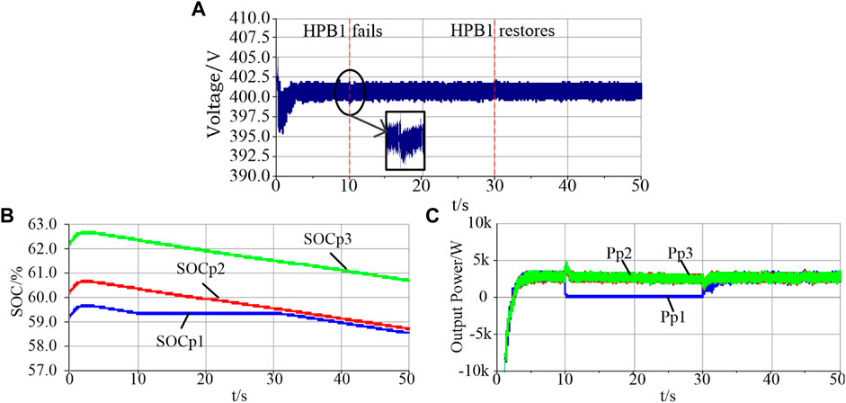
FIGURE 13. Simulation results when No. 1 High-Power Battery fault: (A) Bus voltage; (B) High-Power Battery SOC; (C) Output power of High-Power Battery).
Figure 13A shows that when it comes to 10 and 30 s, the cut and input of No. 1 High-Power Battery only causes a small impact on the bus voltage. Figure 13B shows that SOC of No. 1 High-Power Battery remains unchanged after failure, while the decline rate of other High-Power Battery increases. After the No. 1 High-Power Battery is repaired and put into operation in 30 s, the SOC of the three groups of High-Power Battery is still in the free charging/discharging zone, so it quickly keeps in sync. It can be seen from Figure 13C that the other two groups of High-Power Battery respond quickly at the moment of the cut and input of No. 1 High-Power Battery. Simulation results show that the remaining energy storage under the proposed control strategy can still work normally and respond to the expected power when some High-Power Batteries fail.
Failure of a High-Energy Battery
Under the same condition of section 4.2, replace the fault unit with No. 1 High-Energy Battery. The simulation results are shown in Figure 14.
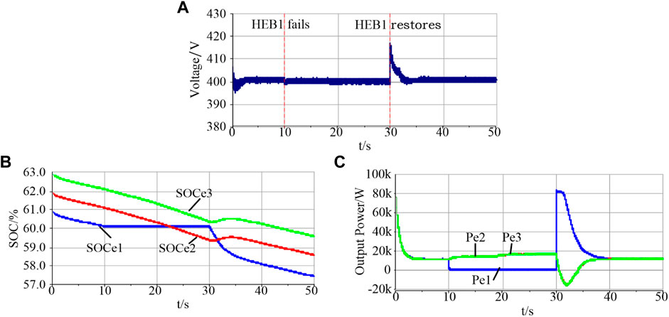
FIGURE 14. Simulation results when No. 1 High-Energy Battery fault: (A) Bus voltage; (B) High-Energy Battery SOC; (C) Output power of High-Energy Battery).
The results in Figure 14 are similar to Figure 13, but more volatile. The main reason is that the High-Energy Battery has to bear more power in normal operation, and the impact on the system during cutting and input is also greater. But bus voltage deviation is still within a reasonable range, it’s not more than 5% and soon returns to the normal reference voltage. The proposed method is robust to partial energy storage element faults.
Experimental Verification and Result Analysis
A microgrid model was established in the laboratory for verification. The analog diesel generator cabinet and analog wind generator cabinet are used as the power supply, the switching frequency of the energy storage bidirectional DC/DC converter is 10 kHz, the load is a programmable DC load, HEB is lithium iron phosphate battery, HPB is supercapacitor and other control parameters are the same as the simulation model. The experimental results are shown in Figures 15, 16.
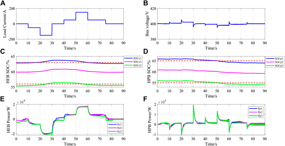
FIGURE 15. Experimental results of DC microgrid in step load change: (A) Load current; (B) Bus voltage; (C) High-Energy Battery SOC; (D) High-Power Battery SOC; (E) Output power of High-Energy Battery; (F) Output power of High-Power Battery).
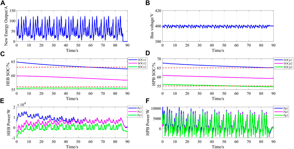
FIGURE 16. Experimental results of DC microgrid in renewable energy generation: (A) Renewable energy output; (B) Bus voltage; (C) High-Energy Battery SOC; (D) High-Power Battery SOC; (E) Output power of High-Energy Battery; (F) Output power of High-Power Battery).
It can be seen from Figures 15, 16A and Figures 15, 16B that after power fluctuation, the bus voltage can be quickly restored to stability with small voltage fluctuation. Figures 15, 16E and Figures 15, 16F show the output power changes of HEB and HPB. As can be seen from the figure, the change of HEB is relatively slow, while the response of HPB to power fluctuation is fast, which is in line with the design goal of the control strategy. Combined with the SOC change curves in Figures 15, 16C and Figures 15, 16D, it can be seen that the power curve of energy storage when SOC is higher than the limited range moves upward, that is, the discharge power is higher while the charge power is lower. When SOC is below the limit range, the power curve of energy storage moves downward, that is, the discharge power is lower while the charge power is higher. This shows that the proposed control strategy can effectively carry out SOC balancing.
Conclusion
Aiming at the problem that the traditional distributed multi-HESS cooperative control method of DC microgrid relies heavily on external communication, a communication free dynamic cooperative control strategy based on SOC is proposed. The simulation and experiment results show that the proposed control strategy has the following advantages: 1) being able to adjust the power distribution within HES module and among HES modules meet the needs of large-scale distributed new energy generating sets and loads; 2) using HPB to respond to the high frequency component of the bus voltage fluctuation, and using HEB to compensate the insufficient power of HPB to realize the optimization of HEB charge-discharge current, so as to effectively reduce the number of HEB charge-discharge mode change and prolong its service life; 3) reducing the dependency on communication among HES modules, thus improving the reliability of DC microgrid in island mode. However, this method does not take into account the impact of energy storage element aging, such as SOC estimation errors and reduced maximum output power due to declining energy storage life. How to consider these aspects under the condition of minimal communication requirements will be the focus of future research.
Data Availability Statement
The raw data supporting the conclusions of this article will be made available by the authors, without undue reservation.
Author Contributions
HL completed the theoretical derivation, modeling and simulation, data analysis and full text drafting of the project. YZ and YX provided research direction, theoretical guidance and paper revision. LF provided theoretical guidance, financial and site support.
Funding
This work was supported by the National Natural Science Foundation of China under Grant 51877211.
Conflict of Interest
The authors declare that the research was conducted in the absence of any commercial or financial relationships that could be construed as a potential conflict of interest.
Publisher’s Note
All claims expressed in this article are solely those of the authors and do not necessarily represent those of their affiliated organizations, or those of the publisher, the editors and the reviewers. Any product that may be evaluated in this article, or claim that may be made by its manufacturer, is not guaranteed or endorsed by the publisher.
References
Chen, H., Zhang, Z., Guan, C., and Gao, H. (2020). Optimization of Sizing and Frequency Control in Battery/supercapacitor Hybrid Energy Storage System for Fuel Cell Ship. Energy 197, 117285. doi:10.1016/j.energy.2020.117285
Chen, M., Zhao, X., Jin, X., Liu, J., and Wu, X. (2016). Research on Parallel Technology of Compound Energy Storage Device in DC Microgrid [J]. Trans. China Electrotechnical Soc. 31 (a02), 142–149. doi:10.19595/j.cnki.1000-6753.tces.2016.s2.016
Chen, X., Shi, M., Zhou, J., Chen, Y., Zuo, W., and Wen, J. (2019). Distributed Cooperative Control of Multiple Hybrid Energy Storage Systems in a DC Microgrid Using Consensus Protocol[J]. IEEE Trans. Ind. Electro., 1968–1979. doi:10.1109/TIE.2019.2898606
Chiang, P. H., Chiluvuri, S. P. V., Dey, S., and Nguyen, T. Q. (2017). “Forecasting of Solar Photovoltaic System Power Generation Using Wavelet Decomposition and Bias-Compensated Random Forest[C],” in 2017 Ninth Annual IEEE Green Technologies Conference (GreenTech), Denver, CO, USA, 29–31 March 2017.
Hoang, K. D., and Lee, H.-H. (2019). Accurate Power Sharing with Balanced Battery State of Charge in Distributed DC Microgrid. IEEE Trans. Ind. Electron. 66 (3), 1883–1893. doi:10.1109/tie.2018.2838107
Kathiresan, J., Natarajan, S. K., and Jothimani, G. (2020). Energy Management of Distributed Renewable Energy Sources for Residential DC Microgrid Applications[J]. Int. Trans. Electr. Energ. Syst. 30 (3), e12258. doi:10.1002/2050-7038.12258
Kotra, S., and Mishra, M. K. (2019). “Design and Stability Analysis of DC Microgrid with Hybrid Energy Storage System[J]. IEEE Trans. Sustain. Energy PP (3), 1-1.1603-1612. doi:10.1109/TSTE.2019.2891255
Li, J., Rui, X., Yang, Q., Liang, F., and Zhang, M. (2016). Design/test of a Hybrid Energy Storage System for Primary Frequency Control Using a Dynamic Droop Method in an Isolated Microgrid Power System[J]. Appl. Energ. 201, 257. doi:10.1016/j.apenergy.2016.10.066
Manandhar, U., Ukil, A., Kollimalla, S. K., and Gooi, H. B. (2015). “Application of HESS for PV System with Modified Control Strategy[C],” in 2015 7th IEEE Innovative Smart Grid Technologies Conference-ISGT Asia, Bangkok, Thailand, 3–6 Nov. 2015.
Mathews, M. A., and Rajeev, T. (2020). “Fuzzy Based Management of Hybrid Energy Storage System for Improved Dynamic Response of DC Microgrid[C],” in 2020 IEEE International Conference on Power Electronics, Smart Grid and Renewable Energy (PESGRE), Cochin, India, 2–4 Jan. 2020.
Ming, Y. U., Wang, Y., and Li, Y. G. (2017). Virtual Inertia Control of Hybrid Energy Storage in DC Microgrid Based on Predictive Method[J]. Power Syst. Tech. 41 (5), 7. doi:10.13335/j.1000-3673.pst.2016.1947
Musilek, P., Krömer, P., Martins, R., and Hesse, H. C. (2017). “Optimal Energy Management of Residential PV/HESS Using Evolutionary Fuzzy Control[C],” in 2017 IEEE Congress on Evolutionary Computation (CEC), Donostia, Spain, 5–8 June 2017.
Rahimi, M., and Ghadiriyan, S. (2019). A Generalized Droop-Based Compensator for Addressing the Issues Raised in a DC Microgrid Comprising Hybrid Wind-Battery-Back up Generation Sources[J]. Int. Trans. Electr. Energ. Syst. 29 (9), e12052. doi:10.1002/2050-7038.12052
Singh, P., and Lather, J. S. (2021). Power Management and Control of a Grid-independent DC Microgrid with Hybrid Energy Storage System. Sustainable Energ. Tech. Assessments 43, 100924. doi:10.1016/j.seta.2020.100924
Song, W., Chen, Y., Zhang, Y., Wen, A., and Wei, C. (2019). Bidirectional Boost Converter for High‐power Transmission Between Energy Storage Battery and DC Microgrid. Electron. Lett. 55 (7), 402–404. doi:10.1049/el.2018.7561
Su, H., Zhang, J., Wang, N., and Guo, W. (2018). Energy Management Strategy of High Capacity Hybrid Energy Storage System Based on Hierarchical Optimization[J]. High-Voltage Tech. 44 (4), 1177–1186. doi:10.7500/AEPS20160729015
Wang, Y., Hei, Y., Fu, Y., Wu, Z. K., and Yang, P. H. (2017). Adaptive Virtual Inertia Control of Dc Distribution Network Based on Variable Droop Coefficient[J]. Automation Electric Power Syst. 41 (8), 116–124. doi:10.19595/j.cnki.1000-6753.tces.171119
Wu, T., Ye, F., Su, Y., Wang, Y., and Riffat, S. (2020). Coordinated Control Strategy of DC Microgrid with Hybrid Energy Storage System to Smooth Power Output Fluctuation. Int. J. Low-Carbon Tech. 15 (1), 46–54. doi:10.1093/ijlct/ctz056
Zhang, J. H., Wang, H. M., Wei, Y. L., et al. (2018). The Layered Control Strategy of Dc Micro-grid Bus Voltage Fluctuation Including Composite Energy Storage and Gas Turbine Generator[J]. Trans. China Electrotechnical Soc. 33 (6), 1238–1246.
Zhou, G., Tian, Q., Leng, M., Fan, X., and Bi, Q. (2020). Energy Management and Control Strategy for DC Microgrid Based on DMPPT Technique. IET Power Electro. 13 (4), 658–668. doi:10.1049/iet-pel.2019.0383
Keywords: DC microgrid, distributed access, multi-hybrid energy storage system (multi-HESS), dynamic balance of SOC, renewable energy
Citation: Li H, Fu L, Zhang Y and Xiong Y (2022) A Dynamic and Cooperative Control Strategy for Multi-Hybrid Energy Storage System of DC Microgrid Based on SOC. Front. Energy Res. 9:795513. doi: 10.3389/fenrg.2021.795513
Received: 15 October 2021; Accepted: 20 December 2021;
Published: 24 January 2022.
Edited by:
Haoran Zhao, Shandong University, ChinaReviewed by:
Yuji Zeng, Dalian Maritime University, ChinaBo Wang, University of New South Wales, Australia
Salman Hajiaghasi, Shahid Beheshti University, Iran
Copyright © 2022 Li, Fu, Zhang and Xiong. This is an open-access article distributed under the terms of the Creative Commons Attribution License (CC BY). The use, distribution or reproduction in other forums is permitted, provided the original author(s) and the copyright owner(s) are credited and that the original publication in this journal is cited, in accordance with accepted academic practice. No use, distribution or reproduction is permitted which does not comply with these terms.
*Correspondence: Hao Li, MTgzNTE5MzAxODlAMTYzLmNvbQ==
 Hao Li
 Lijun Fu
