
95% of researchers rate our articles as excellent or good
Learn more about the work of our research integrity team to safeguard the quality of each article we publish.
Find out more
ORIGINAL RESEARCH article
Front. Energy Res. , 21 January 2022
Sec. Process and Energy Systems Engineering
Volume 9 - 2021 | https://doi.org/10.3389/fenrg.2021.793557
This article is part of the Research Topic Green and Sustainable LNG Supply Chain: A Bridge to a Low Carbon Energy Society View all 5 articles
 Muhammad Usman
 Yong Ki Kim*
Future energy systems will comprise 100% renewable energy and involve high integration of energy systems. District heating (DH) and cooling systems will be an undeniable part of future energy systems, as they facilitate high-efficiency, low-cost, and clean production. Low-temperature district heating (LTDH) is one of the candidates for future district heating systems, where the supply temperature is 60°C or below. Reducing heat losses from the pipe network in DH systems is challenging. Improving the insulation standards in DH pipes can decrease heat and temperature losses in the pipe networks. This study employs computational fluid dynamics to evaluate the optimum insulation thickness based on the material and digging costs in South Korea. A micro hybrid DH system with natural gas run fuel cell, heat pump and solar thermal is proposed in this study. An evaluation of the system with a 500 m pipe network system supplying hot water at 60°C with polyethylene, ethylene propylene diene monomer rubber, and polyurethane as insulation materials using ANSYS Fluent 17.2 shows that the heat losses are minimal when using PU foams. A cost estimation analysis showed that 32 mm was the optimum insulation thickness for achieving heat losses below 20 W/m and minimum material and digging costs when burring the pipeline network in the ground.
Decreasing fossil fuel sources and extreme weather changes due to global warming have accelerated the search for future sustainable energy systems, including 100% renewable systems (Alberg Østergaard et al., 2010; Mathiesen et al., 2014; Gatt et al., 2020). Energy consumption in areas such as manufacturing, buildings, transportation, and agriculture has recently received considerable attention because of the high rate of heat losses associated with them. The building sector, which consumes 20% of the total global energy, with an expected annual increase of 1.4% between 2012 and 2040 (U.S. Energy Information Administration (EIA)1), tops this list. A significant portion of building energy consumption is from space heating, which is approximately two times that of other consumption sources such as cooking, water heating, and refrigeration (Kaynakli, 2008).
Natural gas is one of the best sources to reduce the carbon emissions and transition towards green building concept (Abánades, 2018; Mohammad et al., 2021). Centralized production facilities mainly provide space heating in buildings through a heat transfer network called district heating (DH). The thermal energy is distributed through a pipe network that connects the thermal generation facility with the different building consumption nodes integrated with the system (Werner, 2013). Most of the world’s DH systems are currently based on the technologically advanced fourth-generation district heating (4GDH) system also called low-temperature district heating, where the supply temperature is 60°C and below (Lund et al., 2014; Lund et al., 2018). The primary fuel to run such systems is the natural gas. Reducing the supply temperature reduces the rate of heat losses from the system, which subsequently increases the supply and distribution efficiency and integrates low-temperature renewable energy and waste heat sources (Alberg Østergaard et al., 2010; Brocklebank et al., 2018).
Many countries worldwide have been promoting 4GDH system projects to improve energy efficiency and reduce greenhouse gas emissions (Case studies of Low Temperature District Heating systems, 2020). Network transmission and distribution heat losses are key factors in the design of cost-effective low-energy DH systems. The heat losses in DH occur from the envelope of the dwellings or during the transmission of hot water. Therefore, proper insulation in buildings and piping systems is important for energy savings and undesirable emission reduction from burning fossil fuels. There have been many studies on thermal insulation in the literature (Lund and Mohammadi, 2016). Various thermal insulation materials are currently used in DH networks, including polyethylene (PEX), ethylene propylene diene monomer rubber (EPDM), and polyurethane (PU). Milad et. performed computational thermal hydraulic performance analysis for various future DH schemes with PUR as insulation material (Khosravi and Arabkoohsar, 2019). Ali et al. proposed the optimum insulation thickness of pipes used in DH pipeline networks with rock wool as insulation material (Keçebaş et al., 2011), and Zukowski determined heat losses from pipelines (Zukowski, 2020). Danielewicz presented a numerical model of heat losses from the pre-insulated DH pipes buried in the ground (Danielewicz et al., 2016).
In South Korea, the heating is mainly provided through traditional oil or natural gas run boiler systems, only few newly developed cities and towns have implemented third-generation DH systems. The upcoming government policies are focused towards the low temperature district heating implementation. For that reasons few authors have recently studied the insulation materials and related heat losses when used for low temperature district heating pipes. Kim et al. performed a simulation to evaluate the surface temperature change based on the insulation thickness (Kim et al., 2020). In another study, the insulation surface temperature and energy losses were compared (Kim et al., 2021). However, studies that deal with low-temperature district heating (LTDH) implementation and associated challenges could not be found.
The present study examines the feasibility of PEX, EPDM rubber, and PU foam insulation materials for implementing LTDH in a demonstration site that supplies heat load to buildings from a hybrid smart energy system. CFD analysis was performed to evaluate the heat losses in each insulation material with varying thicknesses, and cost estimation evaluated the material and digging costs. The combined results demonstrate that an optimum insulation thickness of 32 mm using PU foam can reduce heat loss to below 20 W/m.
Hybrid energy systems are getting attention because of the building heat demand difference during winter and summer seasons (Sharafi et al., 2015; Ali and Jang, 2020). There have been many studies and demonstrations on such systems (Ataei et al., 2015; Mokhtara et al., 2021). The Korean government is incentivizing hybrid energy system and LTDH implementation to encourage renewable heating systems and reduce network heat losses (Baek et al., 2015; Kim, 2017; South Korea supports District Energy in Cities Initiative, 2019). The Korea Institute of Civil Engineering and Building Technology (KICT) has launched a project to develop an integrated system to satisfy the heating requirements at a building site. Figure 1 summarizes the proposed hybrid energy system comprising 470 solar panels, 10 kW fuel cells, and 84 kW geothermal heat pumps to manage the heat load at the site. The Solar System will be installed on the parking space available in the vicinity of the KICT. One goal of installing the Solar System on parking space is the performance assessment of low temperature heating pipes i.e. the heat losses from the pipes when the hot water travels at a distance far from the target building. The additional goal of this is to provide shadow to the parked cars of the employees. The production capacity of the Solar System is calculated to be 261,500 kW h. The heat produced from the Solar System is transferred to the thermal storage system (4a) via primary networking system. The storage capacity of the thermal storage system (4a) is 40 ton. From where the hot water produced will be supplied to building 5(a) via secondary networking system. The fuel cell and heat pump systems will be installed in the basement of the building (5b). The fuel cell is operated utilizing natural gas and the main output of the fuel cell is electricity. The waste water produced by the fuel cell which is at the temperature of about 60–70°C is utilized to supply the heating demand of building (5b). The heat pump works on the principle of a thermodynamic heat cycle. The hot air produced from the heat pump will be transferred to heat up the water from the thermal storage system (4b) via heat exchanger through primary networking system. During the winter season, when the heating demand of building 5(b) increases, the excess hot water produced from the solar thermal system and stored at thermal storage 4(b) is supplied to heat building 5(b). The length of the hot water distribution network is approximately 500 m, and a low-temperature heating network is installed to supply this heat. The ultimate goal of this project is to demonstrate that the LTDH in South Korea has network heat losses below 17%, as per the guidelines of the 4GDH. Because the current study is designed for demonstration purposes, the networking length is not as long as in the actual system. Therefore, the objective of the current study was to contain heat losses to below 20 W/m, which, when upgraded to larger systems (approximately 10 km networking length), can retain the heat losses to below 17%.
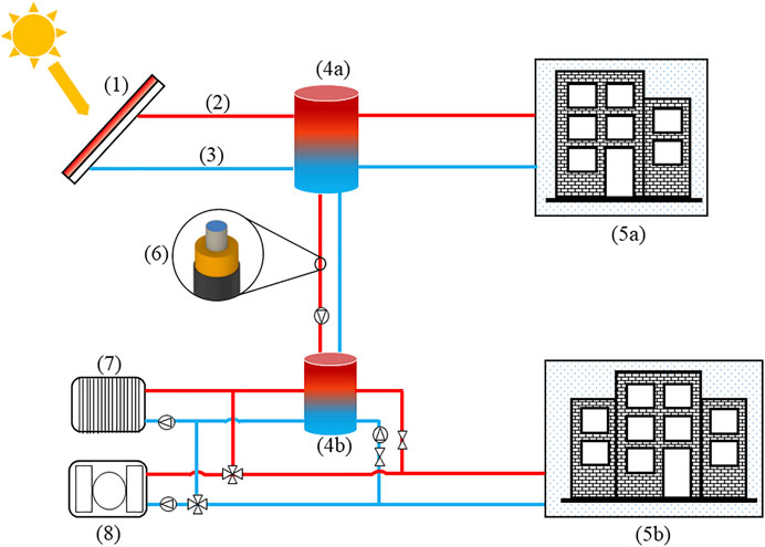
FIGURE 1. Micro District Heating System Demonstration Site proposed by KICT (1) Solar Thermal Collectors (2) Supply Pipe (3) Return Pipe (4a,b) Thermal Storage (5a,b) Target Building to Supply the Heat (6) Low-Temperature Pipe (7) Fuel Cell (8) Geothermal Source Heat Pump.
A typical insulation pipe was considered for this study. Table 1 lists the dimensions of the pipe components simulated in this study, and the characteristics of the heat-carrying pipe and medium are summarized in Table 2. Table 3 shows the thermal and physical properties of the three insulation materials evaluated in this study.
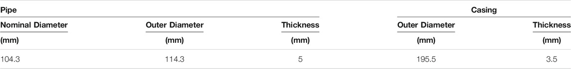
TABLE 1. Dimensions of carrier and jacket pipes.
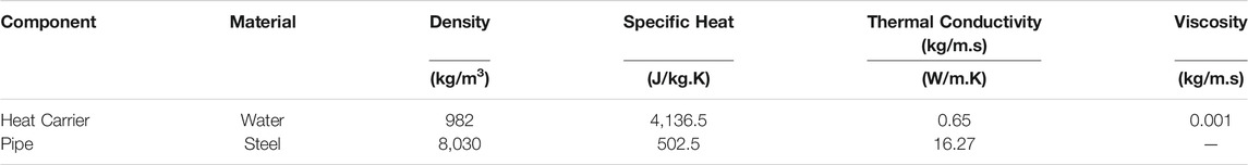
TABLE 2. Characteristics of Heat carrying medium and pipe.
TABLE 3. Thermal and physical properties of the three insulation materials and soil.
A numerical model of the pipeline with thermal insulation was developed using the ANSYS Release 17.2. Assumptions taken in this study were: incompressible flow, turbulent model (k-epsilon), no viscous heating, no inside heat generation, and same thermal properties during the flow. Absolute velocity formulation was used along with pressure based solver. A turbulent flow was assumed as the Reynolds number was higher than 20,000, and the standard K-epsilon (k-ε) turbulence model was used to simulate the mean flow characteristics. Velocity and pressure coupling was controlled by Semi- Implicit Method for Pressure-Linked Equations (SIMPLE). For pressure second Oder spatial discretization scheme was used, while for turbulent dissipation rate, turbulent kinetic energy and for discretization of momentum second Oder upwind scheme was used. The outlet was at zero gauge pressure. Figure 2 summarizes the numerical model and boundary conditions along with the dimensions considered in this study. A portion of the ANSYS model is also presented elaborating the walls with and without heat losses in Figure 2.
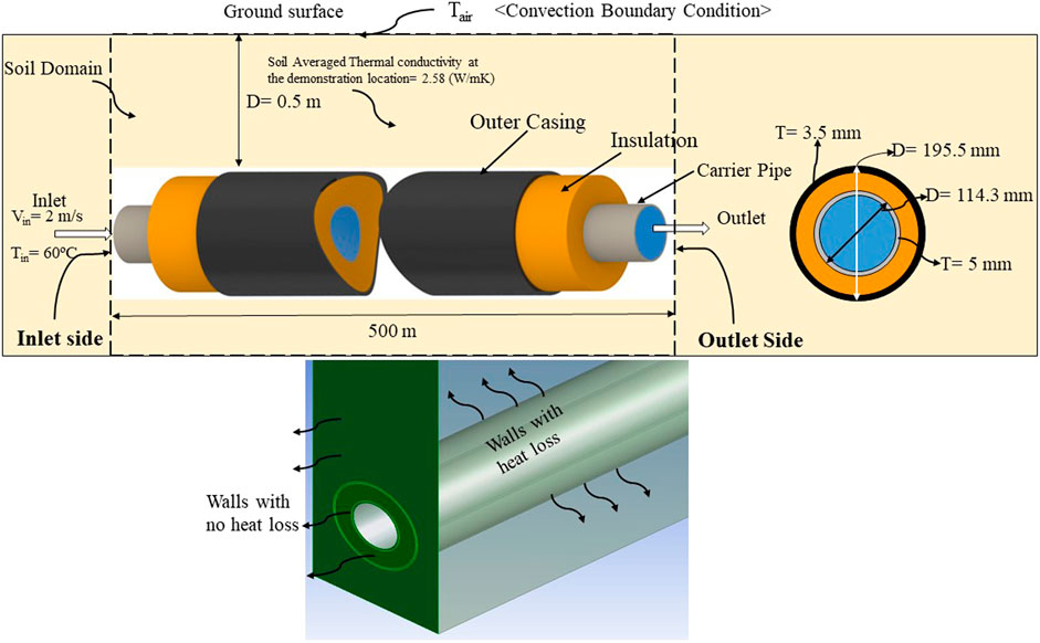
FIGURE 2. Schematic and the ANSYS model of the simulated computational domain along with boundary conditions.
Following governing equations were used for conservation of energy, mass, and momentum (Ahmad et al., 2013).
Where “k” is kinetic turbulence energy, “
For simplifying the model, the pipeline was assumed to have no bends. In addition, the inlet and outlet sides of the domain were declared as walls with zero heat flux to suitably compare the different types of insulation materials.
The computational domain is discretized by octagonal 3-D elements in a non-uniform grid. Considering the importance of the heat distribution along the radius of the pipe, the meshing has been done with very small elements. Table 4 gives information about three different mesh grids considered in the simulations.
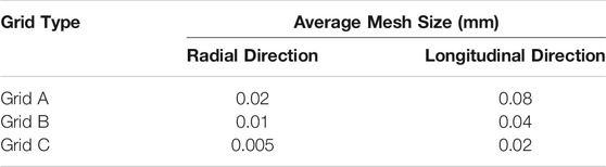
TABLE 4. Dimensions of mesh cells in different mesh grids.
Figure 3 compares the values obtained from the simulations with various mesh grid structures (A, B, C) for the rate of heat transfer from the pipes and those reported by the pipe manufacturer. Therefore, not only does this figure present the results of the sensitivity analysis on the mesh grids, but it also is a reference for the validity of the results of the simulations. A very good agreement was found between the results obtained from the simulations (in all the mesh grid sizes) and those reported by the Polytherm (HomePage2). The Grid type C was considered for the whole study because the results were closer to the data provided by the manufacturer.
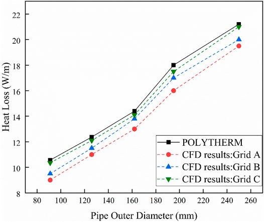
FIGURE 3. The mesh grid sensitivity analysis and validation of the CFD results.
Water enters the pipe at 60 °C and travels a distance of 500 m. Figure 4 shows the temperature drop of water as it travels along pipeline. The presented data is for the four seasons in South Korea with different insulation materials. The average temperature in each of the four seasons is shown in Table 5.
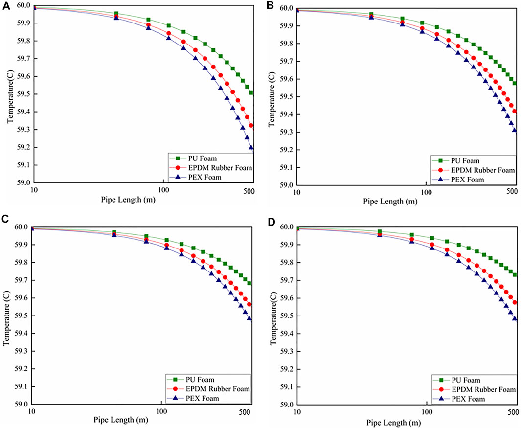
FIGURE 4. Average Temperature drop along the pipe length during.
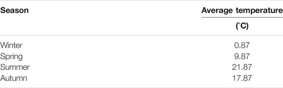
TABLE 5. Average seasonal temperatures in South Korea.
The temperature drop in winter is 0.52, 0.7, and 0.84°C, whereas that in spring is 0.43, 0.6, and 0.72°C for PU, EPDM, and PEX foam insulation materials, respectively. The temperature drop during summer and autumn was relatively lower than that during the winter and spring seasons because of the higher outdoor temperatures. The temperature drop for summer is 0.28, 0.44, and 0.54°C, whereas that in spring is 0.37, 0.51, and 0.6°C for PU, EPDM, and PEX foam insulation materials, respectively. For the same mass flow rate, a lower environmental temperature causes a larger temperature drop at the pipe outlet, resulting in a lower temperature drop during the summer seasons.
Figure 5 presents the contours of the temperature distribution in the radial direction at the pipe outlet including the soil domain for the three insulation materials. The portion of the soil domain is separately shown in the figure to better understand how the soil domain looks like at the outlet of the pipe. Since the maximum temperature drop occurs during the winter season, the contours are drawn only for this period when the average outside temperature is 1°C.
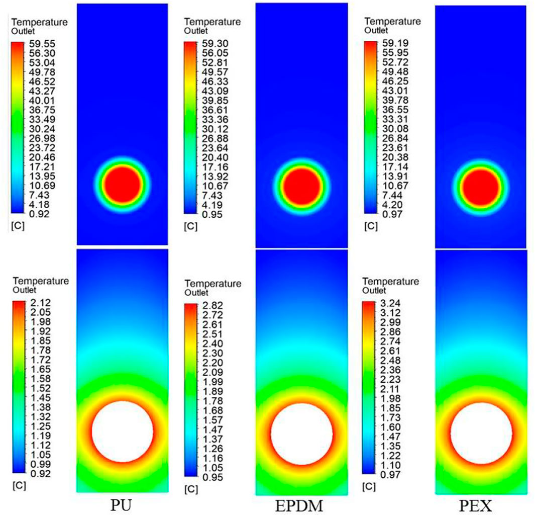
FIGURE 5. Contours of radial temperature distribution at the pipe outlet through the insulations including the soil domain during winter with (A) PU Foam (B) EPDM Rubber Foam (C) PEX Foam.
Figure 6 shows the monthly heat losses for different insulation materials for the entire year. The outdoor temperature is also plotted for each month. As expected, the heat loss decreases during summer and increases during winter. The percentage heat losses are lower in PU foam and higher in PEX foam insulation. The maximum heat loss occurs in February and has values of 1.49, 1.23, and 0.92% in PEX, EPDM rubber, and PU foam insulation. The average minimum temperature during February is −1°C. The heat loss is maximum during the start of the year (winter in South Korea). The heat loss curve decreases with an increase in outdoor temperature as the weather shifts to spring and summer and increases again as the outdoor temperature drops during autumn. The heat losses are maximum in PEX foam insulation and minimum in PU foam insulation. The EPDM rubber foam falls between the PU and PEX foams.
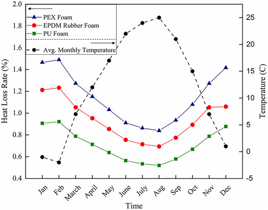
FIGURE 6. Monthly heat loss rate for different insulation materials and average monthly temperatures.
Figure 7 summarizes the total annual heat loss in the three insulation materials for the distribution network in Figure 1. The maximum heat loss was observed for the PEX foam, followed by EPDM rubber, and PU with values of approximately 1.1, 0.9, and 0.7%, respectively.
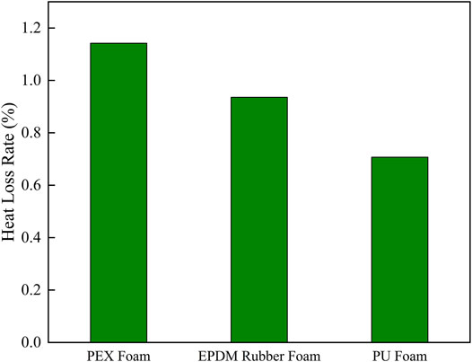
FIGURE 7. Annual heat loss rate in different insulation materials.
This section analyses the effect of varying the insulation thickness to reduce the heat losses in insulation materials with different thermal conductivity. Figure 8 illustrates the effect of insulation thickness on the total annual heat loss in the three insulation materials. The heat loss decreases as the insulation thickness increases in all cases. As the insulation thickness increases from 20 to 30 mm, the heat loss decreases by approximately 28, 27, and 29% in PEX foam, EPDM rubber foam, and PU foam, respectively. Similarly, an increase in the insulation thickness from 30 to 40 mm lowers the heat losses to 18, 19, and 20% in PEX foam, EPDM rubber foam, and PU foam, respectively. A significant reduction in heat loss is observed in the higher ranges of insulation thickness but at a reduced rate. The PU foam insulation shows the maximum heat loss reduction rate in the different insulation thicknesses range considered in this analysis.
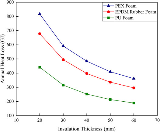
FIGURE 8. Effect of Insulation thickness on total annual heat loss for different Insulation Materials.
The main objective of lowering the operating temperature in DH systems is to decrease the rate of heat loss, which eventually reduces the cost of DH. However, it might be economically beneficial to reinforce insulations in transmission pipelines compared to existing standard pipes. This requires optimization based on techno-economic considerations to analyze reinforcement cost per meter of the pipe and resulting benefits.
The economic feasibility of different insulation materials is discussed in this section. A cost survey was conducted to estimate the materials and digging costs for three different types and sizes of DH pipes (한국물가정보3). Table 6 summarizes the material cost per meter and digging cost of the three insulation materials with varying thicknesses. Two types of digging costs are considered: soil digging and concrete digging. Concrete digging costs approximately four times more than soil digging because of the heavy machinery and skilled labor required.
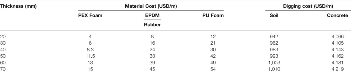
TABLE 6. Estimated material and digging cost for different insulation materials with varying thickness.
One of the primary goals of this study is to ensure the system’s economic feasibility by retaining the heat losses in the pipe to below 20 W/m. Because the demonstration site requires only soil digging, analysis was performed considering only the soil digging cost. The results are shown in Figure 9.
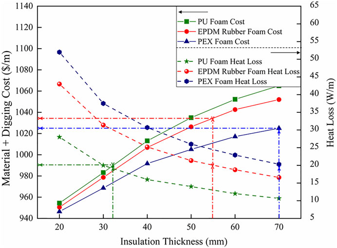
FIGURE 9. Effect of insulation thickness on material and digging cost vs heat losses.
The heat loss decreases with increasing insulation thickness, and the total cost increases with increasing insulation thickness for all materials. A heat loss of 20 W/m is obtained with PU foam insulation with a thickness of 32 mm and above. EPDM rubber foam with 55 mm insulation thickness also exhibits a heat loss below 20 W/m, whereas PEX foam requires an insulation thickness of 70 mm or above to achieve the same heat loss. The total cost per meter for PEX foam with 70 mm insulation is approximately USD 1010, whereas that of PU foam with 32 mm insulation thickness is approximately USD 990. The highest cost was found for the EPDM rubber foam, that is, USD 1035. The cost difference becomes relatively higher as the required pipe length is 500 m. Therefore, a PU form with an insulation thickness of 32 mm is proposed, considering optimum cost performance.
This study presents the heat loss analysis of a regular DH pipe used in a micro DH system demonstration site for implementing LTDH in South Korea. The heat loss analyses of such pipes for three insulation materials, the PEX foam, EPDM rubber foam, and PU foam insulations, are presented first. Subsequently, the effect of insulation thickness on heat loss and material and digging costs were investigated.
The results show that, as expected, the PU foam insulation shows a lower heat loss rate and temperature drop along the pipe, where the PEX foam insulation has the highest heat loss rate and temperature drop when the supply temperature was 60°C. PU insulation also showed a higher heat loss reduction rate than the EPDM rubber and PEX foam insulation materials.
The materials and digging cost estimation analysis with varying insulation thickness also supports PU foam with an insulation thickness of 32 mm as the ideal material for LTDH systems to maintain heat losses below 20 W/m.
The raw data supporting the conclusions of this article will be made available by the authors, without undue reservation.
Methodology, simulation, validation, writing—original draft preparation, MU; writing—review and editing, supervision, YK All authors have read and agreed to the published version of the manuscript.
This work was supported by the Korea Institute of Energy Technology Evaluation and Planning (KETEP) and the Ministry of Trade, Industry and Energy (MOTIE) of the Republic of Korea (No. 20173010140840).
The authors declare that the research was conducted in the absence of any commercial or financial relationships that could be construed as a potential conflict of interest.
All claims expressed in this article are solely those of the authors and do not necessarily represent those of their affiliated organizations, or those of the publisher, the editors, and the reviewers. Any product that may be evaluated in this article, or claim that may be made by its manufacturer, is not guaranteed or endorsed by the publisher.
LTDH, low temperature district heating; PEX, polyethylene; EPDM, ethylene propylene diene monomer; PU, polyurethane; CFD, computational fluid dynamics; 4GDH, fourth generation district heating; KICT, korea institute of civil engineering and building technology; SIMPLE, semi-implicit method for pressure-linked equations; UDF, user-defined function.
1https://www.eia.gov/index.php (Accessed August 9, 2021).
2https://www.polytherm.ie/ (Accessed November 14, 2021).
3http://www.kpi.or.kr (Accessed November 14, 2021).
Abánades, A. (2018). Natural Gas Decarbonization as Tool for Greenhouse Gases Emission Control. Front. Energ. Res. 6, 47. doi:10.3389/fenrg.2018.00047
Alberg Østergaard, P., Mathiesen, B. V., Möller, B., and Lund, H. (2010). A Renewable Energy Scenario for Aalborg Municipality Based on Low-Temperature Geothermal Heat, Wind Power and Biomass. Energy 35, 4892–4901. doi:10.1016/j.energy.2010.08.041
Ali, S., and Jang, C.-M. (2020). Optimum Design of Hybrid Renewable Energy System for Sustainable Energy Supply to a Remote Island. Sustainability 12, 1280. doi:10.3390/su12031280
Ataei, A., Nedaei, M., Rashidi, R., and Yoo, C. (2015). Optimum Design of an Off-Grid Hybrid Renewable Energy System for an Office Building. J. Renew. Sustain. Energ. 7, 053123. doi:10.1063/1.4934659
Baek, S., Kim, H., and Chang, H. (2015). Optimal Hybrid Renewable Power System for an Emerging Island of South Korea: The Case of Yeongjong Island. Sustainability 7, 13985–14001. doi:10.3390/su71013985
Brocklebank, I., Beck, S. B. M., and Styring, P. (2018). A Simple Approach to Modeling Rural and Urban District Heating. Front. Energ. Res. 6, 103. doi:10.3389/fenrg.2018.00103
Case studies of Low Temperature District Heating systems (2020). Celsius Initiative. Available at: https://celsiuscity.eu/case-studies-low-temperature-district-heating-systems/ (Accessed August 9, 2021).
Danielewicz, J., Śniechowska, B., Sayegh, M. A., Fidorów, N., and Jouhara, H. (2016). Three-dimensional Numerical Model of Heat Losses from District Heating Network Pre-insulated Pipes Buried in the Ground. Energy 108, 172–184. doi:10.1016/j.energy.2015.07.012
Gatt, D., Caruana, C., and Yousif, C. (2020). Building Energy Renovation and Smart Integration of Renewables in a Social Housing Block toward Nearly-Zero Energy Status. Front. Energ. Res. 8, 243. doi:10.3389/fenrg.2020.560892
Kaynakli, O. (2008). A Study on Residential Heating Energy Requirement and Optimum Insulation Thickness. Renew. Energ. 33, 1164–1172. doi:10.1016/j.renene.2007.07.001
Keçebaş, A., Ali Alkan, M., and Bayhan, M. (2011). Thermo-economic Analysis of Pipe Insulation for District Heating Piping Systems. Appl. Therm. Eng. 31, 3929–3937. doi:10.1016/j.applthermaleng.2011.07.042
Khosravi, M., and Arabkoohsar, A. (2019). Thermal-hydraulic Performance Analysis of Twin-Pipes for Various Future District Heating Schemes. Energies 12, 1299. doi:10.3390/en12071299
Kim, H., and 김희태, (2017). Optimal Hybrid Renewable Energy System in South Korea : Economic and Technical Feasibility Analysis of Micro Grids = 한국의 최적화 신재생에너지 하이브리드 시스템 연구 : 마이크로그리드의 경제적/기술적 타당성 분석을 중심으로. Available at: https://koasas.kaist.ac.kr/handle/10203/241729 (Accessed October 5, 2021).
Kim, S. E., Park, J. C., and Ryu, H.-K. (2020). Simulation of Surface Temperature Change by the Insulation Thickness of Hot Water Pipe in Building. KJACR 32, 21–26. doi:10.6110/KJACR.2020.32.1.021
Kim, S. E., Song, Y. W., and Park, J. C. (2021). Comparison of Insulation Surface Temperature and Energy Loss Based on the Location of a Hot-Water Pipe. KJACR 33, 25–30. doi:10.6110/KJACR.2021.33.1.025
Lund, H., Duic, N., Østergaard, P. A., and Mathiesen, B. V. (2018). Future District Heating Systems and Technologies: On the Role of Smart Energy Systems and 4th Generation District Heating. Energy 165, 614–619. doi:10.1016/j.energy.2018.09.115
Lund, H., Werner, S., Wiltshire, R., Svendsen, S., Thorsen, J. E., Hvelplund, F., et al. (2014). 4th Generation District Heating (4GDH). Energy 68, 1–11. doi:10.1016/j.energy.2014.02.089
Lund, R., and Mohammadi, S. (2016). Choice of Insulation Standard for Pipe Networks in 4 Th Generation District Heating Systems. Appl. Therm. Eng. 98, 256–264. doi:10.1016/j.applthermaleng.2015.12.015
Mathiesen, B. V., Connolly, D., Lund, H., Nielsen, M. P., Schaltz, E., Wenzel, H., et al. (2014). CEESA 100% Renewable Energy Transport Scenarios towards 2050. Technical Background Report Part 2. Department of Development and Planning. Aalborg University. Available at: https://vbn.aau.dk/en/publications/ceesa-100-renewable-energy-transport-scenarios-towards-2050-techn (Accessed August 9, 2021).
Mohammad, N., Mohamad Ishak, W. W., Mustapa, S. I., and Ayodele, B. V. (2021). Natural Gas as a Key Alternative Energy Source in Sustainable Renewable Energy Transition: A Mini Review. Front. Energ. Res. 9, 237. doi:10.3389/fenrg.2021.625023
Mokhtara, C., Negrou, B., Settou, N., Settou, B., and Samy, M. M. (2021). Design Optimization of Off-Grid Hybrid Renewable Energy Systems Considering the Effects of Building Energy Performance and Climate Change: Case Study of Algeria. Energy 219, 119605. doi:10.1016/j.energy.2020.119605
Sharafi, M., ElMekkawy, T. Y., and Bibeau, E. L. (2015). Optimal Design of Hybrid Renewable Energy Systems in Buildings with Low to High Renewable Energy Ratio. Renew. Energ. 83, 1026–1042. doi:10.1016/j.renene.2015.05.022
South Korea Supports District Energy in Cities Initiative (2019). Solarthermalworld. Available at: https://www.solarthermalworld.org/news/south-korea-supports-district-energy-cities-initiative (Accessed October 5, 2021).
Werner, S. (2013). “District Heating and Cooling,” in Reference Module in Earth Systems and Environmental Sciences (Elsevier), 841–848. doi:10.1016/B978-0-12-409548-9.01094-0
Keywords: low temperature district heating, oil and natural gas run boiler, pipe heat losses, CFD analysis, pipe insulation, optimum insulation thickness, cost estimation
Citation: Usman M and Kim YK (2022) Pipe Insulation Evaluation for Low-Temperature District Heating Implementation in South Korea. Front. Energy Res. 9:793557. doi: 10.3389/fenrg.2021.793557
Received: 12 October 2021; Accepted: 14 December 2021;
Published: 21 January 2022.
Edited by:
Muhammad Abdul Qyyum, Independent Researcher, Muscat, OmanReviewed by:
Absaar Ul Jabbar, National University of Sciences and Technology (NUST), PakistanCopyright © 2022 Usman and Kim. This is an open-access article distributed under the terms of the Creative Commons Attribution License (CC BY). The use, distribution or reproduction in other forums is permitted, provided the original author(s) and the copyright owner(s) are credited and that the original publication in this journal is cited, in accordance with accepted academic practice. No use, distribution or reproduction is permitted which does not comply with these terms.
*Correspondence: Yong Ki Kim, a2lteWtAa2ljdC5yZS5rcg==
Disclaimer: All claims expressed in this article are solely those of the authors and do not necessarily represent those of their affiliated organizations, or those of the publisher, the editors and the reviewers. Any product that may be evaluated in this article or claim that may be made by its manufacturer is not guaranteed or endorsed by the publisher.
Research integrity at Frontiers
Learn more about the work of our research integrity team to safeguard the quality of each article we publish.