 Fang Yingchao1
 Wang lin
- 1Southwest Pipe Company of Pipe China, Chengdu, China
- 2School of Mechatronic Engineering, Southwest Petroleum University, Chengdu, China
Under the special geological environment of the buried pipe, the ground is lost at the bottom of the pipe, which is created by various kinds of external factors. The pipe in the suspended state would be greatly deformed due to its own weight, internal pressure, and other factors, resulting in the failure of the pipeline. When a variable wall thickness weld occurs in the suspended section of the pipeline, the change of the pipeline stress will be more complicated and changeable. In this study, ABAQUS software is used to establish a pipe–soil model of variable wall thickness butt welds of suspended pipelines. The axial stress distribution with different affected factors in the pipe, the change of curvature, and Mises stress change of the entire pipe along the axial direction are obtained by analyzing the internal pressure, wall thickness ratio, suspended length, weld position, and cone length. The results show that the stress at the root of the weld changes significantly; therefore, the weld has a greater impact on the stress of the entire pipeline. The change of internal pressure has little effect on the stress at the pipe weld. As the suspended length increases, the change in stress at the weld is more obvious. When the weld seam is close to the soil, the support of the soil will gradually shift the maximum stress position of the pipe from the top of the pipe to the bottom of the pipe. With the increase in cone length, it will reduce the sudden change of pipe section and the change in stress effectively. The places where the curvature greatly changes along the axial direction are at the pipe–soil separation and the middle of the pipeline, while the stress reaches the maximum at the pipe–soil separation, and the place with the largest stress change is the weld in the middle of the pipeline.
Introduction
As the main transportation method of oil and natural gas, pipelines play an indispensable role in the petroleum industry. Mountains and hills occupy 1/3 of the total land area in China. The completed pipeline inevitably crosses various complex terrain conditions. Many pipelines are laid in areas with special geology or frequently washed by rain, so the pipelines are very sensitive to ground deformation. The soil loss will make buried pipelines suspended. Under the influence of external loads such as gravity and pipe–soil interaction, the pipeline will produce large deformation and stress concentration because of the large span of suspension (Nishida, 1967; Li et al., 2011; Ma et al., 2012; Terán et al., 2013; Dabiri et al., 2017; Zhu et al., 2017; Wang et al., 2018). The geological loads will cause large displacement, creep, and buckling and even cause the pipeline to rupture due to large deformation and cause pipeline leakage. In some special geological environments, the variable wall thickness often generates due to actual needs and economic aspects, and different wall thicknesses inevitably involve welding between pipelines. In the process of pipe production, pipe butt welds are usually made outside, although after welding, grinding and other operations are carried out to reduce stress concentration. However, due to the existence of variable wall thickness and sudden changes in the cross section, there will still be stress concentration and stress increase at the joints. The butt weld is the key part of fatigue. Fatigue cracking may occur at the root or toe of the weld (Lotsberg, 2009), thereby shortening the service life of the pipeline (Guo et al., 2019a; Guo et al., 2019b; Li et al., 2021) and affecting the reliability of the pipeline (Yuan et al., 2016; Yuan and Li, 2016; Yuan et al., 2018; Yuan et al., 2019).
Zhu et al. (2021) studied the response characteristics and mechanism of weld during deformation. Lotsberg (2009) proposed a more detailed formula for evaluating the stress concentration factor in the tube-packed structural parts based on the classical shell theory. Midawi et al. (2020) used indentation technology and DIC technology to measure the anisotropic behavior of weld metal yield strength, highlighting the importance of developing new technologies to characterize the local characteristics of welded structures. Liu et al. (2021) used Marc finite element software for numerical simulation, used the magnetic method for stress test, and obtained the stress distribution law of pipeline welding parts. There was large tensile stress near the welding area, which was easy to fracture and led to structural damage.
In practical engineering applications, it is difficult to measure stress at the weld due to the complex changes in stress (Dabiri et al., 2017). In this study, the finite element analysis method is used to analyze the axial stress of the variable wall thickness butt weld of the suspended pipeline. The axial stress of the pipeline is mainly generated by the internal pressure of the pipeline, followed by the force and moment generated by the dead weight and thermal expansion of the pipeline, or the force or moment generated by other forms of load (Z, 2009).
Among them,
When the pipeline is suspended, the pipeline always has certain bending due to the influence of external loads. The bending degree of the pipeline can be described by the curvature of the pipeline in the suspended state. The relationship between the curvature and the bending degree is described (Jian, 2015) as follows:
where K is the curvature (the positive and negative values of K represent the bending direction of the pipeline. The upward bending is positive, and the downward bending is negative) and U is the vertical displacement of the pipeline.
For the stress concentration factor, the ratio of the hot spot stress to the nominal stress is defined as the stress concentration factor, which can generally reflect the local stress status of the pipeline with the same stress. According to a large number of pipeline failure accidents, it indicates that the possibility of cracks increases greatly in areas with large stress or stress concentration factors. From the point of mechanics, the greater the stress, the higher will be the degree of stress concentration, and the probability of pipeline failure will increase. For the suspended pipeline with a variable wall thickness butt weld, the weld is the weakest part of the pipeline, so it is necessary to analyze the local position of the weld. On the basis of the classical shell theory, Lotsberg proposed a more detailed evaluation formula for the stress corrosion of tubular structures. The influence of manufacturing tolerance, thickness transition, and annular parts on the stress corrosion was verified by comparing with the finite element analysis results (Jian, 2015).
The suspended pipe with weld is studied in this work, which is a lack of research on suspended pipeline. The stress state of the variable wall thickness butt weld is studied by establishing the model of the variable wall thickness butt weld of suspended pipeline under self-weight and internal pressure load. The stress values are acquired by analyzing the internal pressure, wall thickness ratio, suspension length, weld position, weld cone length, and different curvatures, which are used to reflect the reliability of the variable wall thickness butt weld of suspended pipeline during operation. According to the change of stress, relevantly constructive suggestions are put forward for pipeline operation, which is of certain value for the safety evaluation of oil and gas pipelines.
Numerical Model
Model Assumption
The suspended pipelines are located in a complicate and changing external environment, in order to ensure the pertinence of the simulation model, and the single-factor analysis is adopted. At the same time, in order to ensure the accuracy of the results and the speed of calculation, the simplified assumptions are made in the model as follows:
(1) The base metal and welding material are ideally elastic–plastic materials, with equal intensity matching and no weld defects.
(2) Considering only internal pressure and self-weight load, the factors such as temperature, covering soil, fluid, and their influence with load are ignored.
(3) The pipeline is a straight pipe section and laid horizontally without difference of elevation in the vertical. The surrounding soil is isotropic and saturated.
(4) An ideal weld has variable wall thickness with a regular and uniform butt weld.
The finite element method is carried out by ABAQUS software, which has good ability to analyze non-linear problem. The butt weld model of the suspended pipeline with variable wall thickness is established by considering the non-linear coupling between the pipe and soil, and the large deformation of the pipe and soil.
Parameter Settings
Taking X80 pipeline steel, which is most commonly used in oil and gas pipelines as the research object, the relevant parameters are listed in Table 1:
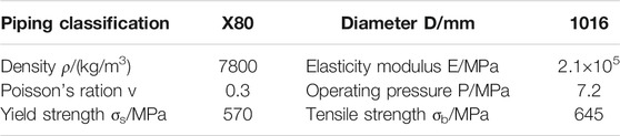
TABLE 1. Pipe parameters.
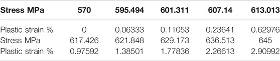
TABLE 2. Plastic stress and strain.
Mechanical properties of X80 pipeline steel were tested by using a universal testing machine, and the test was carried out according to Gao and Liang (2012). Tensile tests were carried out by a microcomputer-controlled universal testing machine to obtain stress–strain curves, as shown in Figure 1. One of the typical stress–strain data is selected as the constitutive relation of X80 pipeline steel, and the data are extracted. The Mohr–Coulomb model is adopted in the soil model, and the relevant parameters are listed in Table 3 (Jian, 2015).

FIGURE 1. Stress–strain curve.
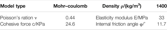
TABLE 3. Soil parameters.
Finite Element Model
In this study, the welding seam of the China–Myanmar natural gas pipeline is mainly V-type, double-sided, and butted groove, and the weld cross section is shown in Figure 2. The groove size can be found in Reference GB/T 985.2-2008, GB 50236-2011, GB 50251-2015, and other relevant standards.

FIGURE 2. Weld geometry model.
Among them, t1 and t2 are the thickness of the thin wall and thick wall, mm; α is the slope angle, 60°; b is the root gap, 3 mm; c is the thickness of the blunt edge, 3 mm; h is the weld residual height, 2 mm; β is the cutting angle (wall thickness transition angle), 60°; and w is the weld width of cover.
Considering the complexity of the weld grid, the field welding process, and other factors, the geometric model of the weld is appropriately simplified, at the same time, not considering the weld width of cover and residual height of weld root (It is supposed a linear transition).
The model of the suspended pipeline with a variable wall thickness butt weld is established on the basis of the aforementioned material parameters. The buried depth of the pipeline is 2.5 m. The initial weld is set in the middle of the suspended pipeline, and the soil length is 1/2 of the suspended length of the pipeline. The contact friction between the soil and pipe is penalty function, the normal friction coefficient is 0.5, and the tangential property is hard contact. The cross sections of both ends of the pipeline are symmetrical constraint along the normal direction. Symmetrical constraint along the normal direction is adopted for the side of the soil. The end face and undersurface of the soil are completely constrained, and the upper surface of the soil is completely free. Gravity load is applied to the whole pipe–soil model, and internal pressure load is applied to the pipe. The whole model is meshed by a hexahedral structure. Because the stress changes greatly at the weld of the pipeline, the mesh is encrypted by using the distributional method of single precision at the weld; besides, the part of soil close to the pipe–soil coupling is also encrypted. In order to improve the calculative efficiency, a 1/2 symmetric pipe–soil model is established for calculation. Figure 3 shows the boundary conditions of the pipe–soil model. Figure 4 shows the overall pipe-soil model.
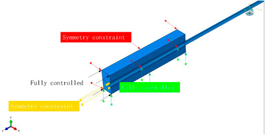
FIGURE 3. Pipe–soil boundary conditions model.
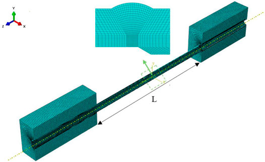
FIGURE 4. Pipe–soil model.
Model Verification
The feasibility verification of the model is usually carried out by comparing the experimental analysis with the theoretical results. For the model of the suspended pipeline with weld, due to the difficulty and cost of the experiment, the experimental data are scarce. Therefore, the feasibility of the model will be verified by comparing the theory with the finite element method.
In the calculation of the finite element, the ratio of hot spot stress to nominal stress is commonly used to define the stress concentration factor in engineering, as shown in the following formula (Wang et al., 2020):
Among them, Kt is the stress concentration factor;
In the early engineering practice, the reference to the empirical formula was mainly the formula proposed by Jian (2015):
Among them, t1 is the thickness of the thin wall, mm; t2 is the thickness of the thick wall, mm;
Afterward, Lotsberg deduced the stress concentration factor of weld under externally axial force by the shell theory, and the formulas have been modified by Lotsberg. The formulas are as follows (Lotsberg, 2009):
Among them, ν is Poisson ratio and e is the cone length of weld seam.
The results are shown in Table 4, comparing the results of stress by using the finite element method with the results of stress by using the empirical formula, as well as comparing the stress concentration coefficient with different wall thickness ratios, show that the maximum error is 5.8% and the error rate is small, which can ensure the accuracy of the analysis, and the pipe–soil model is feasible.

TABLE 4. Model verification.
Grid Independence Validation
The purpose of mesh independence verification is to verify the influence of the analytical results by using the finite element method with different mesh densities. Three different mesh densities are established, and the stress extracted from the weld root is compared with each other. The results are shown in Table 5, from the analysis of the comparative results, when dividing the grid with the density of mesh 1, the rate of error is large. (The rate of error is calculated based on the size of grid 2). When the grid reaches more than 100,000 level, the increase density of grid has little effect on the stress analysis. Therefore, the density of grid 2 is used to divide the model.
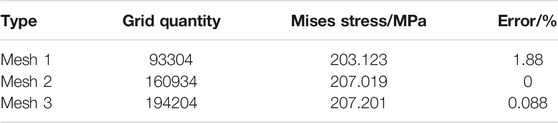
TABLE 5. Grid independence verification.
Results and Discussion
Through the analysis of the variable wall thickness butt weld model of the suspended pipeline, the values of axial stress are extracted from the weld root anticlockwise along the top of the pipeline to obtain the law of stress of the variable wall thickness butt weld model of the suspended pipeline.
Internal Pressure Effects
When analyzing the influence of internal pressure on the variable wall thickness butt weld of the suspended pipeline, the wall thickness ratio is t2/t1 = 1.2, the buried depth is 2.5 m, the suspended length of pipeline is 20D, and the soil length is 10D.The local stress nephogram is obtained from the bottom of the pipeline (Figure 5), which shows that the stress at the weld root of the pipeline is significantly greater than other parts at the bottom of the pipeline, due to the influence of the dual load of pipeline self-weight and internal pressure. The wall thickness of the conical part and the top of the weld has the tendency to change, and the stress is relatively small due to insufficient stress. The influence of internal pressure on axial stress of the weld with variable wall thickness is shown in Figure 6.
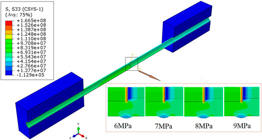
FIGURE 5. Stress nephogram influenced by internal pressure.
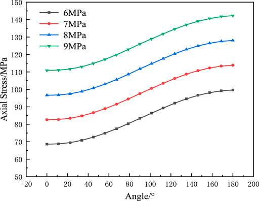
FIGURE 6. Internal pressure effects.
As can be seen from Figure 6, when the internal pressure increases from 6 to 9 MPa, the axial stress at the weld root increases gradually. When the internal pressure increases from 6 to 7 MPa, the stress increases about 17%. When the internal pressure increases from 7 to 8 MPa and then 8 to 9 MPa, the stress increases about 15 and 13%, respectively. Furthermore, under the same internal pressure, the difference of stress between the top and bottom of the pipeline is about 31 MPa.
Wall Thickness Ratio Effects
When analyzing the influence of the wall thickness ratio on variable wall thickness butt weld of the suspended pipeline, the operating pressure is 7.2 MPa, the buried depth is 2.5 m, the suspended length of pipeline is 20D, and the soil length is 10D. It can be seen from the local stress nephogram at the bottom of the pipeline (Figure 7), the stress is red, and the largest value is at the weld root. However, in the transition section of tapered wall thickness, the stress is blue. With the increase in the wall thickness ratio, the blue area of stress is also increasing in the conical transition section, and the stress difference between the welding root and the other parts is larger.
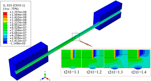
FIGURE 7. Stress nephogram influenced by wall thickness ratio.
The stress law is analyzed by changing different wall thickness ratios, as shown in Figure 8. When the wall thickness ratio increases from 1.1 to 1.4, the axial stress at the weld root tends to increase. When the wall thickness ratio increases from 1.1 to 1.2, the stress increases by 26%. When the wall thickness ratio increases from 1.2 to 1.3, the stress increases by 19%. When the wall thickness ratio increases from 1.3 to 1.4, the stress increases by 28 %. It indicates that the influence of the wall thickness ratio on pipeline stress cannot be ignored. At the same time, when the wall thickness ratio is increasing, the difference between the inner wall of the thin-walled pipeline and the thick-walled pipeline is also increasing, which will lead to the greater stress at the weld root and the more obvious stress concentration.
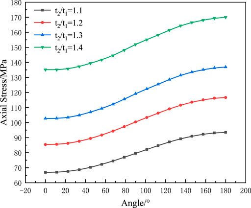
FIGURE 8. Wall thickness ratio effects.
Suspension Length Effects
When analyzing the influence of suspended length on the variable wall thickness butt weld of suspended pipeline, the operating pressure is 7.2 MPa, the buried depth is 2.5 m, the wall thickness ratio is 1.2, and the soil length is 1/2 times the length of suspended length. It can be seen from the local stress nephogram at the bottom of the pipeline that the maximum stress is at the junction of the welding root and the thick wall pipeline (Figure 9). With the increase in suspended length, the stress in the thin-walled pipe section increases gradually. Meanwhile, the stress at the transitional part of the cone is also gradually increasing. It indicates that with the increase in the suspended length, the deformation of the pipeline is increasing, and the stress will concentrate to the weakest part of the pipeline, and the stress of floating is more obvious at the changeable part of the pipe diameter.
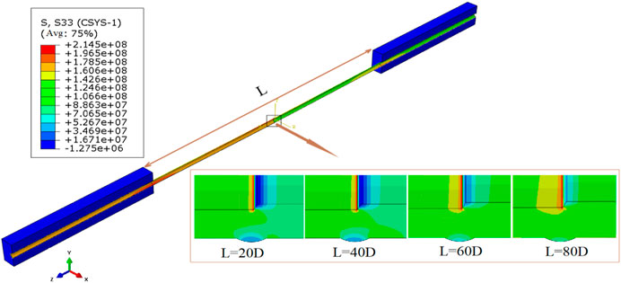
FIGURE 9. Stress nephogram influenced by suspension length.
Analyzing the stress law by changing the lengths of the suspended pipeline (20D, 40D, 60D, 80D) is shown in Figure 10. When the suspended length increases from 20D to 80D, the longer the suspended length of the pipeline, the greater is the stress variation amplitude at the top and bottom of the pipeline. When the suspended length is 20D, the stress difference between the top and bottom of the pipe at the welding root is about 31.27 MPa. When the suspended length is 40D, the stress difference between the top and bottom of the pipe at the welding root is about 93.03 MPa. When the suspended length is 60D, the stress difference between the top and bottom of the pipe at the welding root is about 216.33 MPa. When the suspended length is 80D, the stress difference between the top and bottom of the pipe at the welding root is about 382.96 MPa. It indicates that the longer the suspension, the more obvious is the gap of stress. As a result of the pipeline in a suspended state, the influence of gravity on the pipeline, the longer the suspended length, the greater will be the weight of the pipeline, and the deformation of the pipeline about bending and stretching will also increase. Nevertheless, at the top of the pipe, the tensile force of the weld with variable wall thickness decreases with the increase in the suspended length, so the stress at the weld root at the top of the pipe will gradually decrease. At the bottom of the pipeline, due to the dual load of gravity and tension, the stress of the weld with variable wall thickness changes greatly, and the degree of stress concentration will be more obvious, which will increase with the increase in the suspended length.
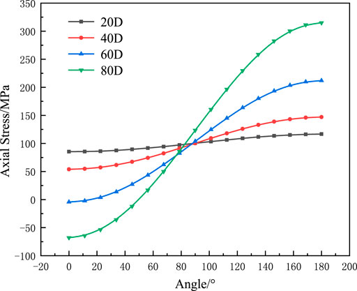
FIGURE 10. Suspension length effects.
Weld Position Effects
When analyzing the influence in the weld position on variable wall thickness butt welds of suspended pipelines, the operating pressure is found to be 7.2 MPa, the buried depth 2.5 m, the wall thickness ratio 1.2, the suspended length 40D, and the soil length 20D. From the stress nephogram at the top and bottom of the pipeline (Figure 11), it can be seen that the stress at the top of the pipeline decreases with the gradual transfer of the weld to the middle of the suspended pipeline, and the blue stress area increases significantly. At the same time, the stress at the weld root at the top of the pipeline changes from red to blue. At the bottom of the pipeline, the stress at the change of weld root and wall thickness is red, and the red area is also gradually widened, which belongs to the most vulnerable part of the pipeline. At the same time, the stress at the top of the weld increases with the right shift of the weld position.
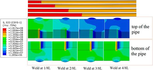
FIGURE 11. Stress nephogram influenced by weld position.
The stress law is analyzed by changing different welding positions (1/8L, 2/8L, 3/8L, and 4/8L), as shown in Figure 12. When the position of the pipeline weld moves from 1/8L to 4/8L, the farther the weld is away from the soil, the greater is the stress at the root of pipeline butt weld. When the welding position is at 1/8L, the stress difference between the top and bottom of the pipe at the weld root is about 17.36 MPa. When the weld position is at 2/8L, the stress difference between the top and bottom of the pipe at the weld root is about 46.96 MPa. When the weld position is at 3/8L, the stress difference between the top and bottom of the pipe at the weld root is about 83.31 MPa. When the weld position is at 4/8L, the stress difference between the top and bottom of the pipe at the weld root is about 92.32 MPa. It can be found from the stress diagram that when the weld seam is located at 1/8L, the stress at the weld root at the top of the pipeline is greater than that at the bottom of the pipeline. This is because at 1/8L, the pipe is close to the soil, the interaction between the pipe and the soil will have an impact on the stress of the pipeline. At this time, the stress change at the top of the pipe is larger than that at the bottom of the pipe. But when the weld position moves to the middle of the suspended pipeline as the position of the weld is farther and farther from the soil, the influence of the interaction between the pipe and the soil is gradually reduced, the position where the stress changes greatly return to the bottom of the pipe.

FIGURE 12. Weld position effects.
Weld Conical Surface Length Effects
When analyzing the influence of weld cone length on variable wall thickness butt weld of the suspended pipeline, the operating pressure is 7.2 MPa, the buried depth is 2.5 m, the wall thickness ratio is 1.2, the suspended length is 20D, and the soil length is 10D. It can be seen from the stress nephogram from the bottom of the pipeline that the stress gradient changes more and more evenly at the weld root (Figure 13), and the area with larger stress is gradually decreasing. The stress law is analyzed by changing the length of the weld cone (3.5, 4, 5, 6 mm), as shown in Figure 14. When the cone length increases from 3.5 to 6 mm, the stress at the weld root also decreases. When the cone length increases from 3.5 to 4 mm, the stress decreases by 0.16%. When the cone length increases from 4 to 6 mm, the stress decreases by 0.57%. When the cone length increases from 5 to 6 mm, the stress decreases by 1.13%. The influence of the cone length on the stress at the weld root decreases with the increase in the cone length because the degree of mutation will be reduced by increasing the cone length at the weld root at the inner wall of the pipe, and the cross-sectional stress distribution is more uniform.
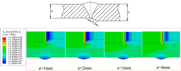
FIGURE 13. Stress nephogram influenced by weld conical surface length.
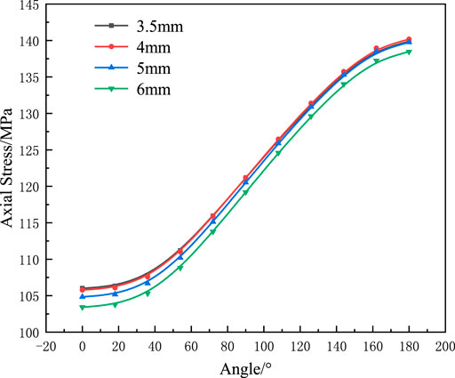
FIGURE 14. Weld conical surface length effects.
Pipeline Curvature Analysis
The model used to analyze the curvature is a suspended pipeline about 60 m in length. Through finite element analysis, it can be seen that the pipeline has been deformed significantly (Figure 15). Extracting the vertical displacement of each node at the bottom of the whole pipeline and calculating the curvature (Figure 16, where Fig. (A) and Fig. (B) are local graphs of points a and b). It can be seen that the curvature variation of point A and point B at the separation of pipeline and soil is obvious, where the curvature of point A is 0.001 and that of point B is 0.0009. The position with the largest curvature is the middle of the pipeline weld, and the curvature is 0.05987. Under the action of self-weight and internal pressure, the suspended part of the pipeline lacks the support of soil to the pipeline, which can only rely on the pipeline’s own ability to resist deformation. At both ends of the pipeline, due to the support of soil, the deformation of the pipeline is small, the curvature is relatively small, and the curvature variation in the rest are not obvious. The left side of the pipeline is a thin-walled pipe because its ability to resist deformation is less than the thick-walled pipe on the right side, resulting in a greater curvature at point A than at point B.
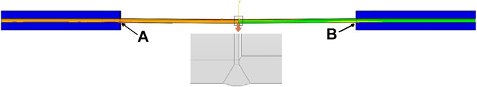
FIGURE 15. Pipeline deformation diagram.
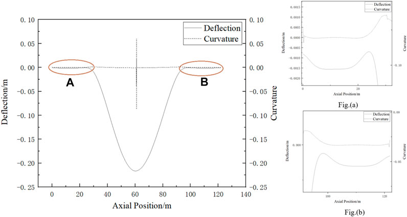
FIGURE 16. Deflection and curvature diagram, where Figure (a) and Figure (b) are local graphs of points A and B. Point A is the junction of thin-walled pipe and soil. Point B is the junction of thick-walled pipe section and soil.
As can be seen from Figure 17, in the pipe–soil separation part, the stress value at point A of the left thin-walled pipe section is 243 MPa, and the stress value at point B of the right thick-walled pipe section is 206 MPa. In the middle of the pipe, due to the existence of weld, the stress change of the pipe is greatly reduced from 202 to 155 MPa. For the Mises stress of the pipeline, the thin-walled pipe section has a large deformation due to its poor ability to resist deformation, and the stress of the whole thin-walled pipe section is larger than that of the thick-walled pipe section. The position with the largest curvature is not the position with the largest stress, and the position with the largest stress is not the position with the largest curvature. Only when the stress value changes greatly, the position with larger curvature changes.
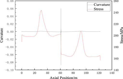
FIGURE 17. Curvature and strain diagram.
Through the analysis of various influencing factors, it can be known that the key factor is the suspended length. When the suspended length exceeds 60D, the increase in the stress value in the middle of the pipeline will gradually increase, so 60D is regarded as the critical value of suspension. In terms of internal pressure, the increase in internal pressure will elongate the pipe along the axial direction, and the axial stress will increase. In reference to the wall thickness ratio, the change in the wall thickness ratio affects the inner diameter at both ends of the weld. A larger wall thickness ratio makes the transition cone at both ends of the weld steeper and the stress concentration at the weld root more obvious. The suspended length will affect the dead weight of the pipeline; a larger suspended length will make the middle part of the pipeline bend gradually under the action of the dead weight, while the capacity of the soil at both ends to share the gravity of the pipeline does not increase. The larger suspended length of the pipeline will increase the deformation of the pipeline and the axial stress in the middle of the pipeline. In terms of the weld position factor, the change in the weld position affects the supporting effect of soil on the pipeline. The closer the weld is to the soil, the stronger willbe the supporting effect of soil, and the smaller will be the axial stress of the pipeline. As far as the weld cone length factor is concerned, the change in the weld cone length affects the transition between large and small pipe diameters. On the premise that the wall thickness ratio remains unchanged, the longer the cone length is, the gentler will be the wall thickness transition, and the axial stress will not increase sharply due to the sudden change of wall thickness.
Conclusion
The main studies of the work are about the influence of internal pressure, wall thickness ratio, suspended length, weld position, and cone length on the axial stress of the variable wall thickness butt weld of suspended pipeline and the analysis of curvature and stress at the weld root. Through the analysis of the finite element results, the following conclusions can be drawn as follows:
The influence of single change in internal pressure on weld stress is smaller than the other four factors.
The influence of the wall thickness ratio on the stress at the weld seam gradually increases with the increase in the wall thickness ratio. The larger the wall thickness ratio, the greater the difference between the inner diameters of the pipes at both ends, and the greater the stress change at the weld joint. Therefore, for variable wall thickness–welded pipelines, a small wall thickness ratio should be selected to increase the reliability of pipeline operation.
The increase in the suspended length will significantly change the stress at the weld root, and the stress difference between the top and bottom of the pipeline will also gradually increase. In a large suspended state, the probability of failure at the bottom of the pipeline is the largest. In practical engineering applications, large suspended pipeline should be avoided.
When the weld position is close to the soil, the soil can give a larger supporting force to the suspended pipeline, so the stress at the weld will be smaller than the weld position far from the soil.
With the increase in the cone length, the stress gradient at the welding root is more uniform, and the stress decreases. Increasing the cone length is conducive to reducing the cross-sectional mutation and sharing the stress change. When the pipeline is welded, maintaining a large cone length can reduce the failure rate of the pipeline during operation.
When the pipeline is suspended, the curvature at the separation of the pipeline and the soil is increasing, but when it moves to the suspended section, the curvature decreases gradually. When it reaches the weld position located in the middle of the pipeline, the curvature changes to the peak, and the stress value changes greatly. Therefore, the position where the stress value changes greatly is the position where the curvature changes most. In the separation of pipe and soil, the curvature has a certain change, but it is not obvious. However, in the separation of pipe and soil, the stress is the largest, and in the middle of the pipeline weld position, the stress change is the largest.
Data Availability Statement
The original contributions presented in the study are included in the article/Supplementary Material; further inquiries can be directed to the corresponding author.
Author Contributions
FY contributed to data curation, writing—original draft preparation, and writing—original draft. YD performed data curation and wrote the original draft. WB supervised the research and wrote the original draft. XJ worked on software. XH performed the validation. HH and WL contributed to writing—review and editing.
Funding
This work is supported by the research project of the Southwest Pipe Company of Pipe China (XNGD-JSZX-2020-JS-371-1).
Conflict of Interest
FY, YD, WB, XH, and HH were employed by the Southwest Pipe Company of Pipe China.
The remaining authors declare that the research was conducted in the absence of any commercial or financial relationships that could be construed as a potential conflict of interest.
Publisher’s Note
All claims expressed in this article are solely those of the authors and do not necessarily represent those of their affiliated organizations, or those of the publisher, the editors, and the reviewers. Any product that may be evaluated in this article, or claim that may be made by its manufacturer, is not guaranteed or endorsed by the publisher.
Abbreviations
A, cross-sectional area of the pipe; D, pipe diameter; F, axial fore on the pipe; K, curvature; Kt, stress concentration factor; M, bending moment of the pipe; P, internal pressure; U, vertical displacement of the pipeline; W, bending section coefficient; e, cone length of weld seam; t, wall thickness; t1, thickness of small diameter pipe; t2, thickness of large diameter pipe; v, Poisson ratio; σt, axial stress of the pipe; σhot, hot spot stress; σnom, nominal stress; δt, axis deviation value caused by the wall thickness transition; δm, pipe offset value.
References
Dabiri, M., Ghafouri, M., Raftar, H. R. R., and Björk, T. (2017). Neural Network-Based Assessment of the Stress Concentration Factor in a T-Welded Joint. J. Constructional Steel Res. 128, 567–578. doi:10.1016/j.jcsr.2016.09.024
Gao, Y. F., and Liang, X. B. (2012). GB/T 228.1-2010《Tensile Test of Metal Materials Part 1: Room Temperature Test method》Implementation Guide. Beijing: Standards Press of China.
Guo, J., Zheng, H., Li, B., and Fu, G. Z. (2019). A Bayesian Approach for Degradation Analysis with Individual Differences. IEEE Access 7, 175033–175040. doi:10.1109/access.2019.2955969
Guo, J., Zheng, H., Li, B., and Fu, G. Z. (2019). Bayesian Hierarchical Model-Based Information Fusion for Degradation Analysis Considering Non-competing Relationship. IEEE Access 7, 175222–175227. doi:10.1109/access.2019.2955932
Li, H., Guo, J. Y., Yazdi, M., Nedjati, A., and Adesina, K. A. (2021). Supportive Emergency Decision-Making Model towards Sustainable Development with Fuzzy Expert System. Neural Comput. Appl. 33, 15619–15637. doi:10.1007/s00521-021-06183-4
Li, Y., Lence, B. J., Shi-Liang, Z., and Wu, Q. (2011). Stochastic Fatigue Assessment for Berthing Monopiles in Inland Waterways. J. Waterway, Port, Coastal, Ocean Eng. 137 (2), 43–53. doi:10.1061/(asce)ww.1943-5460.0000063
Liu, W. L. Z. Y., Jiang, W. M., Wang, X. L., He, Y. Z., and Long, B. (2021). Numerical Simulation of Welding Residual Stress of X80 Pipeline Joint in Eastern China - Russia Railway. Oil Gas Storage Transp. Available at: https://kns.cnki.net/kcms/detail/13.1093.TE.20200611.1111.002.html.
Lotsberg, I. (2009). Stress Concentrations at Butt Welds in Pipelines. Mar. Struct. 22, 335–337. doi:10.1016/j.marstruc.2008.06.008
Ma, T., Wu, J., Tang, Y., Hu, H., and Li, A. (2012). Maximum Suspended Length of Production Pipeline. J. Southwest. Pet. Univ. Technol. Ed. 34 (4), 165–173. doi:10.3863/j.issn.1674-5086.2012.04.025
Midawi, A. R. H., Huda, N., Simha, C. H. M., and Gerlich, A. P. (2020). Characterization of Anisotropy of Strength in API-X80 Line Pipe Welds through Instrumented Indentation. Metallogr. Microstruct. Anal. 9, 884–894. doi:10.1007/s13632-020-00693-8
Terán, G., Albiter, A., and Cuamatzi-Meléndez, R. (2013). Parametric Evaluation of the Stress Concentration Factors in T-Butt Welded Connections. Eng. Struct. 56, 1484–1495. doi:10.1016/j.engstruct.2013.06.031
Wang, L., Bi, H., Yang, Y., Zhang, Y., and Li, Y. (2018). Response Analysis of an Aerial-Crossing Gas-Transmission Pipeline during Pigging Operations. Int. J. Press. Vessels Piping 165, 286–294. doi:10.1016/j.ijpvp.2018.07.011
Wang, L., Tang, Y., Ma, T., Zhong, J., Li, Z., Zhang, Y., et al. (2020). Stress Concentration Analysis of Butt Welds with Variable wall Thickness of Spanning Pipelines Caused by Additional Loads. Int. J. Press. Vessel. Pip. 182, 104075. doi:10.1016/j.ijpvp.2020.104075
Yuan, R., and Li, H. (2016). A Multidisciplinary Coupling Relationship Coordination Algorithm Using the Hierarchical Control Methods of Complex Systems and its Application in Multidisciplinary Design Optimization. Adv. Mech. Eng. 9, 168781401668522. doi:10.1177/1687814016685222
Yuan, R., Li, H., and Wang, Q. (2018). An Enhanced Genetic Algorithm–Based Multi-Objective Design Optimization Strategy. Adv. Mech. Eng. 10, 168781401878483. doi:10.1177/1687814018784836
Yuan, R., Meng, D., and Li, H. (2016). Multidisciplinary Reliability Design Optimization Using an Enhanced Saddlepoint Approximation in the Framework of Sequential Optimization and Reliability Analysis. Proc. Inst. Mech. Eng. Part. O J. Risk Reliab. 230, 570–578. doi:10.1177/1748006x16673500
Yuan, R., Tang, M., Wang, H., and Li, H. (2019). A Reliability Analysis Method of Accelerated Performance Degradation Based on Bayesian Strategy. IEEE Access 7, 169047–169054. doi:10.1109/access.2019.2952337
Z. F., S. (2009). Stress Analysis and Safety Research on Special Pipe Section of Gas Pipeline. East China: East China: China University of Petroleum.
Zhu, L., Luo, J., Wu, G., Han, J., Chen, Y., and Song, C. (2021). Study on Strain Response of X80 Pipeline Steel during weld Dent Deformation. Eng. Fail. Anal. 123, 105303. doi:10.1016/j.engfailanal.2021.105303
Keywords: variable wall thickness weld, suspended pipeline, finite element analysis, axial stress, curvature
Citation: Yingchao F, Dongliang Y, Binbin W, Jian X, Heng X, Hao H and lin W (2022) Stress Analysis of the Effect of Additional Load on the Butt Weld of Suspended Pipeline With Variable Wall Thickness. Front. Energy Res. 9:792508. doi: 10.3389/fenrg.2021.792508
Received: 10 October 2021; Accepted: 03 December 2021;
Published: 24 March 2022.
Edited by:
Jiang Bian, China University of Petroleum (East China), ChinaReviewed by:
Xiaoben Liu, China University of Petroleum, Beijing, ChinaYing Zeng, National University of Singapore, Singapore
Copyright © 2022 Yingchao, Dongliang, Binbin, Jian, Heng, Hao and lin. This is an open-access article distributed under the terms of the Creative Commons Attribution License (CC BY). The use, distribution or reproduction in other forums is permitted, provided the original author(s) and the copyright owner(s) are credited and that the original publication in this journal is cited, in accordance with accepted academic practice. No use, distribution or reproduction is permitted which does not comply with these terms.
*Correspondence: Wang Binbin, d2FuZ2JiQHBpcGVjaGluYS5jb20uY24=