- Department of Electrical Engineering, Nantong University, Nantong, China
With the increasing penetration of renewable energy generation, the frequency stability of a power grid can be significantly threatened. A doubly-fed induction generator (DFIG) participates in the frequency support of a power grid by releasing kinetic energy (KE) to boost the frequency nadir (FN). However, during rotor speed restoration, it is difficult to counterbalance the size of a second frequency drop (SFD) and the rotor speed recovery duration. This paper proposes an improved torque limit-based inertial control (TLBIC) to raise the FN by releasing less kinetic energy while guaranteeing rapid frequency stabilization with reduced SFD. To this end, when detecting a disturbance, the DFIG enhances the active reference power to the torque limit, and then the active power reduces smoothly based on an exponential function until the maximum power point tracking (MPPT) curve is met, and the rotor speed reverts to the initialization operating condition along the MPPT curve. A simulation system model with various wind power penetrations is established in EMTP-RV. Results show that the proposed scheme boosts the FN at a high level with less KE and guarantees rapid frequency stabilization.
Introduction
Recently, wind power generation has developed rapidly due to the shortage of fossil fuel and worsening environmental situations. Doubly-fed induction generators (DFIGs) are widely applied in the field of wind power because of the relatively low price, decoupling control operation of the active power and reactive power, maximum power point tracking (MPPT) control, deloading operation, and other advanced control strategies (Bao et al., 2020; Xiong et al., 2020). In addition, DFIGs are connected to the grid by power electronic converters, which decouple the rotor speed of the wind turbine from the system frequency. Consequently, DFIGs are unable to sustain the system frequency (Yang et al., 2022; Yang et al., 2021; Xiong et al., 2021a). With the increasing penetration level of wind power, the power system will face significant challenges in system frequency stability. Therefore, more and more attention has been paid to DFIG active frequency support (Wang and Tomsovic, 2018; Xiong et al., 2021b).
DFIGs supply inertial control using additional control strategies. In Kheshti et al. (2019), the most characteristic inertial control can be roughly divided into two types: virtual inertial control (PD control) (Morren et al., 2006; Fernandez et al., 2008; Lee et al., 2016; Van de Vyver et al., 2016; Li et al., 2017; Hu and Wu, 2019; Peng et al., 2020) and stepwise inertial control (Ullah et al., 2008; Lao, 2021). PD control emulates the inertia response and primary frequency response of synchronous generations (SGs) to provide a frequency response. Compared with PD control, stepwise inertial control can supply a rapid frequency response due to the operating characteristics of a DFIG (Kheshti et al., 2019). However, after DFIGs participate in frequency regulation by releasing rotor kinetic energy, the rotor speed will deviate from the optimal state corresponding to MPPT operation. Therefore, the rotor speed needs to regain the optimal state considering the economic benefits of the wind farm, but the speed recovery is accompanied by power mutation, which trend to cause a significant SFD (Xiong et al., 2021c).
In Hafiz and Abdennour (2015), the active power is designed as a slope function. Even though this scheme lessens the SFD to a certain extent, but it delays the rotor speed recovery. Furthermore, the parameters of this function in different scenarios need to be reset. In order to recover the rotor speed, a constant power reference is addressed (Kang et al., 2016a; Kang et al., 2016b). However, the tradeoff between the depth of an SFD and the rotor speed restoration is difficult to achieve. The study of Xu and Xu (2017) suggests a constant accelerating power reference based on the mechanical power curve, which realizes the smooth recovery of the rotor speed. Nevertheless, the mechanical power curve is difficult to acquire and SFD still exists due to the sudden power drop. The authors of (Lao, 2021) suggested a frequency regulation strategy based on logistic regression function, which realizes smooth rotor speed recovery. However, the function used in this strategy is too complex, and too many parameters need to be defined, which brings difficulties to engineering applications. To compensate for the energy required for rotor speed recovery, a coordinated frequency control strategy for the wind turbine and SG is addressed (Xu et al., 2018). The rotor speed recovery can be realized with reduced SFD by adjusting the primary frequency modulation parameters of the SG. However, for a large-scale power system with high wind power penetrations, this strategy is not economical to regain the rotor speed. In Wu et al. (2017), a frequency control strategy based on the energy storage system is suggested, which realizes the rapid speed recovery while eliminating the SFD. However, the overall operation and maintenance cost of the power system increases due to the high cost of the energy storage system.
To approach the above issues, this paper addresses an improved torque limit-based inertial control (TLBIC) scheme to raise the FN by releasing less rotational energy while guaranteeing rapid frequency stabilization with reduced SFD. To this end, when detecting a disturbance, the power reference of the DFIG increases to the torque limit. Afterward, the power reference decreases smoothly based on an exponential function until it the maximum power point tracking (MPPT) curve is met, and then the rotor speed reverts to the initialization operating condition along the MPPT curve. In addition, DFIGs are assumed to work in MPPT mode prior to frequency disturbance. The benefits of the proposed TLBIC scheme are verified under various wind power penetrations and wind speed conditions based on an EMTP-RV simulator.
Modeling of a Doubly-Fed Induction Generator
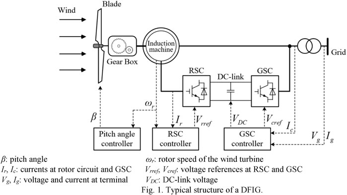
This section mainly introduces the typical structure of a DFIG, as illustrated in Figure 1 which includes a wind turbine model, two-mass shaft model, and DFIG controllers.
Wind Turbine Model
The mechanical input power captured by a wind turbine from moving air is represented as:
where cp represents the power coefficient; λ and β are the tip-speed ratio and pitch angle, respectively; ρ is the air density; A indicates the swept area by blade; R means the blade length and vw means the wind velocity.
As in (Kang et al., 2016a; Kang et al., 2016b), cp employed in Eq. 1 can be represented as:
where
and λ is given as:
where ωr represents the rotor speed of the generator.
For capturing more wind energy resources, the DFIG usually works in MPPT operation. As in Fernandez et al. (2008), the MPPT operation power reference, PMPPT, is expressed as:
where cp, max is a maximum value of cp when β = 0°, λ = λopt and set to 0.5 in this paper; λopt is the optimal λ of the wind turbine to capture the maximum wind energy and set to 9.95 in this paper; k is a calculation of the characteristic parameters of the wind turbine and set to 0.512 in this paper.
Two-Mass Shaft Model
This paper uses a two-mass shaft model to express the mechanical dynamics between the wind turbine and induction generator, the model can be represented as Eqs 6–9 in (Boukhezzar and Siguerdidjane, 2011).
where Jt and Jg are the inertia constants of the wind turbine and generator, respectively; Tm and Tem are the mechanical torque, electrical torque of the wind turbine and generator, respectively; ωt is the rotor speed of the wind turbine; TL and TH are the torques of the low-speed and the high-speed shafts, respectively; ωL is the rotor speed of the low-speed shaft; K is the spring constant; D is the damping constant; θ is the torsional twist; N is the gear ratio.
β: pitch angle ωr: rotor speed of the wind turbine.
Ir, Ic: currents at rotor circuit and GSC Vrref, Vcref: voltage references at RSC and GSC.
Vg, Ig: voltage and current at terminal VDC: DC-link voltage.
Control System of a DFIG
The control system consists of a pitch angle controller, a rotor-side controller (RSC) and grid-side controller (GSC). The pitch angle controller adjusts the pitch angle according to the current wind speed to ensure the maximum of DFIG output power on the premise of the stable operation. An RSC realizes active and reactive power decoupling control and MPPT control of the DFIG. The GSC is mainly responsible for maintaining the DC-link voltage.
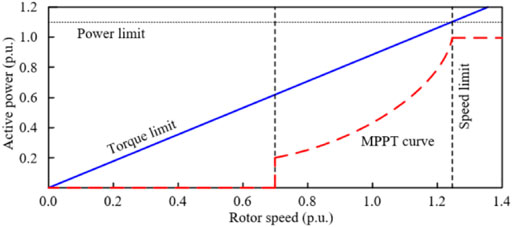
When the wind turbine output power is abnormally excessive or rapidly increased, the rapid change of the torque is inevitable. Especially in severe cases, severer mechanical torsion may damage the wind turbine. In order to protect the mechanical structure of the wind turbine and ensure the safe operation, the output power should meet Kang et al. (2016a)
where Pem is the electromagnetic output power; PTlim is the maximum reference power based on torque limit; Tlim indicates the torque limit of the wind turbine and set to 0.88 p. u. in this paper.
Furthermore, the maximum power is 1.10 p. u., the minimum rotor speed is 0.70 p. u., and the maximum rotor speed is 1.25 p. u. as in Yang et al. (2018) (Figure 2).
Analysis the Inertial Control of a DFIG on the Dynamic System Frequency
When the DFIG implements the inertial control, the relationship between the active power variation (ΔPIC) and the rotor speed of the DFIG can be represented as:
where JDFIG means the moment of inertia of the DFIG.
According to the definition of the inertia constant of the SG, the inertia constant of the DFIG (HDFIG) can be expressed as:
where ωn and SDFIG indicate the rated rotor speed and rated capacity of the DFIG, respectively.
Rearranging Eq. 11 and converting it to a per unit (p.u.) system, the expression of Eq. 11 can be modified as in Eq. 13
where ΔPIC_pu and ωpu are ΔPIC and the rotor speed of the DFIG in p. u., respectively.
By integrating both sides of Eqs 13, 14 is obtained
where ΔEpu is the released kinetic energy of the DFIG in p. u. during the inertia response, ωpu(t1) and ωpu(t0) are the rotor speed of the DFIG at t1 and t0 in p. u., respectively.
As in Miao et al. (2015), since the system frequency in p. u. is the same as ωpu, ωpu in Eq. 14 is replaced by the frequency in p. u., thus, the expression of Eq. 14 can be modified as:
where fpu(t1) and fpu(t0) are the system frequency at t1 and t0 in p. u., respectively.
Therefore, the frequency deviation, Δfpu = fpu(t1)—fpu(t0), is given by Eq. 16:
As shown in Eq. 16, it is evidenced that the DFIG can support the system frequency by inertia response. The large ΔEpu can reduce the system frequency deviation so as to boost the FN.
Torque Limit-Based Inertial Control of a DFIG
After the KE stored in rotor is released to support the system frequency, the rotor speed will deviate from the initial operation state, and even cause the wind turbine stalling. Furthermore, the rotor speed recovery trends to cause a significant SFD due to the reduction on the output power. In order to effectively heighten the FN without a stalling and recover the rotor speed with reduced SFD, the inertial control strategy of the DFIG should be carefully designed.
The following section briefly introduces the characteristics of the conventional TLBIC scheme of (Kang et al., 2016a). Thereafter, the proposed TLBIC scheme is described in detailed in the second part of this section.
Conventional Torque Limit-based Inertial Control Scheme of a DFIG.
To improve the FN without causing the wind turbine stalling, the process of the TLBIC contains two periods: period of supporting the system frequency (A-B-C trajectory) and period of recovering rotor speed of the wind turbine (C-C’-D-A trajectory) (Figure 3A).
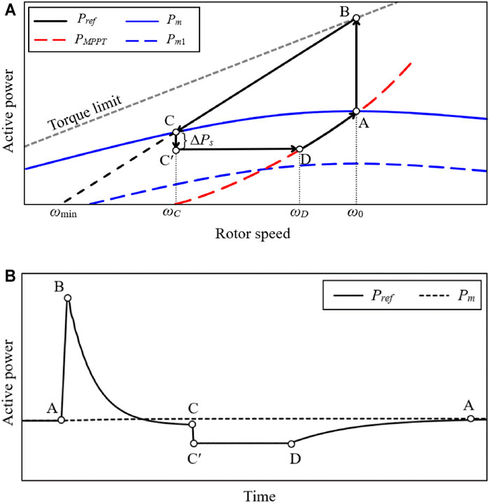
FIGURE 3. Operational features of the conventional TLBIC scheme: (A) Power trajectory in the ωr domain; (B) Active power in the time domain.
Period of Supporting the System Frequency
As shown in A-B-C trajectory of Figure 3A, the DFIG operates at MPPT mode prior to a disturbance, which corresponds to Point A. Upon detecting a disturbance, the power reference of a DFIG instantly increases to Point B (which is the torque limit) along Line A-B so as to boost the FN effectively. To avoid the wind turbine stalling, the reference power Pref decreases along Point B to Point C. During the period of supporting the system frequency, the reference power Pref, is given by:
where ωmin is the minimum rotor speed; ω0 is the rotor speed prior to a disturbance; PMPPT(ωmin) and PMPPT(ω0) are the value of PMPPT at ωmin and ω0, respectively; PTlim(ω0) is the maximum power corresponding to torque limit at ω0.
Since Pref is greater than the input mechanical power Pm, ωr decreases continuously based on the swing equation. Besides, as described in Eq. 17, the power reference Pref is a linear function of ωr, the active power output will decrease along the Line B-C with ωr (see B-C trajectory in Figure 3A). When Pref becomes equal to Pm at Point C, the rotor speed converges to ωC. Accordingly, ωC is higher than the minimum speed limit ωmin, so that this strategy effectively avoids the stalling of the wind turbine.
Period of Recovering Rotor Speed of the Wind Turbine
As in (Kang et al., 2016a), if ωr satisfies the following condition, ωr converges.
where T is the sampling interval of ωr.
At Point C, the active power Pref(ωC) instantly reduces ΔPs to Point Cʹ so as to recover ωr, and keep the value until the MPPT curve is met. At Point D, Pref is switched to PMPPT. Afterwards, ωr returns from Point D to Point A by the action of the MPPT curve. Pref for C-Cʹ-D stage can be expressed as in Eq. 19.
where ΔPs is a constant.
As displayed in Figure 3B, since the condition Eq. 18 is difficult to achieve. Accordingly, this period of ωr convergence remains for a long time and leads to a waste of the KE which is unnecessary. In addition, to accelerate ωr recovery, a large ΔPs is desirable. However, too large ΔPs may result in a severe SFD undoubtedly. Therefore, it is difficult to counterbalance the size of an SFD and the rotor speed recovery duration.
Proposed Torque Limit-based Inertial Control Scheme of a DFIG
To approach the above issues of the conventional TLBIC scheme, a proposed TLBIC scheme is carried out in this study.
The proposed TLBIC scheme aims to 1) improve the FN at a high level with less released kinetic energy and 2) ensure the frequency stabilization with reduced SFD. To this end, Pref is represented as in Eq. 20, as shown in Figure 4B.
where α is the frequency control parameter; t0 is the moment of disturbance occurrence.
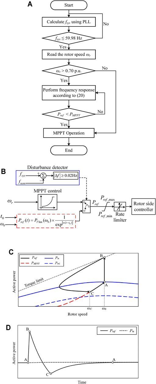
FIGURE 4. Operational features of the proposed TLBIC scheme: (A) Flowchart of the proposed TLBIC scheme; (B) Block diagram of the proposed TLBIC scheme; (C) Power trajectory in the ωr domain; (D) Active power in the time domain.
The flowchart and the power operation features of the proposed TLBIC scheme are presented in Figures 4A,C, respectively. As the conventional TLBIC scheme, the proposed reference power increases instantly from PMPPT(ω0) to PTlim(ω0) at t0 (see A-B trajectory in Figure 4C), so as to provide short-term frequency response. Different from the conventional reference power (which is a function of ωr), the proposed reference power is a function of the time. As time goes on, Pref continues to decrease smoothly until the MPPT curve is met (see B-C trajectory in Figure 4C). At Point C, Pref equals Pm and ωr converges to ωC. Afterwards, Pref of the DFIG switches to PMPPT, and the rotor speed returns to the initial state along the PMPPT curve for optimum power production (see C-A trajectory in Figure 4C).
Compared with the conventional TLBIC scheme, the proposed TLBIC scheme is more manageable, which can control the output active power at the initial period of the frequency response by adjusting α. In addition, the proposed TLBIC scheme starts the restoration of ωr earlier without the period of ωr convergence and avoids the release of unnecessary KE. As shown in Figure 4D; Eq. 20, with the assistance of time-varying power function, Pref decreases smoothly with time and switches to MPPT mode without an active power mutation, which effectively ensures frequency stabilization.
It is quite important to remark that the setting of α in Eq. 20: a small α is instrumental in rapid ωr restoration. However, a small α is not benefit to release the rotating KE and boost the FN; On the contrary, a large α could rise the FN effectively, but it delays ωr recovery and causes a severe SFD. Therefore, the setting of α is critically important. Besides, Pref should be limited by an active power rate limiter and a maximum power limiter.
Modeling of Simulation System
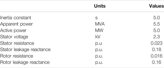
Simulations on various wind power penetrations and wind speed conditions are conducted in EMTP-RV simulator to demonstrate the effectiveness of the proposed TLBIC scheme. As displayed in Figure 5, the model system consists of one aggregated DFIG-based wind farm, six synchronous generators, a 350-MW asynchronous motor, and a 240-MW static load. The main parameters of the DFIG are shown in Table 1.
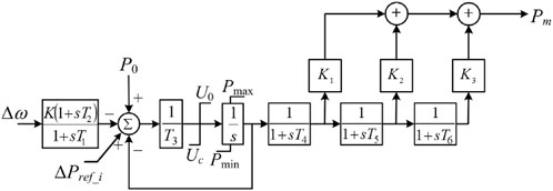
As in (Byerly et al., 1973), all synchronous generators use the IEEEG1 governor and SEXS exciter. The classical configurations of the IEEEG1 model (type B) and SEXS exciter are displayed in Figure 6, 7, respectively. Note that the secondary frequency response is not implemented in this study, thus the frequency will not eventually return to the acceptable range.
Case Studies
In this section, the performances of the proposed scheme under the scenarios by varying the wind power penetration levels of 30 and 40% are verified. Moreover, the average wind speed is set to 8.0 m/s and a stochastic wind speed model is employed in this study. As a disturbance, SG4 which generates 150 MW prior to a disturbance is tripped at 40.0 s.
The following several subsections will compare the performances of the proposed scheme with the conventional scheme and MPPT operation in terms of the system frequency nadir, second frequency drop, starting time of rotor speed recovery, and released kinetic energy, respectively.
The released kinetic energy ΔErel in this paper is defined as:
Case 1: Wind Power Penetration = 30% and Wind Speed = 8 m/s
Figure 8 shows the simulation results for case 1, in which the wind power penetration level is 30% and wind speed condition is 8.0 m/s. In addition, ΔPs for the conventional scheme is set to 0.05 p. u., as suggested in (GB/T19963, 2011), and the KE available from the wind turbine is 1.708 s.
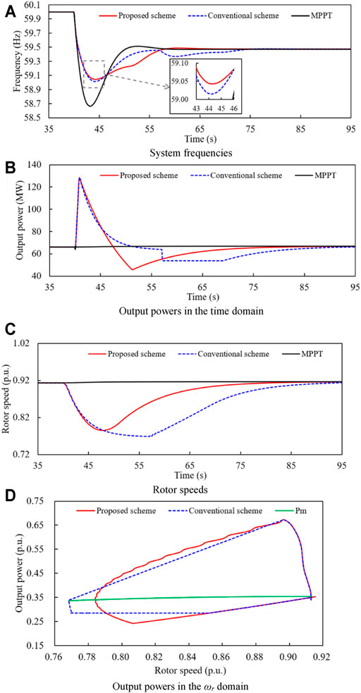
FIGURE 8. Simulation results for case 1. (A) System frequencies. (B) Output powers in the time domain. (C) Rotor speeds. (D) Output powers in the ωr domain.
Since SG4 is offline at t = 40 s, the system active power is out-off-balanced so that the frequency drops. As shown in Figure 8A, the frequency nadirs of the proposed TLBIC scheme, conventional TLBIC scheme, and MPPT control are 59.043, 59.014, and 58.665 Hz, respectively. When the DFIG operates at MPPT mode, it does not participate in system frequency response including inertia response and governor response, thus, its active power output and rotor speed remain unchanged. In addition, compared with the conventional strategy, the FN of the proposed TLBIC strategy is slightly boosted by 0.029 Hz. This is mainly because α is set to 0.1 so that the active power of the proposed TLBIC scheme is larger in the initial period of the inertial response (Figure 8D).
Figure 8C displays the rotor speeds of case 1, ωr in the proposed TLBIC strategy drops faster and decreases to 0.784 p. u. at 47.6 s, and then gradually returns to ω0. Due to the slow rotor speed convergence, ωr in the conventional TLBIC scheme converges to 0.768 p. u. at 57.0 s. Consequently, the proposed TLBIC scheme begins the restoration of the rotor speed earlier than the conventional TLBIC scheme by 9.4 s. Moreover, the KE released from the wind turbine during the inertial response in the proposed TLBIC scheme is 1.085 s, while the released KE in the conventional TLBIC scheme is 1.209 s (Table 2). The reason for this phenomenon is that ωC is more in the proposed TLBIC scheme.
In order to recover ωr, the conventional scheme instantly reduces the output power by 10 MW at 57 s to accelerate the recovery of ωr, which causes a severe SFD of 0.632 Hz (Figures 8A,B). In contrast, the proposed reference power Pref decreases smoothly with time by Eq. 20, which effectively ensures the rapid rotor recovery and frequency stabilization without a fluctuation, as shown in Figure 8A.
Case 2: Wind Power Penetration = 40% and Wind Speed = 8 m/s
Figure 9 shows the simulation results for case 2, in which the wind power penetration level is more than it is in case 1 by 10%.
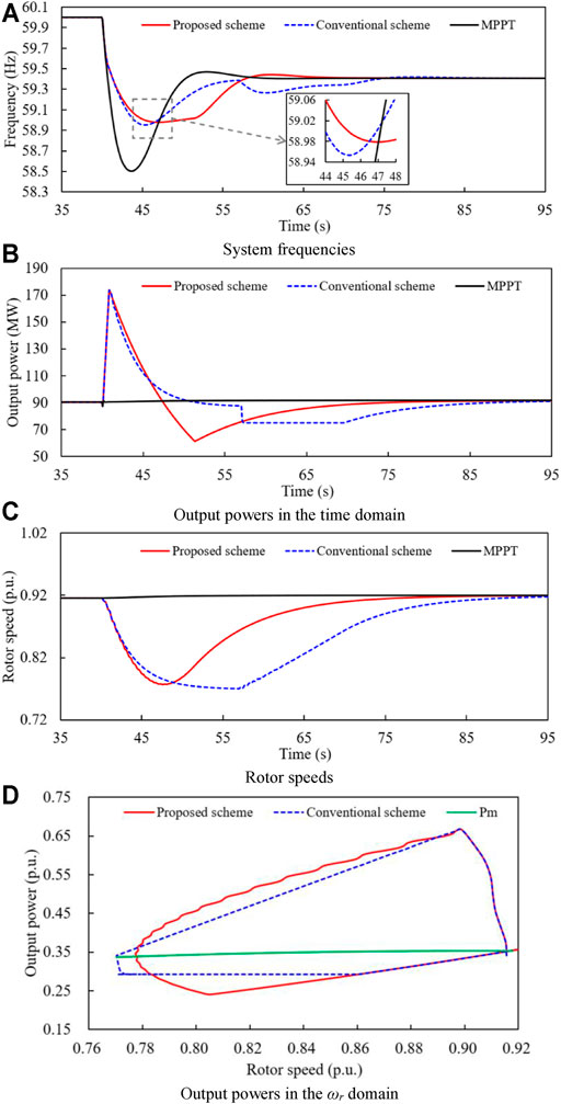
FIGURE 9. Simulation results for case 2. (A) System frequencies. (B) Output powers in the time domain. (C) Rotor speeds. (D) Output powers in the ωr domain.
As illustrated in Figure 9A, the FN of the MPPT operation is 58.501 Hz, which is lower than that of case 1 by 0.164 Hz obviously. This mainly suffers from the higher wind power penetration. Furthermore, the frequency nadirs of the proposed and conventional TLBIC strategy are 58.977 Hz, 58.953 Hz, respectively. Compared with the conventional TLBIC scheme, the FN of the proposed TLBIC scheme is improved by 0.024 Hz due to the setting of α in Eq. 20. In addition, the system frequencies for the proposed and conventional TLBIC strategy reach the steady state at 68.0 and 85.0 s, respectively.
ωr in the proposed and conventional TLBIC scheme start the restoration at 47.6 and 57.0 s, respectively. Moreover, a significant SFD occurs at 60.3 s in the conventional TLBIC scheme while there is no frequency fluctuation in the proposed TLBIC scheme during the restoration of ωr. The size of the SFD for the conventional TLBIC scheme is 0.735 Hz, which is larger than that in case 1 by 0.103 Hz because of a bigger ΔPs.
Table 2 presents the simulation results for case 2, the released KE in the proposed and conventional TLBIC scheme are 1.167 and 1.221 s, respectively. Obviously, the released KE of the proposed TLBIC scheme is less.
Simulation results of the above two cases clearly illustrate that the proposed TLBIC strategy can heighten the FN at a high level with less KE while guaranteeing the fast frequency stabilization under high wind power penetrations.
The above two cases have demonstrated the benefits of the proposed TLBIC strategy under constant wind speed. Whereas, considering the wind velocities are variable in a realistic scenario, the availability of the proposed TLBIC strategy will be investigated on a stochastic wind speed model in the following section.
Case 3: Wind Power Penetration = 30% and Random Wind Speed Condition
The stochastic wind speed model is presented in Figure 10A. As displayed in Figure 10B, the frequency nadirs of the proposed TLBIC scheme, conventional TLBIC scheme, and MPPT control occur at 44.2, 43.7 and 43.2 s and are 59.043, 59.014, and 58.665 Hz, respectively, and the frequency nadirs of three control schemes is all lower than those of case 1 due to the influence of the wind speed drop (Figure 10A). Moreover, the system frequencies for the proposed and conventional TLBIC scheme reach the steady state at 62.0 and 72.0 s, respectively.
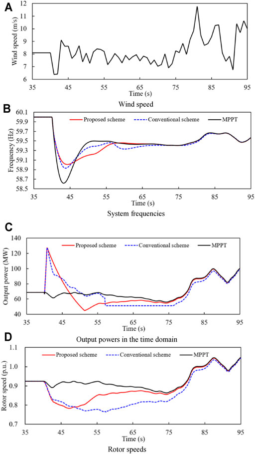
FIGURE 10. Simulation results for case 3. (A) Wind speed. (B) System frequencies. (C) Output powers in the time domain. (D) Rotor speeds.
Since the DFIG output power is closely related to the wind speed, the output power raise at 73 s with the increase of the wind speed (Figures 10A,C). As displayed in Table 2, ωr of the proposed TLBIC scheme starts the recovery at 47.1 s which is earlier than that of the conventional TLBIC scheme by 10.3 s. Furthermore, the released KE during the frequency response in the proposed and conventional TLBIC scheme are 1.203 and 1.350 s, respectively.
Simulation results displayed in case 3 also demonstrate that the advantages and effectiveness of the proposed TLBIC scheme. Even though in a stochastic wind speed, the proposed TLBIC scheme still heightens the FN at a high level with less KE while guaranteeing the rapid frequency stabilization with reduced SFD.
Conclusion
This study suggests an optimized inertial control of a DFIG for heightening the FN at a high level with less KE and guaranteeing the fast frequency stabilization under high wind power penetrations with reduced SFD. To this end, when detecting a disturbance, the active power of the DFIG increases to the torque limit so that enough rotor kinetic energy is released into the power grid, and then the power reference smoothly reduces until the MPPT curve is met. Afterwards, the rotor speed reverts to the initialization along the MPPT curve without a frequency fluctuation.
Simulation results on various wind penetrations and wind velocities significantly demonstrate that the proposed TLBIC scheme shows better performances during the frequency response over the conventional TLBIC scheme: 1) during the period of supporting the system frequency, the proposed TLBIC strategy heightens the FN at a high level with less released KE; 2) during the period of recovering the rotor speed, the proposed TLBIC scheme guarantees the rapid frequency stabilization with reduced SFD effectively. Consequently, the optimized scheme can provide an effective approach for reducing the waste of the KE and balancing the depth of the SFD and the duration of rotor speed restoration.
Data Availability Statement
The raw data supporting the conclusions of this article will be made available by the authors, without undue reservation, to any qualified researcher. Requests to access the datasets should be directed to HW, wanghongmei@ntu.edu.cn.
Author Contributions
YX contributed to the conception and design of the proposed strategy. All authors wrote and edited the manuscript.
Funding
This work was supported by the Natural Science Foundation of the Jiangsu Higher Education Institutions of China (20KJB470026).
Conflict of Interest
The authors declare that the research was conducted in the absence of any commercial or financial relationships that could be construed as a potential conflict of interest.
Publisher’s Note
All claims expressed in this article are solely those of the authors and do not necessarily represent those of their affiliated organizations, or those of the publisher, the editors and the reviewers. Any product that may be evaluated in this article, or claim that may be made by its manufacturer, is not guaranteed or endorsed by the publisher.
References
Bao, W., Ding, L., and Liu, Z. (2020). Analytically derived fixed termination time for stepwise inertial control of wind turbines—Part I: Analytical derivation. Inter. J. Elect. Power Energ. Sys 121, 1–10. doi:10.1016/j.ijepes.2020.106120
Boukhezzar, B., and Siguerdidjane, H. Nonlinear control of a variable speed wind turbine using a two-mass model. IEEE Trans. Energ. Convers. 26 (1), 149–161. Mar. 2011.
Byerly, R. T., Aanstad, O., and Berry, D. H. (1973). Dynamic models for steam and hydro turbines in power system studies. IEEE Trans. Power App. Syst. 92 (6), 1904–1915.
Fernandez, L. M., Garcia, C. A., and Jurado, F. (2008). Comparative study on the performance of control systems for doubly fed induction generator (DFIG) wind turbines operating with power regulation. Energy 33 (9), 1438–1452. doi:10.1016/j.energy.2008.05.006
Hafiz, F., and Abdennour, A. (2015). Optimal use of kinetic energy for the inertial support from variable speed wind turbines. Renew. Energ. 80, 629–643. doi:10.1016/j.renene.2015.02.051
Hu, Y.-L., and Wu, Y.-K. (2019). Approximation to frequency control capability of a DFIG-based wind farm using a simple linear gain droop control. IEEE Trans. Ind. Applicat. 55 (3), 2300–2309. doi:10.1109/tia.2018.2886993
Kang, M., Kim, K., and Muljadi, E. (2016). Frequency control support of a doubly-fed induction generator based on the torque limit. IEEE Trans. Power Syst. 31 (6), 4574–4583. doi:10.1109/tpwrs.2015.2514240
Kang, M., Muljadi, E., Hur, K., and Kang, Y. C. (2016). Stable adaptive inertial control of a doubly-fed induction generator. IEEE Trans. Smart Grid 7 (6), 2971–2979.
Kheshti, M., Ding, L., Nayeripour, M., Wang, X., and Terzijia, V. (2019). Active power support of wind turbines for grid frequency events using a reliable power reference scheme. Renew. Energ. 139, 1421–1454. doi:10.1016/j.renene.2019.03.016
Lao, H. (2021). Innovated inertia control of DFIG with dynamic rotor speed recovery. CSEE J. Power Energ. Syst.
Lee, J., Jang, G., Muljadi, E., Blaabjerg, F., Chen, Z., and Cheol Kang, Y. (2016). Stable short-term frequency support using adaptive gains for a DFIG-based wind power plant. IEEE Trans. Energ. Convers. 31 (3), 1068–1079. doi:10.1109/tec.2016.2532366
Li, Y., Xu, Z., and Wong, K. P. (2017). Advanced control strategies of PMSG-based wind turbines for system inertia support. IEEE Trans. Power Syst. 32 (4), 3027–3037. doi:10.1109/tpwrs.2016.2616171
Miao, L., Wen, J., Xie, H., Yue, C., and Lee, W.-J. (2015). Coordinated Control Strategy of Wind Turbine Generator and Energy Storage Equipment for Frequency Support. IEEE Trans. Ind. Applicat. 51 (4), 2732–2742. doi:10.1109/tia.2015.2394435
Morren, J., Pierik, J., and de Haan, S. W. H. (2006). Inertial response of variable speed wind turbines. Electric Power Syst. Res. 76 (11), 980–987. doi:10.1016/j.epsr.2005.12.002
Peng, X., Yao, W., Yan, C., Wen, J., and Cheng, S. (2020). Two-Stage Variable Proportion Coefficient Based Frequency Support of Grid-Connected DFIG-WTs. IEEE Trans. Power Syst. 35 (2), 962–974. doi:10.1109/tpwrs.2019.2943520
Ullah, N. R., Thiringer, T., and Karlsson, D. (2008). Temporary Primary Frequency Control Support by Variable Speed Wind Turbines- Potential and Applications. IEEE Trans. Power Syst. 23 (2), 601–612. doi:10.1109/tpwrs.2008.920076
Van de Vyver, J., De Kooning, J. D. M., Meersman, B., Vandevelde, L., and Vandoorn, T. L. (2016). Droop control as an alternative inertial response strategy for the synthetic inertia on wind turbines. IEEE Trans. Power Syst. 31 (2), 1129–1138. doi:10.1109/tpwrs.2015.2417758
Wang, S., and Tomsovic, K. (2018). A novel active power control framework for wind turbine generators to improve frequency response. IEEE Trans. Power Syst. 33 (6), 6579–6589. doi:10.1109/tpwrs.2018.2829748
Wu, Y.-K., Yang, W. H., and Hu, Y. L. Frequency regulation at a wind farm using a timing–varying inertia and droop controls. IEEE Trans. Ind. Appl. 55 (1), 213–2224. Jan./Feb. 2019.
Wu, Z., Gao, D. W., Zhang, H., Yan, S., and Wang, X. (2017). Coordinated control strategy of battery energy storage system and PMSG-WTG to enhance system frequency regulation capability. IEEE Trans. Sustain. Energ. 8 (3), 1330–1343. doi:10.1109/tste.2017.2679716
Xiong, L., Liu, L., Liu, X., and Liu, Y. (2021). Frequency Trajectory Planning Based Strategy for Improving Frequency Stability of Droop-Controlled Inverter Based Standalone Power Systems. IEEE J. Emerg. Sel. Top. Circuits Syst. 11 (1), 176–187. doi:10.1109/jetcas.2021.3052006
Xiong, L., Liu, X., Liu, Y., and Zhuo, F. (2020). Modeling and Stability Issues of Voltage-Source Converter Dominated Power Systems: a review. CSEE J. Power Energ. Syst. (Early Access), 1–18.
Xiong, L., Liu, X., Zhang, D., and Liu, Y. (2021). Rapid Power Compensation-Based Frequency Response Strategy for Low-Inertia Power Systems. IEEE J. Emerg. Sel. Top. Power Electron. 9 (4), 4500–4513. doi:10.1109/jestpe.2020.3032063
Xiong, Y., Yao, W., and Fen, J. (2021). Two-level combined control scheme of VSC-HVDC integrated off shore wind farms for onshore system frequency support. IEEE Trans. Power Syst. 36 (1), 781–792.
Xu, G., Liu, F., Hu, J., and Bi, T. (2018). Coordination of wind turbines and synchronous generators for system frequency control. Renew. Energ. 129, 225–236. doi:10.1016/j.renene.2018.05.104
Xu, G., and Xu, L. (2017). Improved use of WT kinetic energy for system frequency support. IET Renew. Power Generation 11 (8), 1094–1100. doi:10.1049/iet-rpg.2016.0183
Yang, D., Jin, Z., Zheng, T., Jin, E., Zhang, X., and Hua, L. (2021). Frequency Control Scheme with Dynamic Droop Characteristics of a DFIG for Mitigating the Frequency Fluctuations. Int. Trans. Ele ctr. Energ. Syst. 33 (11), 1–11.
Yang, D., Jin, Z., Zheng, T., and Jin, E. (2022). An adaptive droop control strategy with smooth rotor speed recovery capability for type III wind turbine generators. Int. J. Electr. Power Energ. Syst. 135, 107532. doi:10.1016/j.ijepes.2021.107532
Keywords: frequency stability, torque limit-based inertial control, frequency nadir, second frequency drop, rotor speed recovery
Citation: Xu Y and Wang H (2021) Torque Limit-Based Inertial Control of a DFIG for Rapid Frequency Stabilization. Front. Energy Res. 9:788989. doi: 10.3389/fenrg.2021.788989
Received: 04 October 2021; Accepted: 21 October 2021;
Published: 22 November 2021.
Edited by:
Liansong Xiong, Nanjing Institute of Technology (NJIT), ChinaReviewed by:
Jun Cong Ge, Jeonbuk National University, South KoreaHuimin Wang, University of Electronic Science and Technology of China, China
Zhaoyang Jin, Shandong University, China
Copyright © 2021 Xu and Wang. This is an open-access article distributed under the terms of the Creative Commons Attribution License (CC BY). The use, distribution or reproduction in other forums is permitted, provided the original author(s) and the copyright owner(s) are credited and that the original publication in this journal is cited, in accordance with accepted academic practice. No use, distribution or reproduction is permitted which does not comply with these terms.
*Correspondence: Hongmei Wang, d2FuZ2hvbmdtZWlAbnR1LmVkdS5jbg==
 Yien Xu
 Hongmei Wang*