 Peng Chen
 Zijie Wu
 Dekui Zhan
 Shaoxiong Xia
 Xinhai Zhao
94% of researchers rate our articles as excellent or good
Learn more about the work of our research integrity team to safeguard the quality of each article we publish.
Find out more
ORIGINAL RESEARCH article
Front. Energy Res., 24 February 2022
Sec. Nuclear Energy
Volume 9 - 2021 | https://doi.org/10.3389/fenrg.2021.785513
This article is part of the Research TopicExperimental and Analytical Investigations on Nuclear Reactor Safety, Severe Accident Phenomena and Severe Accident Mitigation of Nuclear Power PlantsView all 20 articles
Due to large uncertainty, the effectiveness of in-vessel retention (IVR) with external reactor vessel cooling (ERVC) for high-power reactors cannot be fully demonstrated during the transient process. To optimize the current IVR-ERVC strategy, the concept of IVR-ERVC with in-vessel injection (IVI) is studied. Two feasible IVI designs are proposed: 1) using the passive IVR water tank to implement simultaneous water injection in-vessel and ex-vessel and 2) using the passive severe accident dedicated in-vessel injection tanks (SADITs) to implement water injection in-vessel. The research on the feasibility and effectiveness of IVI is performed, and the corresponding negative effects are analyzed. The calculation results by using MIDAC show that the two proposed IVI concepts can greatly delay the accident progression in the core and reduce the decay heat peak of the molten pool in the lower head, thereby improving the effectiveness of the current IVR-ERVC strategy. And the negative effects are within acceptable ranges.
After the Fukushima nuclear accident, nuclear regulatory authorities of various countries put forward more stringent requirements for nuclear safety. The Chinese National Nuclear Safety Administration (NNSA) requires new nuclear reactors to achieve “practical elimination of large radioactive release” (Ma et al., 2016). As the last safety barrier, the integrity of the containment is essential to prevent large-scale leakage of radioactive materials. To avoid the occurrence of molen corium concrete interaction (MCCI) and direct containment heating (DCH) which threatens the integrity of containment, the in-vessel retention (IVR) with external reactor vessel cooling (ERVC) strategy is adopted in Chinese HPR1000 (Xing et al., 2016).
Due to high reliability and low construction difficulty, the concept of IVR-ERVC is widely employed in the GEN-III and GEN-II+ pressurized water reactors (PWRs), including AP600/1000 (Zhang et al., 2010), APR1400 (Oh and Kim, 2005), VVER1000/320 (Sangiorgi and Ezzidi, 2015), and CAP1400 (Shi et al., 2019). The key principle of the IVR-ERVC strategy lies in that the external cooling water is quickly injected into the reactor pit through active or passive means after severe accidents, forming a natural circulation in the annular flow channel. The heat generated by corium is taken away by means of external cooling of the reactor pressure vessel (RPV), and other safety functions are simultaneously implemented (such as primary circuit pressure relief) to maintain the integrity of the pressure vessel. The successful implementation of the IVR-ERVC strategy needs to meet the following criteria (Fichot et al., 2018):
1) The local heat flux density on the inner wall surface of the lower head is less than the critical heat flux (CHF) profiles.
2) The minimum vessel thickness reached after ablation by corium can withstand the maximum load that is applied to the vessel during the transient process.
For low-power reactors such as VVER440 and AP600, the effectiveness of the IVR-ERVC strategy has enough margin due to low decay heat of corium (Kymäläinen et al., 1997; Theofanous et al., 1997). But for reactors with higher power, such as AP1000 and APR1400, the effectiveness of the IVR-ERVC strategy cannot be fully guaranteed (Fichot et al., 2018). It is firstly due to the large uncertainty of accident progression in the core. In some transient processes, the focusing effect is significant due to a thin metallic layer, in which the local heat flux density of the lower head may be greater than the CHF profiles (Carénini and Fichot, 2016). It is secondly due to the uncertainty of physical models used in integral codes for severe accident analysis. The calculation results of integral codes (including ASTEC, ATHLET-CD, and MAAP_EDF) for the minimum vessel thickness show a large variability (about ±80%) (Carénini et al., 2019). The significant discrepancy leads to a great uncertainty in the reasonable assessment of IVR-ERVC effectiveness.
Although there is uncertainty in the analysis of the IVR-ERVC strategy for high-power reactors, it is certain that the decay heat of the core decreases with time after shutdown. It can be deduced that as long as the core melt relocates to the lower head late enough, the maximum decay heat in the corium pool can be greatly reduced, thereby increasing the successful possibility of the IVR-ERVC strategy.
One of the most effective ways to delay or even terminate the accident process in the reactor is to perform the injection of water into the vessel. In severe accidents, more than 80% of core damage can be mitigated by implementing additional core cooling (Nuclear Regulatory Commission, 1989). But the in-vessel injection (IVI) is always accompanied by negative risks. And the effectiveness and negative effects of IVI are highly correlated with the time of water injection (Jun et al., 2011). The key negative effects include the following (Dorsselaere et al., 2006):
1) Hydrogen risk: After the injected cooling water comes into contact with the exposed fuel bundle or debris bed at high temperature, a large amount of steam will be generated instantly, which enhances the oxidation of zirconium cladding. It is found from the CORA13 experiment that 48% of the total hydrogen was generated during the flooding phase (Hagen et al., 1993). The oxidation heat accelerates the core damage, and the massive hydrogen generated increases the risk of hydrogen explosion inside the containment.
2) Primary System (PS) overpressure: The overpressure risk in the primary system induced by massive steam generated may result in yield failure of the lower head and creep failure of the steam generator heat transfer tubes, which penalizes the integrity of RPV and increases the leakage risk of fission products to the secondary circuit.
3) Fission Product (FP) release: A large number of cracks are produced between or within the grains in the high-temperature fuel pellets during the reflooding phase, and the injected coolant crushes the embrittled fuel rods, causing the increase in the amount of fission products released from the core. The LOFT-LP-FP2 experiment data show that 80% of the initial storage of fission products was released during the reflooding process (Coryell and April, 1994). The PBF SFD-ST experiment also presents that most of the fission products were released during and after water injection (Wright, 1994).
To delay the accident progression in the core and reduce the decay heat of the molten pool in the lower head, the research on the feasibility and effectiveness of in-vessel injection is performed in this paper, and the corresponding negative effects are analyzed. The concept of IVR-ERVC with IVI is studied to optimize the current IVR-ERVC strategy, thereby improving the IVR effectiveness for high-power reactors and enhancing their ability to deal with severe accidents.
For typical advanced Chinese 1000MWe PWRs using the IVR-ERVC strategy, the severe accident management strategies include the following: 1) Once the temperature of the core outlet exceeds 650°C, the severe accident dedicated valve is opened to prevent the occurrence of high-pressure melt ejection (HPME). 2) Then, the passive IVR tank is activated by the operator, in which water is injected into the pit through a large flow line to quickly flood the lower head of the pressure vessel. 3) When the water in the IVR tank is nearly depleted, the active water injection from the in-containment refueling water storage tank (IRWST) into the pit with small flow lines is carried out, to compensate for the loss of evaporated water and realize the long-term cooling.
The research on the concept of IVR-ERVC with IVI is performed to optimize the current IVR-ERVC strategy. Considering not challenging the current severe accident mitigation strategies and not significantly increasing the pressure boundary of the primary circuit, the following two IVI strategies are proposed:
1) Using the passive IVR water tank to implement simultaneous water injection in-vessel and ex-vessel
2) Using passive severe accident dedicated in-vessel injection tanks (SADITs) to implement water injection in-vessel
To verify the effectiveness of IVI strategies and evaluate negative effects, MIDAC (Module In-vessel Degraded severe accident Analysis Code) (Wang et al., 2014a) is used to calculate and analyze the impact of IVI on core degradation, corium relocation, and heat transfer in the molten pool under severe accidents. MIDAC is developed by Xi’an Jiaotong University, which can analyze the processes of in-vessel severe accident thoroughly (Wang et al., 2014b). Through the verification of FROMA, QUENCH06&16, TMI-2, and other experiments (Wu et al., 2021; Wang et al., 2019), MIDAC proved to be able to provide the relevant analyzing result of each course accurately.
The accident scenario of large break-loss of coolant accident (LB-LOCA) is the fastest, and the consequences are the worst. Therefore, LB-LOCA is selected as the bounding case for other accident sequences to perform the effectiveness analysis. The main assumptions include the following:
1) Occurrence of double-ended guillotine break at a cold leg in loop 1 at 200 s
2) Failure of medium head safety injection (MHSI), low head safety injection, and containment spray system
3) Accumulators (ACCs), passive IVR, and active injection of the IRWST available
As for the boundary conditions, the calculation object includes all the components inside the containment of HPR1000. The boundary conditions include the boundaries of RPV, the primary circuit, and the containment. In the scenario of IVR, the cavity is flooded with water. The code calculates the boiling heat flux at the RPV outer surface boundary. For the rest of the primary circuit, according to HPR1000 reactor design, a layer of rock wool insulation is implemented in the model, providing an extra thermal resistance. For the containment wall, an adiabatic boundary is used for the conservative consideration of containment pressure and temperature.
The schematic of the first IVI strategy with a passive IVR tank is shown in Figure 1, in which the red line shows the additional pipelines and equipment. When the primary system is fully depressurized under severe accidents, the water from the passive IVR tank is simultaneously injected into the cold leg in loop 1 and the reactor pit by gravity.
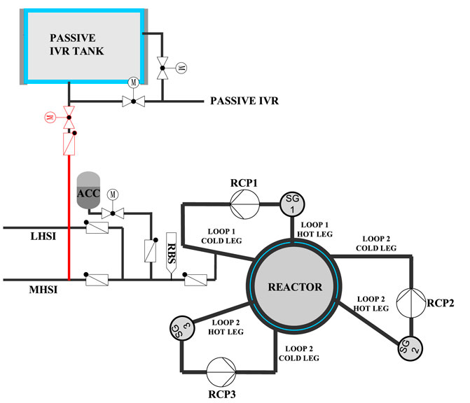
FIGURE 1. Schematic of the IVI strategy with a passive IVR tank.
The effectiveness and negative effects of IVI strongly depend on the implementation moment and the amount of water injection in-vessel. In case of a small part of core exposed and the fuel bundle is at low temperature, the core is quickly reflooded after in-vessel injection which can greatly prevent the core degradation from further deterioration. When most part of the core area has been exposed, the temperature of fuel rods rises rapidly due to lack of effective cooling. After the implementation of in-vessel injection, the large amount of steam generated enhances the oxidation of cladding, resulting in a further increase of temperature in fuel rods and aggravating the core damage process. When performing the in-vessel injection in the late phase of core degradation, a solidified crust is formed on the periphery of molten pool in the core region or lower head, which hinders the cooling of the central area in the molten pool, causing the melt to present uncoolability.
In addition, due to the limited amount of water in the passive IVR tank, the implementation of IVI will inevitably affect the volume of injected water in the pit. In order to reduce the impact on ex-vessel injection, and also to select the most effective measures for water injection in the vessel, the sensitivity analysis on the IVI implementation moment and water injection flow is performed.
To perform the sensitivity analysis on the implementation moment of IVI, 20, 40, 60, 80, 100, and 120 min after the core outlet temperature exceeds 650°C are considered in the calculation by MIDAC. Namely, if the core outlet temperature exceeds 650°C at 0 s, the water injection in the reactor shall be carried out at 1200 s/2400 s/3600 s/4800 s/6000 s/7200 s, respectively, for different sensitivity analysis cases.
Figures 2–4, respectively, show the distribution of core node temperature at different time for the various selected implementation moments of IVI, from which the core damage fraction can be clearly observed. The core node temperature in MIDAC represents the average temperature of core components such as fuel, cladding, and control rods in each computational cell. It can be found that the implementation moment of IVI is earlier, and the core damage fraction at 5 and 10 h after LB-LOCA is lower, which indicates that the water injection in-vessel in the early core degradation phase can reduce the melt mass relocated into the lower head and then decrease the decay heat of the molten pool. It can be explained by the fact that the earlier the IVI is implemented, the longer the water injection in-vessel is maintained before the IVR tank is depleted, which can provide more long-term cooling in the core.
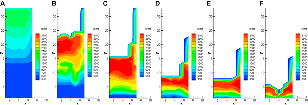
FIGURE 2. Temperature distribution at different implementation moments of IVI: (A) 20 min; (B) 40 min; (C) 60 min; (D) 80 min; (E) 100 min; (F) 120 min.
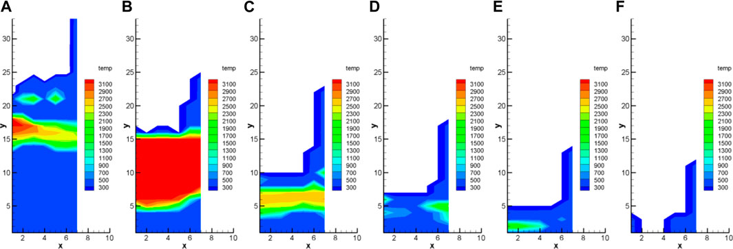
FIGURE 3. Temperature distribution at 5 h for different implementation moments of IVI: (A) 20 min; (B) 40 min; (C) 60 min; (D) 80 min; (E) 100 min; (F) 120 min.
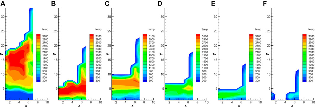
FIGURE 4. Temperature distribution at 10 h for different implementation moments of IVI: (A) 20 min; (B) 40 min; (C) 60 min; (D) 80 min; (E) 100 min; (F) 120 min.
Without additional water supply, the core is in a pool boiling state before being dried out. The purpose of water injection in the reactor is to compensate for the loss of coolant due to evaporation. The water injection flow rate is actually determined by the pipeline diameter. Through comparing the evaporation rate of the coolant, 40, 60, and 80 mm of IVI pipeline diameter are selected to perform sensitivity analysis.
Figures 5–7 present the temperature distribution at different time with 40, 60, and 80 mm of IVI pipeline diameter, respectively. It can be found that the water injection with 20 mm of pipe diameter cannot significantly alleviate the damage process in the core due to the small injection flow. Within 5 h after the accident, the mitigation effect for core damage with 80 mm pipe diameter is better than that of 60 mm. But the core damage fraction with 80 mm pipe diameter at 10 h is significantly greater than that of 60 mm, which is due to the fact that the IVR water tank is depleted earlier in the case of 80 mm pipe diameter, resulting in a shorter period to maintain the water injection in-vessel. After the IVR tank is depleted, the water injection in the core is ceased, causing the core damage process to be restarted.
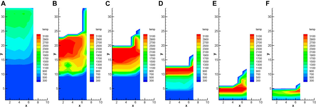
FIGURE 5. Temperature distribution at different time with 40 mm of IVI pipeline diameter: (A) 20 min; (B) 40 min; (C) 60 min; (D) 3 h; (E) 5 h; (F) 10 h.
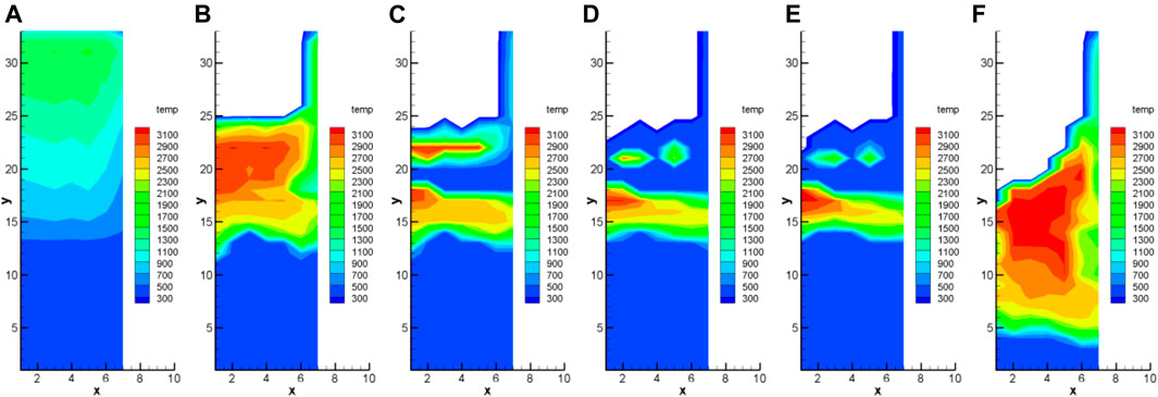
FIGURE 6. Temperature distribution at different time with 60 mm of IVI pipeline diameter: (A) 20 min; (B) 40 min; (C) 60 min; (D) 3 h; (E) 5 h; (F) 10 h.
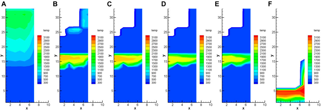
FIGURE 7. Temperature distribution at different time with 80 mm of IVI pipeline diameter: (A) 20 min; (B) 40 min; (C) 60 min; (D) 3 h; (E) 5 h; (F) 10 h.
According to the sensitivity analysis on the IVI implementation moment and injection pipeline diameter, it can be concluded that the best IVI strategy is to implement the water injection in-vessel at 20 min after the core outlet temperature exceeds 650°C and with 60 mm of injection pipeline diameter. However, the calculation results of this strategy show that the amount of water injected into the reactor pit within half an hour after the implementation of passive IVR is less than the design value. In order to meet this requirement, the implementation of IVI at 40 min after the core outlet temperature exceeds 650°C and with 60 mm of pipeline diameter is selected as the first IVI strategy with a passive IVR tank (referred to as the 40 min 60 mm strategy).
Nevertheless, Figures 2–4 show that the mitigation effect for core damage with the 20 min 60 mm strategy is much better than that of 40 min 60 mm. In order to satisfy the requirement on the quantity of water injection ex-vessel, it is necessary to increase the initial water capacity in the passive IVR tank under the premise of available space. Based on the sensitivity analysis on the initial water level in the IVR tank, the following optimized strategy is proposed.
Optimization strategy 1.1: 1) Increase the initial water level in the IVR tank to 8.01 m. 2) Implement the simultaneous water injection in-vessel and ex-vessel at 20 min after the core outlet temperature exceeds 650°C and with 60 mm of IVI pipeline diameter. 3) When the water level in the IVR tank is nearly depleted, carry out the active water injection from the IRWST into the pit.
After the passive IVR tank is depleted, the core meltdown process is restarted. To delay the time for the IVR tank to be empty, the initial water capacity in the IVR tank can be continued to be increased. However, the containment space is limited. The IVR tank with too large volume will inevitably affect the space availability of other equipment. The redistribution of equipment in the containment will bring too much work. Therefore, the method of continuously increasing the water volume in the IVR tank is not operable in the engineering practice. Instead, it may be considered to carry out the active pit injection system in advance, to increase the water injection volume in-vessel while reducing the water injection ex-vessel from the IVR tank. Through sensitivity analysis, the second selected IVI optimization strategy with a passive IVR tank is presented.
Optimization strategy 1.2: 1) Increase the initial water level in the IVR tank to 8.01 m. 2) Implement the simultaneous water injection in-vessel and ex-vessel at 20 min after the core outlet temperature exceeds 650°C and with 60 mm of IVI pipeline diameter. 3) When the water level in the IVR tank is less than 2 m, carry out the active water injection from the IRWST into the pit and cease the passive water injection into the pit.
The water capacity of the IVR tank is much smaller than that in the IRWST. Therefore, for further optimization of the IVI strategy, it can be considered to continue the in-vessel injection through the IRWST after the passive IVR tank is depleted (referred to as optimization strategy 1.3). The detailed description is as follows.
Optimization strategy 1.3: 1) Increase the initial water level in the IVR tank to 8.01 m. 2) Implement the simultaneous water injection in-vessel and ex-vessel at 20 min after the core outlet temperature exceeds 650°C and with 60 mm of IVI pipeline diameter. 3) When the water level in the IVR tank is nearly depleted, inject water into the IVR tank through the active pipeline from the IRWST, to continue the simultaneous water injection in-vessel and ex-vessel.
In the process of water injection in-vessel, a large amount of steam will be generated after the contact between the coolant and fuel rods at high temperature, which may cause the pressure in the primary circuit to increase significantly. The passive IVR water tank injects water into the reactor through gravity. In this condition, the in-vessel injection by a passive IVR tank may be ceased due to the overpressure in the primary circuit. In order to ensure the successful implementation of water injection in-vessel, the concept of passive SADITs is proposed (referred to as optimization strategy 2).
The schematic of the IVI strategy with passive SADITs is shown in Figure 8, in which the passive IVR tank is only used for ex-vessel injection. The key equipment added contains three trains of passive dedicated in-vessel injection tanks as well as related valves and pipelines, the principle of which is consistent with that of ACCs, including a compressed gas zone and a water zone. The process of water injection into the reactor is divided into two stages:
1) When the primary circuit pressure is lower than the setting value, the ACCs are triggered, in which the water is quickly injected into the pressure vessel through a large flow pipeline.
2) When the primary circuit pressure is lower than 0.5 MPa and the core outlet temperature exceeds 650°C, the passive SADITs are activated by the operator. The in-vessel injection is carried out with a small pipeline (60 mm diameter). Each train of SADIT injects 60 m3 of water into the pressure vessel. The initial pressure of compressed gas in the SADIT is 1 MPa.
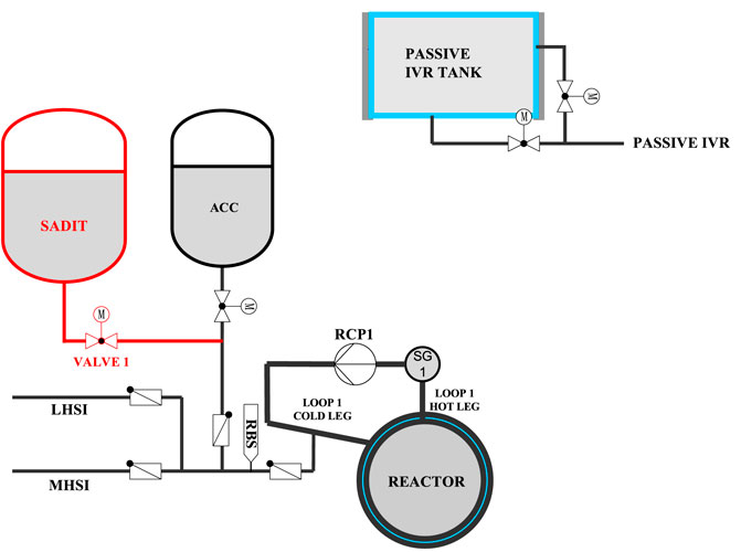
FIGURE 8. Schematic of the IVI strategy with the passive SADIT.
In this section, the effectiveness assessment for various IVI strategies mentioned above is performed compared with the design without IVI.
The key events in the core damage progression after LB-LOCA for various IVI strategies are shown in Table 1. Compared with the design without the water injection in-vessel, the various IVI strategies can significantly delay the moment at which the core is completely exposed and the corium relocates into the lower head. Figure 9 presents the core collapsed water level. It could be found that optimization strategy 2 implements earliest the water injection in-vessel, in which most of the core area is not exposed during the water injection process. In optimization strategy 1.3, the IRWST maintains the in-vessel injection for more than 72 h, which ensures that the core is always submerged and prevents the core melt from relocating into the lower head. Compared with the design without IVI, the 40 min 60 mm strategy, optimization strategy 1.1, optimization strategy 1.2, and optimization strategy 2 delay the relocation moment of corium to the lower head for 7.15, 9.25, 10.77, and 4.17 h, respectively. And the following can be summarized:
1) Optimization strategy 1.1 can maintain the core in the submerged state for at least 6 h.
2) Optimization strategy 1.2 can maintain the core in the submerged state for at least 10 h.
3) Optimization strategy 1.3 can maintain the core in the submerged state for at least 72 h.
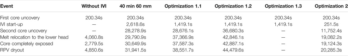
TABLE 1. Key events in the core damage progression.
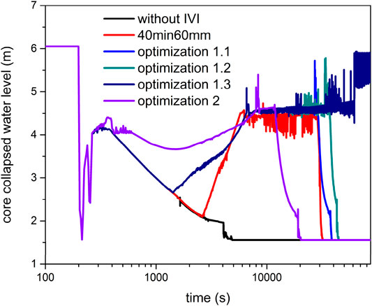
FIGURE 9. Core collapsed water level.
Figure 10 shows total decay power in the lower plenum debris, from which it could be found the moment of corium relocated into the lower head and there is the maximum decay power in the molten pool. The maximum decay heat and the composition in the molten pool are presented in Table 2. Since the decay heat power decreases with time after shutdown, the delay on the moment of corium relocation can greatly reduce the maximum decay heat in the molten pool. Compared with the design without the water injection in-vessel, the peaks of decay heat for the 40 min 60 mm strategy, optimization strategy 1.1, optimization strategy 1.2, and optimization strategy 2 are decreased by 29.8, 30.7, 33.2, and 19.7%, respectively.
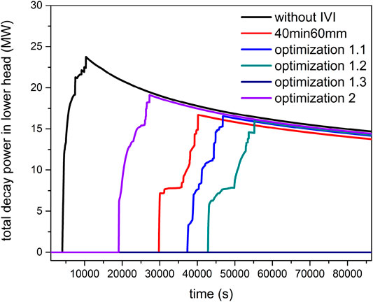
FIGURE 10. Total decay power in the lower plenum debris.
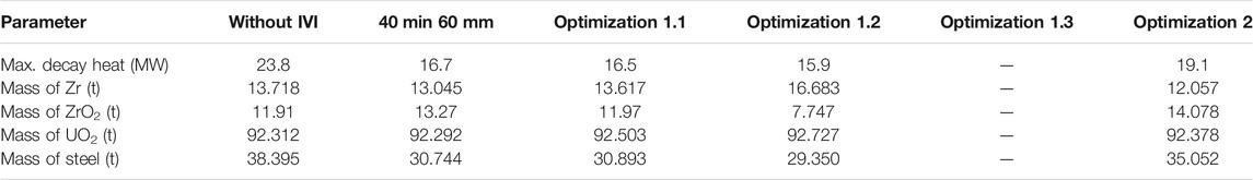
TABLE 2. Maximum decay heat and composition in the molten pool.
To assess the effectiveness of various IVI strategies, the local heat flux along the lower head is compared with CHF profiles in the external surface of lower head, in which the CHF profiles are determined by the REVECT (REactor Vessel External Cooling Test) facility (Zhan et al., 2020). Figure 11 presents the comparison between the local heat flux and the CHF profiles. Due to the focusing effect in the molten pool, the local heat flux in the metallic layer is maximum. Since the decay heat in the molten pool is reduced by delaying the relocation of corium in the lower head in various IVI strategies, the margin for the effectiveness of IVR can be greatly increased, as shown in Table 3. It can be concluded that the implementation of early in-vessel injection after severe accidents has a significant positive effect on delaying the accident progression in the core and increasing the margin of IVR effectiveness.
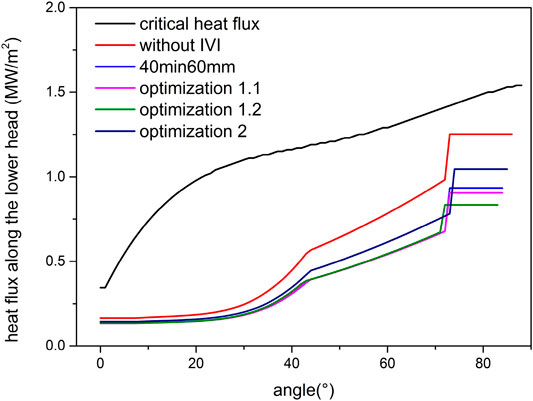
FIGURE 11. Heat flux along the lower head compared with the CHF.
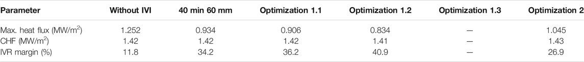
TABLE 3. IVR margin for various IVI strategies.
The key risks of water injection in-vessel are concentrated in 1) hydrogen explosion, 2) PS and containment overpressure, 3) FP release, and 4) steam explosion in-vessel. Severe experiments have been carried out to analyze the mechanism of steam explosion, including KROTOS (Huhtiniemi and Magallon, 2001) and FARO (Magallon et al., 1999). It is found that, without external triggering, the spontaneous occurrence of steam explosion in-vessel is very hard (Fletcher, 1994). The SERG (Steam Explosion Review Group) project points out that the conditions for triggering the in-vessel explosion are very rigorous, and the possibility is concluded to be unlikely (Basu and Ginsberg, 1996). And the SERENA (Steam Explosion Resolution for Nuclear Application) program demonstrates the safety margin for in-vessel steam explosion could be considered sufficient (Magallon and Bang, 2007). Therefore, the negative effect for steam explosion in-vessel is not considered in this paper.
Figure 12 presents the integrated mass of H2 generated in the core and lower plenum. Before the implementation of in-vessel injection, the hydrogen mass in 40 min 60 mm, optimization 1.1, optimization 1.2, and optimization 1.3 is consistent with the design without IVI. After the first core uncovery, the temperature of the fuel rods rises rapidly and the cladding is oxidized to generate a large amount of hydrogen.
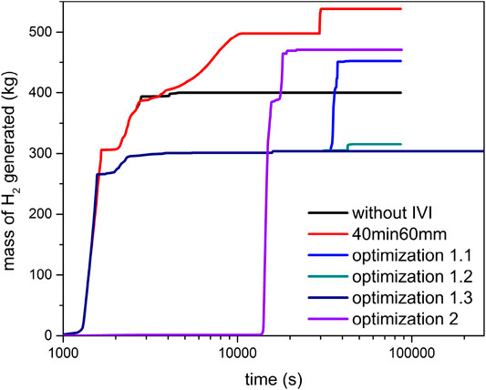
FIGURE 12. Integrated mass of H2 generated in the core and lower plenum.
As shown in Figure 2, most of the core temperature has exceeded 1000 K when the IVI is carried out in the 40 min 60 mm strategy. Once the cladding temperature exceeds 1000 K, the zirconium alloy begins to undergo intense oxidation. After the water injection in-vessel is implemented, the generated steam greatly increases the oxidation rate, thereby significantly increasing the hydrogen production in the core.
The water injection in-vessel in optimization strategies 1.1–1.3 is carried out earlier, at which about 1/3 of the core area has not been exposed. During the water injection process, this part of core is not oxidized then reducing the mass of hydrogen generated compared with the strategy without IVI. Figure 13 presents the temperature distribution of cladding for optimization strategy 2. It can be found the temperature of the entire core cladding is lower than 1500 K during the water injection stage, which penalizes the cladding oxidation, resulting in hydrogen production close to zero. After the water injection in-vessel is ceased, the core degradation is restarted, causing an increase in hydrogen production. Compared with the design without IVI, optimization strategy 2 can significantly reduce the amount of hydrogen produced within 3.6 h after severe accidents, providing valuable response time for external emergency measures to be put into operation.
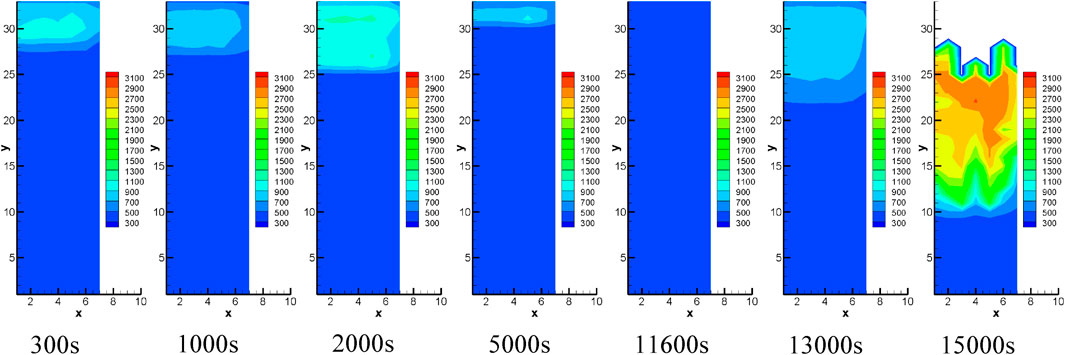
FIGURE 13. Temperature distribution of cladding for optimization strategy 2.
The hydrogen generated in the core and lower plenum is released into the containment through the break position in the primary circuit, which is at the cold leg in loop 1. Hydrogen is most likely to accumulate in the cold leg compartment and the containment compartment. Therefore, the risk of hydrogen explosion in the cold leg compartment and containment compartment is given priority. Figure 14 presents the average mole fraction of uniformly distributed hydrogen in the containment compartment.
FIGURE 14. Mole fraction of hydrogen in the containment compartment.
For the analysis of hydrogen risk in the containment, the flame accelerated to sound velocity and the deflagration to detonation transition (DDT) can be excluded if the average mole fraction of uniformly distributed hydrogen is less than 10% (IAEA, 2011). It can be seen from Figure 14 that the average hydrogen mole fraction in containment for various strategies is much lower than 10%. Consequently, the risk of global detonation in the containment can be eliminated.
For the analysis of hydrogen risk in the cold leg compartment, the ternary characteristic curve for hydrogen deflagration proposed by Shapiro and Moffette (Shapiro and Moffette T, 1957) is used to determine whether hydrogen combustion or explosion occurs. The hydrogen deflagration diagram for various strategies is presented in Figure 15. It can be found that, in all strategies, only the hydrogen combustion zone is reached, which indicates that there is no risk of a violent explosion of hydrogen in the cold leg compartment.
FIGURE 15. Hydrogen deflagration diagram for the cold leg compartment.
It can be concluded that the risk of hydrogen detonation in both the containment and the cold leg compartment is at a low level. The failure of containment integrity due to hydrogen flame acceleration can be excluded.
The risk analysis of overpressure is used to assess the impact of steam generated due to in-vessel injection on the primary system and the containment.
In the calculation, the double-ended guillotine break occurs at the cold leg in loop 1 at 200 s. The failure of pressure boundary makes the primary circuit pressure drop rapidly from 155 bar (as shown in Figure 16). At the same time, a large amount of primary coolant enters the containment, causing the containment pressure to rise rapidly (as presented in Figure 17). When the pressure of the primary circuit drops below the setting value, the ACCs are triggered to quickly inject water into the RPV with a large flow rate, causing the primary circuit pressure to rise briefly. Afterward, due to the continuous evaporation of water in the pressure vessel, the water inventory in the core is gradually reduced. Therefore, the pressure in the primary circuit decreases. The high-temperature steam entering the containment condenses after contacting the cold containment wall surface, causing the pressure in the containment to be reduced. After the water injection in-vessel is implemented, the pressure in the primary circuit and the containment rises again. Meanwhile, the water in the pit continuously evaporates, causing the pressure in the containment to rise continuously.
FIGURE 16. Pressure in the primary system.
FIGURE 17. Pressure in the containment.
Owing to using a small tube diameter to implement the in-vessel injection, the water injection flow rate is limited. Therefore, there is not significant pressure increase in the primary circuit and the containment during the water injection process. Compared with the design without IVI, the pressure increase in the PS and containment does not exceed 2 bar. And the maximum pressure in the containment within 24 h after LB-LOCA does not exceed the design limit of 5.2 bar. Consequently, the integrity of the containment within 24 h after the accident can be guaranteed.
In MIDAC, five mechanisms are considered to analyze the failure risk of a reactor vessel lower head. Ignoring the influence of lower head penetrations, three failure mechanisms of the lower head are analyzed in this paper, including the following:
1) Creep failure: The internal pressure in the vessel and the weight of the molten pool with high temperature may induce the creep failure of the lower head. Once the cumulative creep damage fraction reaches 1.0, the creep failure occurs.
2) Yield failure: The metallic layer may thermally attack and weaken the vessel wall. When the hoop stress load on the RPV lower head exceeds the yield stress, the integrity of the lower head will be lost due to yield failure.
3) Jet ablation failure: The corium jet may cause localized ablation of the lower head. When the ratio between the eroded depth and the lower head wall thickness reaches 1.0, the jet ablation failure occurs.
Figures 18, 19 present, respectively, the creep damage fraction and the comparison between the hoop stress and the yield strength as well as the jet ablation fraction for various strategies. It can be found that the creep damage fraction and the jet ablation fraction are far less than 1.0, and the hoop stress is much smaller than the yield strength. It can be concluded that the integrity of the lower head can be guaranteed after the implementation of IVI.
FIGURE 18. Creep damage fraction.
FIGURE 19. Yield failure and jet ablation fraction.
In the case of overpressure in the primary circuit, the heat transfer tubes of the steam generator may be broken, resulting in an increased risk of fission products from the primary circuit being released into the secondary circuit. The failure of SG tubes in MIDAC is determined by the creep damage fraction. The calculation results show that the creep damage fractions in SG tubes for various strategies are close to 0 during the accidents. It may be explained by the fact that the calculation condition is LB-LOCA, in which the pressure in the primary circuit remains at a low level after the implementation of IVI. Therefore, the temperature and pressure of the saturated steam flowing through the steam generator are low, which has little effect on the creep failure of the heat transfer tubes.
Fission products are divided into 12 groups according to chemical properties in MIDAC, in which the isotope nuclides of Kr, Xe, I, and Cs elements contribute 95.48 and 90.17% to the external radiation dose within 2 h and 30 days after severe accidents. Therefore, the distribution characteristics of nobles and CsI are given priority for the risk analysis of fission product release. Figure 20 presents the mass fraction of CsI in the primary system, containment, and environment, respectively. The variation tendencies of nobles are consistent with those of CsI. Compared with CsI, nobles are more volatile, causing all the nobles in the core to be transported to the containment.
FIGURE 20. Mass fraction of CsI.
During the IVI process in the 40 min 60 mm strategy and optimization strategies 1.1 and 1.2, massive cracks are generated between and within the grains in the fuel pellets with high temperature due to quenching, which is favorable to the release of fission products. Since the core remains submerged in optimization strategy 1.3, the zirconium cladding in the bottom region is not oxidized and damaged. Therefore, the integrity of the zirconium cladding hinders the release of CsI and nobles. The implementation of IVI is earliest in optimization strategy 2, in which the temperature of the entire core is at a low level which prevents the fuel pellets from shattering due to quenching. The release quantities of CsI and nobles are the lowest after the core is exposed again.
The maximum pressure in the containment does not exceed the design limit of 5.2 bar within 24 h after the severe accidents for various strategies. Therefore, the integrity of the containment can be guaranteed. When the containment is intact, the amount of fission products released into the environment through the natural leakage channel of the containment can be neglected. Therefore, the risk of fission products being released into the environment can be eliminated.
In order to improve the margin of the current IVR-ERVC strategy for high-power reactors, two feasible IVI designs are proposed: 1) using the passive IVR water tank to implement simultaneous water injection in-vessel and ex-vessel and 2) using passive SADITs to implement water injection in-vessel. The effectiveness of IVI is performed, and the negative effects after water injection are analyzed by using MIDAC. It can be found that compared with the design without IVI, the early water injection in-vessel can significantly delay the accident process in the core, reducing the maximum decay heat of the molten pool in the lower head and increasing the effectiveness margin of IVR-ERVC; especially, the following can be found:
1) The three optimization strategies in the first IVI design can realize, respectively, that the core is submerged within 6/10/72 h after severe accidents.
2) The second design can significantly reduce the hydrogen production in 3.6 h after severe accidents, providing valuable response time for external emergency measures to be put into operation.
In addition, when the IVI is implemented, the risk of violent explosion of hydrogen in the cold leg compartment and the containment is at a low level. And compared with the design without IVI, the pressure increase in the primary circuit and the containment does not exceed 2 bar after water injection in-vessel. The risk of yield failure, creep failure, and jet ablation failure of the lower head can be eliminated. And the maximum pressure in the containment does not reach the design limit of 5.2 bar within 24 h after severe accidents. Therefore, the integrity of the containment can be guaranteed, and the amount of fission products released into the environment through the natural leakage channel of the containment can be neglected.
Except for HPR1000, the sensitivity analysis conclusions in the paper are also applicable to the Severe Accident Management Guidelines (SAMG) of other reactor types, including AP1000 and CAP1400. Namely, compared with late water injection, early in-vessel water injection has a more obvious effect on delaying the process of accidents in the reactor and increases the safety margin of the current IVR-ERVC strategy for high-power reactors. In the late phase of water injection, it is possible that the debris bed and molten pool present uncoolability, resulting in an insignificant effect of water injection in the reactor, and serious negative risks such as steam explosion may occur. In contrast, in the case of early in-vessel water injection, the uncertainties of the phenomenon and the calculation models of severe accident codes are limited. Meanwhile, the negative risk after water injection is in an acceptable state.
The original contributions presented in the study are included in the article/Supplementary Material, and further inquiries can be directed to the corresponding author.
The authors listed in this article have all made important contributions to the completion of this paper. Among them, PC and XZ completed the main writing of this article. ZW completed the modeling of MIDAC calculation. DZ and SX provided the main ideas for creation.
This work was supported by the National Key R&D Program of China (Grant No. 2019YFB1900702).
Authors PC, ZW, DZ, SX, and XZ were employed by China Nuclear Power Technology Research Institute Co., Ltd.
All claims expressed in this article are solely those of the authors and do not necessarily represent those of their affiliated organizations, or those of the publisher, the editors, and the reviewers. Any product that may be evaluated in this article, or claim that may be made by its manufacturer, is not guaranteed or endorsed by the publisher.
The Supplementary Material for this article can be found online at: https://www.frontiersin.org/articles/10.3389/fenrg.2021.785513/full#supplementary-material
Basu, S., and Ginsberg, T. (1996). A Reassessment of the Potential for an Alpha-Mode Containment Failure and a Review of the Current Understanding of Broader Fuel-Coolant Interaction Issues. Second Steam Explosion Review Group Workshop. Antimicrob. Agents Chemother. 52 (8), 2937–2939.
Carénini, L., Fichot, F., Bakouta, N., Le Tellier, R., Viot, L., Melnikov, I., and Filippov, A. (2019). “Main Outcomes from the IVR Code Benchmark Performed in the IVMR Project,” in Proc. Of the 9th European Review Meeting on Severe Accident Research (ERMSAR2019), 18–20.
Carénini, L., and Fichot, F. (2016). “The Impact of Transient Behavior of Corium in the Lower Head of a Reactor Vessel for In-Vessel Melt Retention Strategies,” in International Conference on Nuclear Engineering, Charlotte, North Carolina, June 26-30, 2016 (American Society of Mechanical Engineers (ASME)), V004T13A009.
Coryell, W., and April, (1994). Summary of Important Results and SCDAP/RELAP5 Analysis for OECD LOFT Experiment LP-FP-2. Idaho Falls: EG&G Idaho. Inc.
Dorsselaere, J. P. V., Fichot, F., and Seiler, J. M. (2006). Views on R&d Needs about In-Vessel Reflooding Issues, with a Focus on Debris Coolability. Nucl. Eng. Des. 236 (19-21), 1976–1990. doi:10.1016/j.nucengdes.2006.03.039
Fichot, F., Carénini, L., Sangiorgi, M., Hermsmeyer, S., Miassoedov, A., Bechta, S., et al. (2018). Some Considerations to Improve the Methodology to Assess In-Vessel Retention Strategy for High-Power Reactors. Ann. Nucl. Energ. 119, 36–45. doi:10.1016/j.anucene.2018.03.040
Fletcher, D. F. (1994). A Review of the Available Information on the Triggering Stage of a Steam Explosion. Nucl. Saf. 35, 1.
Hagen, S., Hofmann, P., Noack, V., Schanz, G., Schumacher, G., and Sepold, L. (1993). Results of SFD Experiment CORA-13 (OECD International Standard Problem 31). Karlsruhe, Germany: No. KFK--5054 Kernforschungszentrum Karlsruhe GmbH (Germany). Hauptabteilung Ingenieurtechnik.
Huhtiniemi, I., and Magallon, D. (2001). Insight into Steam Explosions with Corium Melts in KROTOS. Nucl. Eng. Des. 204 (1-3), 391–400. doi:10.1016/s0029-5493(00)00319-8
IAEA (2011). Mitigation of Hydrogen Hazards in Severe Accidents in Nuclear Power Plants. IAEA-TECDOC-1661.
Jun, T., Jingxi, L. I., Lili, T., and Xuewu, C. (2011). Core Cooling in Pressurized-Water Reactor during Water Injection. Nucl. Sci. Tech. (01), 62–66. doi:10.13538/j.1001-8042/nst.22.60-64
Kymäläinen, O., Tuomisto, H., and Theofanous, T. G. (1997). In-vessel Retention of Corium at the Loviisa Plant. Nucl. Eng. Des. 169 (1-3), 109–130. doi:10.1016/s0029-5493(96)01280-0
Ma, W., Yuan, Y., and Sehgal, B. R. (2016). In-vessel Melt Retention of Pressurized Water Reactors: Historical Review and Future Research Needs. Engineering 2 (1), 103–111. doi:10.1016/j.eng.2016.01.019
Magallon, D., and Bang, K. H. (2007). FCI Phenomena Uncertainties Impacting Predictability of Dynamic Loading of Reactor Structures (Serena Programme). OECD (NEA) Committee on the Safety of Nuclear Installations.
Magallon, D., Huhtiniemi, I., and Hohmann, H. (1999). Lessons Learnt from Faro/termos Corium Melt Quenching Experiments. Nucl. Eng. Des. 189 (1/3), 223–238. doi:10.1016/s0029-5493(98)00274-x
Oh, S. J., and Kim, H. T. (2005). “Effectiveness of External Reactor Vessel Cooling (ERVC) Strategy for APR1400 and Issues of Phenomenological Uncertainties,” in Workshop Proceedings: Evaluation of Uncertainties in Relation to Severe Accidents and Level-2 Probabilistic Safety Analysis, Aix-en-Provence (France), November 7-9, 2005, 7–9.
Sangiorgi, M., and Ezzidi, A. (2015). “In-vessel Melt Retention (IVMR) Analysis of a VVER-1000 NPP,” in In 6th ASTEC user’s club/2nd CESAM workshop.
Shi, G., Gu, P., Lu, W., Wang, J., Cao, K., Zhang, K., et al. (2019). CAP1400 IVR Related Design Features and Assessment. Nucl. Eng. Des. 346, 35–45. doi:10.1016/j.nucengdes.2019.03.002
Theofanous, T. G., Liu, C., Additon, S., Angelini, S., Kymäläinen, O., and Salmassi, T. (1997). In-vessel Coolability and Retention of a Core Melt. Nucl. Eng. Des. 169 (1-3), P35–P42. doi:10.1016/s0029-5493(97)00009-5
Nuclear Regulatory Commission, (1989). Severe Accident Risks: An Assessment of Five U.S. Nuclear Power Plant. NUREG-1150, Revision 1.
Wang, D., Zhang, Y., Chen, R., Su, G. H., Qiu, S., and Tian, W. (2019). Numerical Simulation of Zircaloy-Water Reaction Based on the Moving Particle Semi-implicit Method and Combined Analysis with the Midac Code for the Nuclear-Reactor Core Melting Process. Prog. Nucl. Energ. 118.
Wang, J., Tian, W., Fan, Y., Mao, K., Lu, J., Su, G., et al. (2014). The Development of a Zirconium Oxidation Calculating Program Module for Module In-Vessel Degraded Analysis Code Midac. Prog. Nucl. Energ. 73, 162–171. doi:10.1016/j.pnucene.2014.02.006
Wang, J., Tian, W., Zhang, Y., Chen, L., Li, L., Zhang, L., et al. (2014). The Development of Module In-Vessel Degraded Severe Accident Analysis Code Midac and the Relevant Research for Cpr1000 during the Station Blackout Scenario. Prog. Nucl. Energ. 76 (sep), 44–54. doi:10.1016/j.pnucene.2014.05.015
Wright, A. L. (1994). Primary System Fission Product Release and Transport. Oak Ridge, Tennessee, United States.
Wu, S., Zhang, Y., Wang, D., Tian, W., Qiu, S., and Su, G. H. (2021). Assessment of the Severe Accident Code Midac Based on Froma, Quench-06&16 Experiments. Xi’an, China: Nuclear Engineering and Technology.
Xing, J., Song, D., and Wu, Y. (2016). HPR1000: Advanced Pressurized Water Reactor with Active and Passive Safety. Engineering 2 (1), 79–87. doi:10.1016/j.eng.2016.01.017
Zhan, D., Zhao, X., Xia, S., Chen, P., and Chen, H. (2020). Studies on Key Effect Factors of Natural Circulation Characteristics for Advanced PWR Reactor Cavity Flooding System. Sci. Techn. Nucl. Installations 2020, 1–11. doi:10.1155/2020/4765046
Keywords: severe accidents, IVR-ERVC, in-vessel injection, optimized design, negative effect assessment
Citation: Chen P, Wu Z, Zhan D, Xia S and Zhao X (2022) Research on Optimized Design of In-Vessel Retention–External Reactor Vessel Cooling Strategy and Negative Effect Assessment. Front. Energy Res. 9:785513. doi: 10.3389/fenrg.2021.785513
Received: 29 September 2021; Accepted: 06 December 2021;
Published: 24 February 2022.
Edited by:
Yapei Zhang, Xi’an Jiaotong University, ChinaReviewed by:
Shanshan Bu, Chongqing University of Technology, ChinaCopyright © 2022 Chen, Wu, Zhan, Xia and Zhao. This is an open-access article distributed under the terms of the Creative Commons Attribution License (CC BY). The use, distribution or reproduction in other forums is permitted, provided the original author(s) and the copyright owner(s) are credited and that the original publication in this journal is cited, in accordance with accepted academic practice. No use, distribution or reproduction is permitted which does not comply with these terms.
*Correspondence: Xinhai Zhao, emhhb3hpbmhhaTJAY2ducGMuY29tLmNu
Disclaimer: All claims expressed in this article are solely those of the authors and do not necessarily represent those of their affiliated organizations, or those of the publisher, the editors and the reviewers. Any product that may be evaluated in this article or claim that may be made by its manufacturer is not guaranteed or endorsed by the publisher.
Research integrity at Frontiers
Learn more about the work of our research integrity team to safeguard the quality of each article we publish.