 Chen Zhao
 Xingjie Peng
 Hongbo Zhang
- Science and Technology on Reactor System Design Technology Laboratory, Nuclear Power Institute of China, Chengdu, China
In order to establish the next-generation reactor physics calculation method based on the numerical nuclear reactor technology and realize high-fidelity modeling and calculation, a new numerical nuclear reactor neutronics code SHARK is developed. The code is based on the direct transport method with construct solid geometry (CSG) method, advanced subgroup resonance method, direct transport MOC method in rectangle and hexagonal geometry, large-scale parallel, and CMFD acceleration method. The C5G7, macro BEAVRS and VERA benchmarks are verified to show the accuracy of the code and method. Numerical results show good accuracy and calculation performance of SHARK, and the direct transport method can be adopted on numerical nuclear reactor calculation.
1 Introduction
Numerical nuclear reactor is based on the multi-physics coupling calculation with accurate theory and physical model from first principles. In this way, the approximation from experience and artificial adjustment is eliminated to the maximum extent. With the high-performance computing platform, high-fidelity and high-distinguishability numerical calculation for nuclear reactor is conducted to decrease the conservation of safety analysis (Casl, 2010; CASL Project Summary Slides, 2011). In numerical nuclear reactor physics calculation, the direct transport method avoids the spatial and energy group homogenization in the traditional two-step method. Besides, the resolution can be improved to the level of flat source region, and micro-phenomenon can be simulated.
The research of the direct transport method has become a hotspot in numerical nuclear reactor physics calculation. Several direct transport codes have been developed for numerical nuclear reactor physics calculation, including MPACT (Kelley and Larsen, 2013), nTRACER(Jung, 2013), DeCART(Hursin, 2010), STREAM (Choi et al., 2019), NECP-X (Chen et al., 2018), and PANX (Zhang et al., 2017a; Zhang et al., 2017b). PWR whole-core multi-physics coupling direct calculation has been conducted, and numerical results show good accuracy. However, most numerical nuclear reactor technologies are focused on the large-scale pressured water reactor. The direct transport method needs to be improved for further application on advanced nuclear reactors in the future.
In this paper, a new numerical nuclear reactor neutronics code SHARK (Zhao et al., 2021a; Zhao et al., 2021b) is developed, which is the initial abbreviation of the Simulation-based High-fidelity Advanced Reactor physics Kit. The traditional technical route is applied in the SHARK code, including geometry modeling, resonance method, and transport method. A significant objective of the code design lies in the calculation ability for advanced numerical nuclear reactor with complex geometry. Therefore, geometry adaptability is one of the most important characteristics for SHARK. The detailed description of framework and methods in each module will be introduced.
2 Framework of Simulation-based High-fidelity Advanced Reactor physics Kit
The numerical nuclear reactor neutronics code SHARK has four modules, including utilities, geometry, calculation, and UI. The overall framework and detailed modules of SHARK are shown in Figure 1.
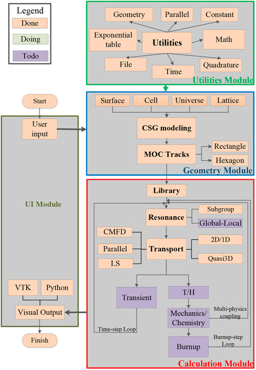
FIGURE 1. The framework and modules of Simulation-based High-fidelity Advanced Reactor physics Kit (SHARK).
In the utilities module, basic programming kits are provided, such as the math library, time function, and parallel parameters. In the geometry module, the reactor geometry model is built by surface, cell, universe, and lattice. Two-dimensional characteristic rays are generated in each layer. It supports rectangle and hexagonal ray tracing. The calculation module is the kernel of SHARK and includes several calculation sub-modules, including library, resonance, transport, transient, thermal-hydraulics, mechanics/chemistry multi-physics coupling, and burnup. Up to now, library, resonance, and transport have already been realized in SHARK. Other sub-modules will be developed in the future. In the UI module, user input and visual output are executed with Python programming language for expanding the visualization ability. As for programming, C++/Python hybrid programming is adopted to combine the data processing for Python and the numerical calculation for C++. Besides, object-oriented programming improves the readability, modularization, and reusability.
3 Geometry modeling
In the initial design of SHARK, two significant objectives are the accurate geometry modeling and calculation abilities for advanced numerical nuclear reactor with complex geometry. In SHARK, the constructive solid geometry (CSG) (Cao et al., 2019) method is adopted. The geometry model is built with objects by regular Boolean operation in the CSG method. In the geometry modeling procedure, several typical objects need to be predefined, including surface, cell, universe, and lattice. In this way, the geometry modeling ability can be extended to arbitrary geometry theoretically with complicated CSG objects. In the UI module, the geometry modeling can be visually displayed to verify the modeling correction. Complicated geometry modeling of hexagonal assembly and plate-type assembly has already been realized in SHARK. The geometry modeling of the plate-type assembly and the JRR-3 reactor (Iwasaki et al., 1985; Liu et al., 2015) are shown in the Figure 2.
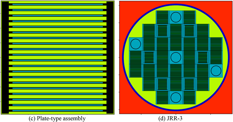
FIGURE 2. Complicated geometry modeling of SHARK.
4 Ray tracing
SHARK is a MOC-based numerical nuclear reactor neutronics code, and ray tracing is an important section in the code design. Assembly module ray tracing method (Hong and Cho, 1998) is applied in ray tracing to save the memory cost. Up to now, rectangle and hexagon modular ray tracing has been developed in SHARK with the established method (Cho et al., 2008; Chen et al., 2018). In the future, the long characteristic method (Suslov, 2001) will be added for complicated geometry cases without regular assembly structure.
5 Library and resonance method
5.1 Library
The multi-group cross-section library in SHARK is processed by NJOY (Muir et al., 2016) based on ENDF/B-VI.8. The 45-group energy group structure is applied in SHARK, which has been verified in the HELIOS method (HELIOS Methods, 2001). A new library based on the ENDF/B-VII.0 will be processed and researched in the future.
5.2 The subgroup resonance method
The subgroup method based on the equivalent cross-section interpolation table (Cullen, 1977; Wemple et al., 2008) is applied in resonance calculation. The diagram of the subgroup method is shown in Figure 3.
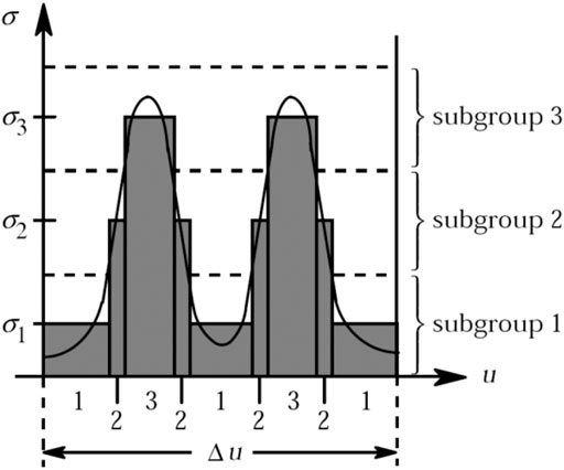
FIGURE 3. The diagram of subgroup resonance method.
In the resonance region, according to the subgroup method, the cross section can be calculated in the form of the subgroup, shown as Eq. 1.
where,
In the equation,
where
6 Direct transport method
6.1 2D/1D and quasi-3D methods
As for the direct transport method, two options are provided in SHARK, including the 2D/1D method and the quasi-3D method. The 2D/1D method has the efficiency and memory cost advantages on most cases such as the C5G7 benchmark and large-scale PWR cases. However, the 2D/1D method will suffer instability issues considering the negative sources introduced by traverse leakage terms (Stimpson et al., 2013; Zhao et al., 2018). Axial difference relationship is introduced in the quasi-3D method and negative sources can be avoided in the two-dimensional MOC calculation. Therefore, the quasi-3D method has better stability performance in theory with poor efficiency. Besides, no isotropic approximation is introduced in the equation derivation of the quasi-3D method. The quasi-3D method has better calculation accuracy in the strong anisotropic cases, such as the KUCA benchmark. The detailed analysis and comparison of these two methods can be found in previous work (Zhao et al., 2021b).
6.2 odCMFD acceleration method
Coarse-mesh finite difference (CMFD) method (Zhu et al., 2016; Li et al., 2020) has already become an established method in the high-order calculation, especially in the direct transport method. Several advanced CMFD acceleration methods, such as odCMFD (Zhu et al., 2016) and lpCMFD (Li et al., 2020), have been proposed these years. These methods have little variations on the basic theory of the CMFD method. Current diffusion and correction coefficients are introduced with the high-order results of net currents and fluxes. The diagram of CMFD acceleration in SHARK is shown in Figure 4. The MOC-based transport calculation is conducted to provide radial, axial net currents, and fine-mesh fluxes. In the CMFD module, pin-homogenized fluxes, cross-sections, and coefficients need to be prepared before eigenvalue calculation. Eigenvalue and fine-mesh fluxes are updated by CMFD results. In this way, the convergence of eigenvalue iteration can be accelerated.

FIGURE 4. The diagram of the coarse-mesh finite difference (CMFD) acceleration in SHARK.
However, the traditional CMFD method suffers the poor stability issue. In SHARK, the odCMFD (Zhu et al., 2016) method is applied. In the theory of odCMFD, an additive component is added in the diffusion coefficient calculation, shown as Eq. 5.
where,
6.3 Spatial parallel method
Advanced parallel algorithm is applied in the spatial domain-decomposition method in SHARK. Memory cost can be divided and decomposed before calculation. Ray sweeping happens on the certain domain for each CPU, and the communication only happens on the inner boundary for each domain. In this way, memory cost can be decreased for each node, and the large-scale calculation can be realized. Furthermore, non-blocking strategy is applied for communication, which improves parallel efficiency. The diagram of domain decomposition in SHARK is shown in Figure 5.
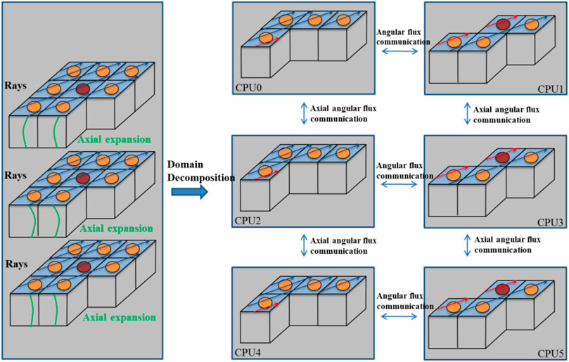
FIGURE 5. The diagram of domain decomposition in SHARK.
7 Numerical results
7.1 The macro benchmark
7.1.1 Hexagonal assembly case
To validate the hexagonal calculation ability, a hexagonal assembly seven-group case is designed, as is shown in the Figure 6. Ten rings are arranged, including three MOX-8.7% rings, MOX-7% ring, MOX-4.3% ring, control rod ring, 3 UO2 fuel rings, and fission chamber from outside to inside. The assembly box can be explicitly modeled. The pitch of the hexagonal pin cell is 0.91 cm. Radiuses of the inner and outer fuel pellets are 0.33 and 0.39 cm. Thicknesses of the assembly box and assembly gap are 0.26 and 0.22 cm separately. The multi-group cross-sections are from the C5G7 benchmark (OECD, 2005).
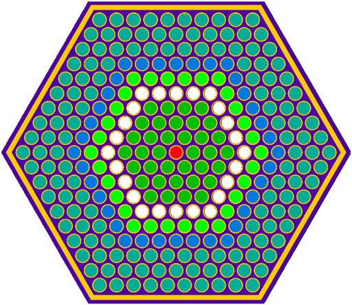
FIGURE 6. Hexagonal assembly geometry modeling of SHARK.
Reference result is from the Monte Carlo code OpenMC (Romano and Forget, 2013). Three billion active particles are used (3,000 generations consisting of 1,000,000 neutrons per generation, of which 100 generations are skipped). The standard deviation of the Monte Carlo result is 1 pcm. As for SHARK, 32 flat source regions are divided in the fuel rod pin cell. Sixty azimuthal angles, six polar angles, Yamamoto quadrature set, and 0.03-cm ray spacing are adopted. Eigenvalue and fission rate distribution results are shown in the Table 1. The pin-cell fission rate distribution results are shown in the Figure 7. As is shown in the table, the eigenvalue difference is 54 pcm, and the maximum pin-cell fission rate difference is 0.2%. These results show the good accuracy of the hexagonal calculation ability in SHARK.
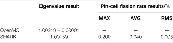
TABLE 1. The eigenvalue and fission rate results of the hexagonal assembly case.
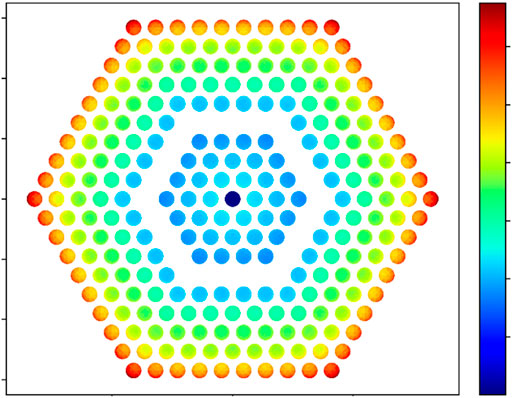
FIGURE 7. The pin-cell fission rate results of the hexagonal assembly case.
7.1.2 Pin-cell geometry cases
The pin-cell geometry case is the basic calculation target for SHARK. The KUCA benchmark, C5G7 benchmark, and macro BEAVRS benchmark have already been applied in the validation of the transport module (Zhao et al., 2021b). Geometry modeling of these three cases is shown in Figure 8.
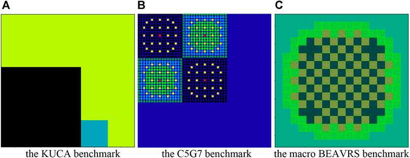
FIGURE 8. Modeling of the pin-cell geometry cases with SHARK.
In the validation of these three cases, the 2D/1D transport method and the quasi-3D method have been compared with numerical results. In the KUCA benchmark and the C5G7 benchmark, the quasi-3D method shows better accuracy because of the strong anisotropic effect in these two cases. In the macro BEAVRS benchmark, the 2D/1D method has efficiency advantage.
Besides, the odCMFD acceleration and spatial parallel method also show good effect on the direct transport calculation. The traditional CMFD method without additive component in the diffusion coefficient has divergence problem in the KUCA and C5G7 benchmark calculation. The odCMFD method solves the issue and improves the stability of the traditional CMFD method. As for the spatial parallel method, 578 cores are adopted for the large-scale parallel calculation in the macro BEAVRS benchmark. The parallel algorithm improves the calculation efficiency, as well as realizing the memory cost decomposition and decreasing the memory cost for each node. The detailed numerical results of the macro benchmarks can be found in previous research (Zhao et al., 2021b).
7.2 The micro benchmark
7.2.1 The VERA-2 lattice benchmark
The VERA benchmark (Godfrey, 2014) is a series of benchmark published in the CASL project. The benchmark is modeled by Watts Bar nuclear plant and includes several cases from two-dimensional pin cell to three-dimensional whole core.
VERA-2 consists of 16 two-dimensional lattice cases in the VERA benchmark. Fuel enrichment, burnup poison, control rod, and gadolinium rod are considered in the VERA-2 benchmark.
Reference results are from the Monte Carlo code KENO using ENDF/B-VI.8. The calculation condition for SHARK is eight azimuthal angles and three polar angles in each octant with Yamamoto optimal quadrature set. The ray spacing is 0.01 cm. The library used in the subgroup method is also generated from ENDF/B-VI.8. Results of the VERA-2 benchmark are shown in Table 2. The average eigenvalue difference is 152 pcm, and the average maximum pin power difference is 1.34%. These results show the good accuracy of the subgroup resonance method in SHARK. As for the 2G and 2H cases, both the eigenvalue and pin power differences are relatively large. It is caused by the complex resonance phenomenon for AIC and B4C control rod absorbers. It needs to be researched in the future.
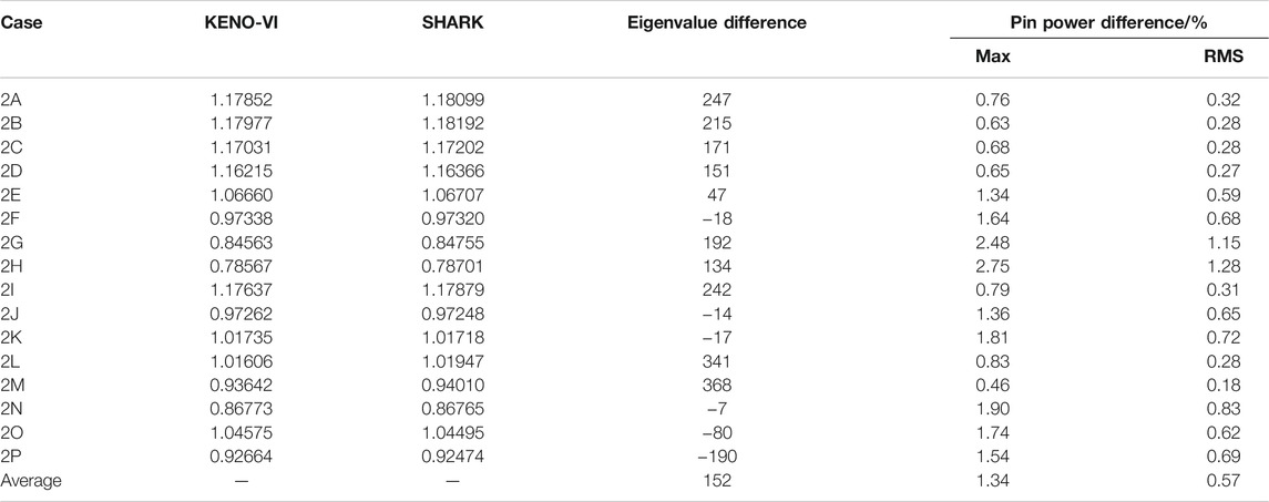
TABLE 2. Numerical results of the VERA-2 benchmark.
7.2.2 The VERA-3 assembly benchmark
The VERA-3 assembly benchmark is a 3D single-assembly problem: Case 3A is a 3.1 w/o fuel assembly without burnable absorber at 600 K, and Case 3B is a 2.619 w/o fuel assembly with 16 Pyrex rods at 565 K. In addition to the radial arrangement, the benchmark problem tries to restore the structural details of the fuel assembly in the axial direction, such as end plugs, plenums, springs, nozzles, core plates, and spacer grids. Therefore, the problem provides a full picture of the ability of the software to simulate the heterogeneous effects of PWR assembly in the axial direction.
Two 3D assembly cases are modeled faithfully and accurately with SHARK. The axial active segment is divided into 49 layers, which is exactly consistent with the reference solution. Inflow transport correction has been applied in calculation of the VERA-3 benchmark. The 2D/1D solver is adopted as the default choice in micro cases considering the better efficiency performance. Compared with the reference results from KENO-VI, the results of the VERA-3 benchmark in SHARK are given in Table 3 and the radial and axial pin power results are shown in Figure 9 and 10. Deviations of eigenvalue results are less than 200 pcm, and the maximum radial pin power differences are 0.15% and 0.16% for the VERA-3A and VERA-3B cases. As for the axial power distribution, the maximum deviation of SHARK is only 2.61% and occurs in the low-power region near the top reflector layer. Meanwhile, the axial average (AVG) error and RMS error also reflect the accuracy of the program in modeling the axial heterogeneousity. As seen in Figure 10A, B, the axial power shape fits the KENO-VI reference well, and the spacer grid effects are accurately represented.
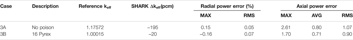
TABLE 3. Numerical results of the VERA-3 benchmark.
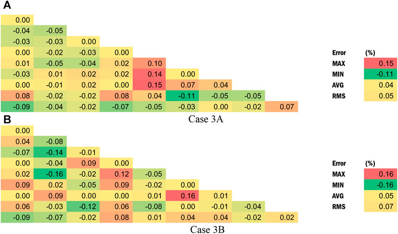
FIGURE 9. Radial pin power error distribution of VERA-3 benchmark.
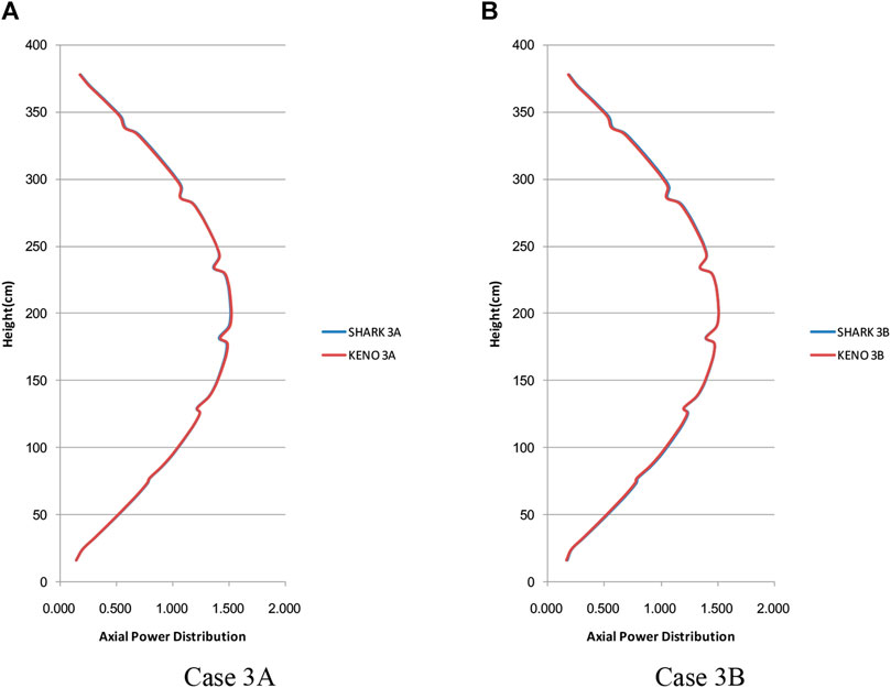
FIGURE 10. Axial power distribution of VERA Problem #3.
8 Conclusion
In this paper, a numerical nuclear reactor neutronics code SHARK is newly developed in the Nuclear Power Institute of China (NPIC). The framework and several significant sections of SHARK are introduced, including geometry modeling, characteristic ray tracing, library, subgroup resonance method, 2D/1D and quasi-3D direct transport method, odCMFD acceleration, and spatial parallel method. In numerical results, verification of SHARK is conducted by several macro and micro benchmark cases, including the macro hexagonal assembly case, the micro VERA-2 lattice benchmark, and the VERA-3 assembly benchmark. Eigenvalue difference is 54 pcm, and maximum pin power difference is 0.2% for the macro hexagonal assembly case. As for the micro benchmark, axial power differences are 2.61% and 1.70% for VERA-3A and VERA-3B benchmarks separately. These results show the good accuracy of SHARK.
Data Availability Statement
The original contributions presented in the study are included in the article/Supplementary Material. Further inquiries can be directed to the corresponding author.
Author Contributions
All authors listed have made a substantial, direct, and intellectual contribution to the work and approved it for publication.
Funding
This work is supported by the National Natural Science Foundation of China (Grant No. 12005214, 11905214) and the China Association for Science and Technology (Young Elite Scientists Sponsorship Program 2019QNRC001).
Conflict of Interest
Authors CZ, XP, HZ, WZ, JR, KL, ZC, ZG, WZ, and QL were employed by the company Nuclear Power Institute of China.
Publisher’s Note
All claims expressed in this article are solely those of the authors and do not necessarily represent those of their affiliated organizations, or those of the publisher, the editors, and the reviewers. Any product that may be evaluated in this article, or claim that may be made by its manufacturer, is not guaranteed or endorsed by the publisher.
References
Cao, L., Liu, Z. Y., Cao, L. Z., He, Q., and Zhou, X. (2019). “Implementation and Application of the CSG Method in the NECP-X Code[C],” in 27th International Conference on Nuclear Engineering (ICONE-27), Ibaraki, Japan, May 19–24, 2019.
Casl, D. B. (2010). The Consortium for Advanced Simulation of Light Water Reactors[R]. Bulletin of the American Physical Society.
CASL Project Summary Slides (2011). CASL: The Consortium for Advanced Simulation of Light Water Reactors. CASL-U-2011-0137-000.
Chen, J., Liu, Z., Zhao, C., He, Q., Zu, T., Cao, L., et al. (2018). A New High-Fidelity Neutronics Code NECP-X. Ann. Nucl. Energ. 116, 417–428. doi:10.1016/j.anucene.2018.02.049
Cho, J. Y., Kim, K. S., Shim, H. J., Song, J. S., Lee, C. C., and Joo, H. G. (2008). Whole Core Transport Calculation Employing Hexagonal Modular Ray Tracing and CMFD Formulation[J]. J. Nucl. Sci. Techn. 45 (8). doi:10.1080/18811248.2008.9711475
Choi, S., Choe, J., Hoang, K., Lee, W., Kim, W., Kim, H., et al. (2019). Recent Development Status of Neutron Transport Code STREAM[C]. Korea: Transactions of the Korean Nuclear Society Spring Meeting Jeju.
Cullen, D. E. (1977). Calculation of Probability Table Parameters to Include Intermediate Resonance Self-Shielding. LLNL.
Godfrey, A. T. (2014). VERA Core Physics Benchmark Progression Problem Specifications, Revision 3[R]. CASL-U-2012-0131-004, CASL.
Hong, S. G., and Cho, N. Z. (1998). CRX: A Code for Rectangular and Hexagonal Lattices Based on the Method of Characteristics. Ann. Nucl. Energ. 25 (8), 547–565. doi:10.1016/s0306-4549(97)00113-8
Hursin, M. (2010). Full Core, Heterogeneous, Time Dependent Neutron Transport Calculation with the 3D Code DeCART[D]. Berkeley, CA: University of California, Berkeley.
Iwasaki, J., Tsuruta, H., and Ichikawa, H. (1985). Neutronics Calculation of Upgraded JRR-3[R]. JAERI-M, 85–062.
Jung, Y. S. (2013). Development of Practical Numerical Nuclear Reactor for High Fidelity Core analysis[D]. Korea: Seoul National University.
Kelley, B. W., and Larsen, E. W. (2013). “2D/1D Approximations to the 3D Neutron Transport Equation,” in I: Theory,” Proc. M&C 2013, Sun Valley, ID, May 5–9, 2013.
Li, J., Xu, Y., Wang, D., and Shen, C. (2020). “Demonstration of a Linear Prolongation CMFD Method on MOC[C],” in PHYSOR2020, Cambridge, United Kingdom, March 29–April 2, 2020.
Liu, S., Wang, G., Wu, G., and Wang, K. (2015). Neutronics Comparative Analysis of Plate-type Research Reactor Using Deterministic and Stochastic Methods. Ann. Nucl. Energ. 79, 133–142. doi:10.1016/j.anucene.2015.01.027
Muir, D. W., Boicourt, R. M., Kahler, A. C., and Jeremy Lloyd, C. (2016). The NJOY Nuclear Data Processing System, Version 2016. Los Alamos: Los Alamos National Laboratory. Available at: https://www.osti.gov/biblio/1338791.
OECD (2005). Benchmark on Deterministic Transport Calculations Without Spatial Homogenization (MOX Fuel Assembly 3-D Extension Case)[J]. OECD/NEA Report, Nucl. Sci. NEA/NSC/DOC 2005, 16.
Romano, P. K., and Forget, B. (2013). The OpenMC Monte Carlo Particle Transport Code. Ann. Nucl. Energ. 51, 274–281. doi:10.1016/j.anucene.2012.06.040
Stimpson, S., Young, M., Collins, B., Kelly, B., and Downar, T. (2013). “Assessment and Improvement of the 2D/1D Method Stability in DeCART[C],” in M&C 2013, Sun Valley, ID, May 5–9, 2013.
Suslov, I. (2001). Improvements in the Long Characteristics Method and Their Efficiency for Deep Penetration Calculations. Prog. Nucl. Energ. 39 (2), 223–242. doi:10.1016/s0149-1970(01)00014-2
Wemple, C. A., Gheorghiu, H. N., Stamm’ler, R. J. J., and Eduardo, V. (2008). The HELIOS-2 Lattice Physics code[J]. Interlaken, Switzerland: Physor2008.
Zhang, T., Wang, Y., Lewis, E., Smith, M. A., Yang, W. S., and Wu, H. (2017). A Three-Dimensional Variational Nodal Method for Pin-Resolved Neutron Transport Analysis of Pressurized Water Reactors [J]. Nucl. Sci. Eng. 188 (2), 160–174. doi:10.1080/00295639.2017.1350002
Zhang, T., Lewis, E. E., Smith, M. A., Yang, W. S., and Wu, H. (2017). A Variational Nodal Approach to 2D/1D Pin Resolved Neutron Transport for Pressurized Water Reactors. Nucl. Sci. Eng. 186, 120–133. doi:10.1080/00295639.2016.1273023
Zhao, C., Peng, X. J., Zhang, H. B., Zhao, W., Li, Q., and Chen, Z. (2021). Analysis and Comparison of the 2D/1D and Quasi-3D Methods with the Direct Transport Code SHARK[J]. Nucl. Eng. Techn. doi:10.1016/j.net.2021.07.038
Zhao, C., Liu, Z., Liang, L., Chen, J., Cao, L., and Wu, H. (2018). Improved Leakage Splitting Method for the 2D/1D Transport Calculation. Prog. Nucl. Energ. 105, 202–210. doi:10.1016/j.pnucene.2018.01.007
Zhao, C., Peng, X., Zhang, H., Zhao, W., Chen, Z., and Li, Q. (2021). A Linear Source Scheme for the 2D/1D Transport Method in SHARK. Ann. Nucl. Energ. 161, 108479. doi:10.1016/j.anucene.2021.108479
Keywords: numerical nuclear reactor, resonance method, direct transport method, shark, vera
Citation: Zhao C, Peng X, Zhang H, Zhao W, Chen Z, Rao J, Liu K, Gong Z, Zeng W and Li Q (2021) A New Numerical Nuclear Reactor Neutronics Code SHARK. Front. Energy Res. 9:784247. doi: 10.3389/fenrg.2021.784247
Received: 27 September 2021; Accepted: 11 October 2021;
Published: 08 December 2021.
Edited by:
Tengfei Zhang, Shanghai Jiao Tong University, ChinaReviewed by:
Donghao He, Shanghai Jiao Tong University, ChinaLiang Liang, Harbin Engineering University, China
Copyright © 2021 Zhao, Peng, Zhang, Zhao, Chen, Rao, Liu, Gong, Zeng and Li. This is an open-access article distributed under the terms of the Creative Commons Attribution License (CC BY). The use, distribution or reproduction in other forums is permitted, provided the original author(s) and the copyright owner(s) are credited and that the original publication in this journal is cited, in accordance with accepted academic practice. No use, distribution or reproduction is permitted which does not comply with these terms.
*Correspondence: Xingjie Peng, cGVuZ3hpbmdqaWV0c0AxMjYuY29t