- College of Automation, Central South University, Changsha, China
Grid-tied inverter is the prominent component of the three-phase dual-stage photovoltaic (PV) grid-tied power generation system. However, the disturbances caused by dead time effect will pose the reduction of grid-tied current quality and even cause the imbalance of inverter itself or other circuit devices. In this paper, a current control strategy is proposed to damp dead time effect for the three-phase dual-stage PV grid-tied inverter system, and its design, stability analysis, and implementation are carried out. First, the inverter model is modified by regarding the dq reference frame coupling terms, uncertainties, and external and internal disturbances as an unknown lumped disturbance. Then, a current control scheme based on compensation of equivalent input disturbance is introduced, and it estimates and compensates the unknown lumped disturbance, which effectively realizes the inverter model decoupling and comprehensive disturbance rejection. Last, simulation results demonstrate the effectiveness and superiority of the proposed current controller.
1 Introduction
As one of the most promising new energy power generation technologies, photovoltaic (PV) power generation has attracted worldwide attention, and it is worth mentioning that China has the highest installed capacity of PV power generation in the world since 2015 (Xiao, 2021). The grid-tied inverter is the key to the energy exchange process between PV power generation and the grid (Zammit et al., 2021). Actually, to prevent the inverter from short circuit phenomenon caused by the switches on the same phase leg at the same time, it is inevitable to add some dead time to the on/off moments of drive signal. However, the dead time effect will lead to harmonics in the output voltage of the inverter, especially at low order of fundamental frequency (Chen et al., 2018), and then, it brings the serious distortion into the output grid-tied current. The ac multi-frequency periodic disturbances caused by dead time effect pose the reduction of inverter output quality (Lai et al., 2021) and even cause the imbalance of inverter itself or other circuit devices. In addition, the inherent nonlinearity and grid voltage distortion of grid-tied inverter also reduce the grid-tied current quality.
To minimize the total harmonic distortion (THD) level, many current controllers are employed to enhance superior grid-tied current quality, such as proportional multi-resonant controller (Bag et al., 2018; Liu et al., 2013), repetitive controller (RC) (Yang et al., 2016; Li et al., 2020; Xie et al., 2021), and model predictive controller (Hu et al., 2015; Sebaaly et al., 2018). However, among them, the trade-offs between tracking and uncertain disturbance suppression need to be made, due to the single degree of freedom structures. In the recent years, some disturbance and uncertainty estimation and attenuation control methods with two degrees of freedom are proposed to balance the two conflicting requirements between tracking and suppressing uncertain disturbances simultaneously, such as the active disturbance rejection control (ADRC) method (Yu and Hu, 2019; Cao et al., 2020), the disturbance observer-based control (DOBC) method (Errouissi and Al-Durra, 2019, 2018; Errouissi et al., 2021), and the uncertainty and disturbance estimator-based control method (Wang et al., 2016; Ye and Xiong, 2018; Wu et al., 2020). The ADRC method is a powerful technology by regarding the model as a cascade-integral model with a lumped disturbance. It does not rely on precise system models but enlarge the lumped disturbance, so the output characteristics may deviate from the ideal form. In the work of Errouissi and Al-Durra (2018), feedback linearization control combined with DOBC is used to estimate and compensate the disturbance for grid-tied inverter, but the low-pass filter order is usually higher than the plant.
Because the control input is used to improve disturbance suppression ability in control system, obviously, it is more reasonable to suppress the influence of disturbances and uncertainties on the control input channel than themselves. The equivalent input disturbance (EID) control method focuses on the characteristic of control system, that is, only the control input can be used to suppress disturbance, and the EID method directly produces a control signal on the control input channel to compensate the equivalent influence of disturbance (Miyamoto et al., 2016; Du et al., 2021). Motivated by it, this paper proposes a new current controller based on compensation of EID for the three-phase dual-stage PV grid-tied inverter system with considering dead time effect. The controller can effectively realize model decoupling and comprehensive disturbance rejection without requiring prior information. This paper is organized as follows: Section 2 introduces the three-phase dual-stage PV grid-tied inverter system and builds system model. Section 3 modifies the system model and designs the EID-based current controller, consisting of gain module, internal model, state feedback controller, state observer, and EID estimator. In addition, the stability criterion is given based on small gain theory. Section 4 presents the simulation setup and results. Last, some conclusions are derived in Section 5.
2 Plant Modeling
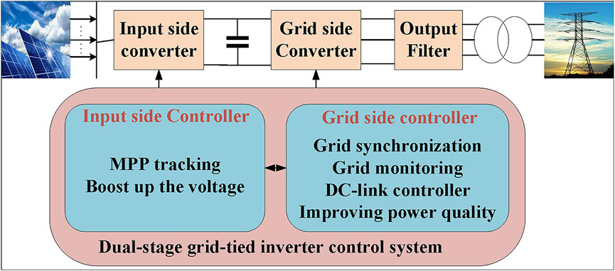
The typical topology of the three-phase dual-stage PV grid-tied inverter system is shown in Figure 1, consisting of the PV power generation system, input side converter, grid side converter, output filter, transformer, and grid. In an input converter based on the maximum power point (MPP) tracking algorithm and boost circuit, the output voltage of the PV system is modulated to an appropriate value as the input of the inverter and then connected to the power grid after filtering circuit and transformer.
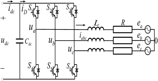
The circuit diagram of the later-stage grid-tied system is shown in Figure 2. The voltage-type three-phase full-bridge inverter composed of six IGBT modules. The output-side is connected with the filtering circuit and the grid.
The expression of grid voltage can be obtained as follows:
where L is the filtering inductance of ac-side; ia, ib, and ic are grid-tied currents; ua, ub, and uc are inverter terminal voltages; R is the equivalent series resistance of the filtering inductance; and ea, eb, and ec are grid voltages.
For the three-phase symmetric system, there are
The expression of the DC side node current is described as follows:
where Cdc represents the dc side capacitance, udc represents the DC side voltage, and idc represents the output current of the former Boost transform circuit.
The grid-tied inverter model in Eqs. 1–3 can be rewritten as follows:
where iD represents the DC side current, and Sa, Sb, and Sc represent the on-off coefficients of the switch tube. Because each mathematical quantity is a transient three-phase AC variable, the space vector transformation is used to transform the inverter model to the dq reference frame, as follows:
where ud, uq and id, iq represent the component of grid voltage and grid-tied current on the d- and q axes. ω is the rotation angular frequency. Obviously, the existence of ωLid and ωLiq causes id and iq to be cross-coupled to each other.
3 Design of EID-Based Current Controller
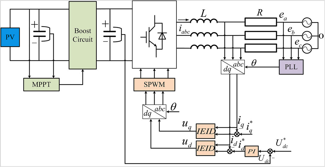
The overall control block diagram of EID-based current control system for three-phase dual-stage PV grid-tied inverter is shown in Figure 3. The front stage adopts MPPT + BOOST circuit. The later-stage grid-tied inverter adopts the voltage and current double closed-loop vector control strategy in the dq reference frame, where the PI controller is used for the outer voltage loop and the EID-based controller is used for the inner current loop.
3.1 Modified Model
The basic idea behind EID can be illustrated by a conceptual diagram as Figure 4. If for all t ≥ 0, the output of Figure 4A,B is the same that always stands up, then the disturbance de(t) is called EID of d(t); as shown in Figure 4C, the disturbance can be obtained by EID estimator and then inverse feedback it to input channel to eliminate the influence of de(t) on the output y(t). Generally, the grid voltage feedforward method is used to decouple in the dq reference (Eq. 5). However, its decoupling performance may be reduced because of the communication time delay from grid voltage sensor to controller. In this paper, the model is modified by regarding the coupling terms and grid voltage disturbances as system disturbances together. Transform Eq. 5 into Eq. 6 that
considering the existence of disturbance signals in the disturbance input channel, then state space (Eq. 7) is obtained
where dcp(t) is the disturbance caused by the coupling terms, d1(t) is the disturbance caused by the fluctuation of the grid and the dead time effect, and d2(t) is the disturbance caused by the uncertainties of internal parameters.
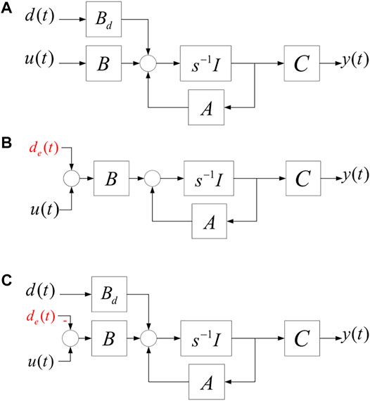
FIGURE 4. Conceptual diagram of EID: (A) plant with disturbance, (B) plant with EID, and (C) plant with EID compensation.
All the disturbances in Eq. 7are lumped, and the modified model Eq. 8 is obtained:
where
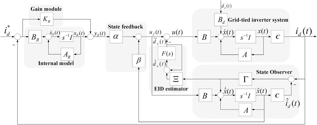
Obviously, de(t) is composed of coupling terms and comprehensive disturbances. The purpose of model decoupling and comprehensive disturbance suppression can be achieved by eliminating de(t). Figure 5 shows the configuration of the EID-based d-axis current control system for system Eq. 8. It is composed of five parts: gain module, internal model, state feedback controller, state observer, and EID estimator. The separation theory (Anderson and Moore, 2007) holds for the system, so each part can be designed separately. The proposed EID-based controller directly estimates the lumped disturbance de(t) and adds it to the control signal
3.2 Internal Model and Gain Module
The internal model is used to accurately track the reference input; its form is shown in Eq. 9:
However, the inertial link and integral action will lead to response delay. To improve the dynamic performance of the internal model, a gain module Ks is proposed to parallel connect with the internal model in this paper. The state equation obtained by parallel connection gain Ks with the internal model is shown in Eq. 10:
3.3 State-Feedback Controller
Assuming there is no disturbance, the augmented state system is as follows, which consists of the internal model and the plant:
where gain K = [α,β]⊤,
To design the state-feedback gain, we build the quadratic performance index (Eq. 12), which is relative to the state and control:
Select an appropriate diagonal matrix QK > 0 and a real scalar RK > 0 to minimize Eq. 12, and then,
3.4 EID Estimator
The state observer of EID controller is constructed as follows:
Defining
If there exists a control signal Δd(t), which satisfies Eq. 15:
define
From Eqs. 8, 13, and 16, the estimated value
where
To ensure the causality of the system and suppress the high-frequency measurement noise,
and the filter satisfies the following:
where ωr is the highest angular frequency estimated by the selected disturbance; usually, the cutoff frequency of the filter is 5 ∼ 10ωr. The first-order filter
3.5 State Observer
The constructed state observer is Eq. 13 without the need of inverter dynamic of the plant. Consider that the system in Eq. 10 has no disturbance, let the reference input and disturbance be zero, and then, the transfer function from
Theorem I: The control row in Eq. 21 guarantees the stability of the system in Eq. 5 if the following conditions hold:
1) A − ΓC is Hurwitz;
2) ‖GF‖∞ < 1, where ‖GF‖∞: = sup0≤∞σmax[G(jω)F(jω)], and
and construct a state feedback controller as follows:
Minimize Eq. 24 by selecting the appropriate diagonal matrix Qo > 0, the real scalar Ro > 0 and ρ > 0:
meanwhile, ensuring Eq. 25:
then the observer gain Γ can be solved, and Theorem I is guaranteed.
4 Simulation Verification
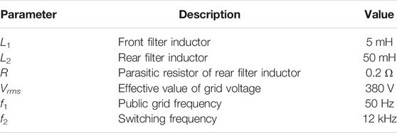
In this section, simulations have been carried out by using MATLAB/SIMULNK software. The experimental system is a three-phase dual-stage PV grid-tied inverter system, the maximum output power is 5.623 kW. The intensity of solar PV is 1,000 W/m2, the temperature is 25°C, both the BOOST circuit and the inverter use IGBT, and the modulation ratio is 0.95. Other system parameters are listed in Table 1.
Substitute the above parameters and take the internal model and proportional coefficient as follows:
Select Qk = diag(10 105) and Rk = 20 and then solve the optimal solution of Eq. 19, we get the following:
Select the low-pass filter:
Select Qo = 0.01, Ro = 1, ρ = 1012:
The system satisfies stability condition Theorem I; hence, the system is stable.
4.1 Normal Condition With Different Dead Time
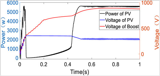
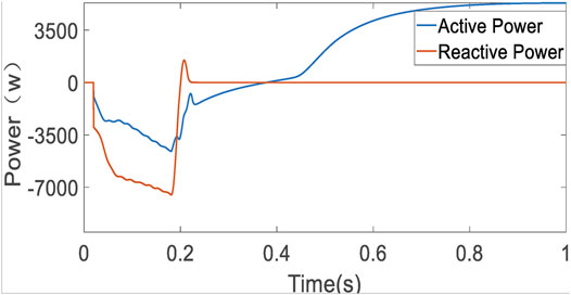
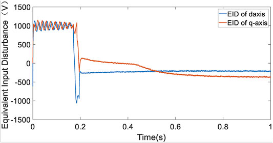
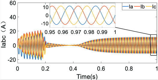
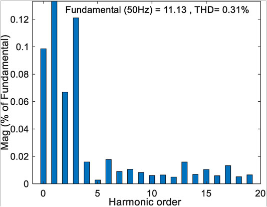
By employing EID-based control, Figure 6 shows that the system stabilizes quickly in normal condition, and the PV output power, output, and modulated dc voltage of the BOOST circuit basically stay the same, respectively. Figure 7 shows the active power and reactive power of grid-tied inverter output; the power factor in steady state is 1. Figure 8 presents the d- and q-axis disturbances estimation. It can be seen from Figure 6 that the PV output power is stable at about 0.8 s; so before 0.8 s, the disturbance caused by the voltage fluctuation of the dc side of the inverter is also estimated by EID, as shown in Figure 8. After 0.8 s, the dc side voltage is stable, and there is no other external disturbance. At this time, the EID estimation in Figure 8 is mainly caused by the non-linear switch, unmodeled dynamic, coupling terms, and so on. Figure 9 shows the high sinusoidal degree grid-tied current waveform, whose THD value is only 0.31%, and its harmonic spectrum is shown in Figure 10.
Figure 11 summarizes the THD values of the grid-tied current under the different dead time, which compares with the grid voltage feedforward PI controller (Zammit et al., 2021) and the PI-RC controller (Li et al., 2020). The dead time of SPWM signal is set from 2 to 6 µs. In real situations, the dead time of SPWM signal is usually 20%∼50% of the switching cycle (Lai et al., 2021); so in this paper, the dead time of SPWM signal is set from 2 to 6 µs. As the dead time increases, the THD value greatly increases using the PI control and increases slightly using the PI-RC. However, by the proposed EID-based controller, the THD value is still less than 2% and tends to be flat. Clearly, the EID-based controller is much better to inhibit the dead time effect.
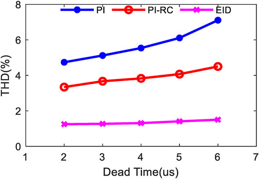
FIGURE 11. Comparative simulation results of THDs of the grid-tied current with different control methods under the different dead time.
4.2 Grid Voltage Distortion With Dead Time Effect
In addition, the inverter system under the different control strategies is tested when the grid voltage distortion is occurred at 0.8 s. The grid voltage contains 0.05 pu 3rd and 0.03 pu 5th harmonics (Lai et al., 2021), and the dead time is set as 5 µs.
Figure 12A shows the compressive grid-tied current harmonic spectrum among the PI, PI-RC, and proposed EID-based controllers, and Figure 12B shows the disturbance estimation of the proposed controller. The detailed data of Figure 12A are listed in Table 2. Figure 13 shows the three-phase grid-tied current waveforms by the different controller, respectively.
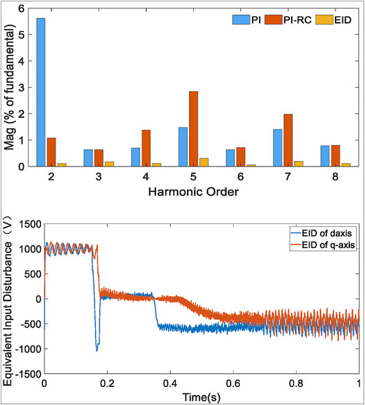
FIGURE 12. The experimental results with grid voltage distortion: (A) Harmonic spectrum comparison of current under the different methods; (B) Disturbance estimation of the EID method.

FIGURE 13. Comparative experimental results with different control methods of inverter under 5th and 7th harmonics of grid voltage: (A) PI method, (B) PI-RC method, and (C) EID method.
When non-ideal grid voltage and dead time effect occur simultaneously in system, the current distorts seriously by PI controller, and the THD value reaches 6.25%. It mainly contains low-order harmonics as shown in Table 2. Clearly, the steady-state performance is much better by PI-RC controller, its THD value is 4.5%. Figure 12B shows that the periodic disturbance is estimated quickly by proposed controller, all order current harmonics almost have been reduced as shown in Figure 12A, and the THD value is only 1.4%. Moreover, compared with the results in Figure 13A and Figure 13B, the three phases have the same amplitude in Figure 13C. Obviously, because the coupling term of the model will lead to cross coupling of dq axis current, the three-phase current under PI and PI-RC controller is unbalanced, but the three-phase current amplitude of the controller proposed in this paper is still the same, which implies that the proposed controller has an excellent model decouple capability.
Overall, the inverter system with the EID-based controller suppresses both dead time effect and grid voltage distortion satisfactorily. It is clear that the proposed current controller is better than others.
5 Conclusion
In this paper, an EID-based current control strategy is proposed to damp dead time effect for the three-phase dual-stage PV grid-tied inverter system, and its design and implementation are carried out. The proposed current controller is composed of five parts: gain module, internal model, state feedback controller, state observer, and EID estimator. In addition, its stability has been proved. First of all, the inverter model is modified by regarding the grid-tied inverter model coupling terms, uncertainties, unknown disturbances caused by dead time effect, and other uncertain disturbances as an unknown lumped disturbance. Next, the influence of the unknown lumped disturbance on the input channel without requiring prior information of above disturbances is estimated. Last, an equivalent control signal on the input channel to compensate the influence of the unknown lumped disturbance is produced. Compared with the grid voltage feedforward PI and PI-RC controllers, the results demonstrate that the proposed current controller could provide a better model decouple capability and more satisfactory grid-tied current quality, even under different dead time and grid voltage distortion.
Data Availability Statement
The original contributions presented in the study are included in the article/Supplementary Material; further inquiries can be directed to the corresponding author.
Author Contributions
FL and QL conducted the background research of the project. ZF completed the main theory and simulation content. FL and ZF completed the writing of the paper. The work was supported by the fund of FL and RZ.
Funding
This work is supported by the National Natural Science Foundation of China (no. 61673398), the Natural Science Foundation of Hunan Province (no. 2020JJ 2045), and Key Research and Development Program of Hunan Province (no. 2020WK 2007).
Conflict of Interest
The authors declare that the research was conducted in the absence of any commercial or financial relationships that could be construed as a potential conflict of interest.
Publisher’s Note
All claims expressed in this article are solely those of the authors and do not necessarily represent those of their affiliated organizations or those of the publisher, the editors, and the reviewers. Any product that may be evaluated in this article, or claim that may be made by its manufacturer, is not guaranteed or endorsed by the publisher.
References
Anderson, B. D., and Moore, J. B. (2007). Optimal Control: Linear Quadratic Methods. orth Chelmsford, MA: Courier Corporation.
Bag, A., Subudhi, B., Subudhi, B., and Ray, P. K. (2018). An Adaptive Sliding Mode Control Scheme for Grid Integration of a Pv System. Cpss Tpea 3, 362–371. doi:10.24295/CPSSTPEA.2018.00035
Cao, Y., Zhao, Q., Ye, Y., and Xiong, Y. (2020). Adrc-based Current Control for Grid-Tied Inverters: Design, Analysis, and Verification. IEEE Trans. Ind. Electron. 67, 8428–8437. doi:10.1109/TIE.2019.2949513
Chen, X., Ruan, X., Yang, D., Zhao, W., and Jia, L. (2018). Injected Grid Current Quality Improvement for a Voltage-Controlled Grid-Connected Inverter. IEEE Trans. Power Electron. 33, 1247–1258. doi:10.1109/TPEL.2017.2678525
Du, Y., Cao, W., She, J., Wu, M., Fang, M., and Kawata, S. (2021). Disturbance Rejection and Robustness of Improved Equivalent-Input-Disturbance-Based System. IEEE Trans. Cybern. 1–10. doi:10.1109/TCYB.2021.3053597
Errouissi, R., and Al-Durra, A. (2018). Design of Pi Controller Together with Active Damping for Grid-Tied Lcl-Filter Systems Using Disturbance-Observer-Based Control Approach. IEEE Trans. Ind. Applicat. 54, 3820–3831. doi:10.1109/TIA.2018.2823258
Errouissi, R., and Al-Durra, A. (2019). Disturbance-observer-based Control for Dual-Stage Grid-Tied Photovoltaic System under Unbalanced Grid Voltages. IEEE Trans. Ind. Electron. 66, 8925–8936. doi:10.1109/TIE.2018.2880141
Errouissi, R., Shareef, H., and Awwad, F. (2021). Disturbance Observer-Based Control for Three-phase Grid-Tied Inverter with Lcl Filter. IEEE Trans. Ind. Applicat. 57, 5411–5424. doi:10.1109/TIA.2021.3088391
Hu, J., Zhu, J., and Dorrell, D. G. (2015). Model Predictive Control of Grid-Connected Inverters for Pv Systems with Flexible Power Regulation and Switching Frequency Reduction. IEEE Trans. Ind. Applicat. 51, 587–594. doi:10.1109/TIA.2014.2328785
Lai, J., Yin, X., Yin, X., and Jiang, L. (2021). Fractional Order Harmonic Disturbance Observer Control for Three-phase Lcl-type Inverter. Control. Eng. Pract. 107, 104697. doi:10.1016/j.conengprac.2020.104697
Li, S., Chen, W., Fang, B., and Zhang, D. (2020). A Strategy of PI + Repetitive Control for LCL-type Photovoltaic Inverters. Soft Comput. 24, 15693–15699. doi:10.1007/s00500-020-04898-5
Liu, W., Hao, X., Yang, X., Zhao, M., Liu, T., and Huang, L. (2013). “A Multi-Resonant Sliding-Mode Controller for Single-phase Grid-Connected Inverter with Lcl-Filter,” in 2013 Twenty-Eighth Annual IEEE Applied Power Electronics Conference and Exposition (APEC), Long Beach, CA, March 17–21, 2013, 2541–2546. doi:10.1109/APEC.2013.6520653
Miyamoto, K., She, J., Imani, J., Xin, X., and Sato, D. (2016). Equivalent-input-disturbance Approach to Active Structural Control for Seismically Excited Buildings. Eng. Structures 125, 392–399. doi:10.1016/j.engstruct.2016.07.028
Sebaaly, F., Vahedi, H., Kanaan, H. Y., and Al-Haddad, K. (2018). Novel Current Controller Based on Mpc with Fixed Switching Frequency Operation for a Grid-Tied Inverter. IEEE Trans. Ind. Electron. 65, 6198–6205. doi:10.1109/TIE.2017.2784400
Wang, Y., Ren, B., and Zhong, Q.-C. (2016). Robust Power Flow Control of Grid-Connected Inverters. IEEE Trans. Ind. Electron. 63, 6887–6897. doi:10.1109/TIE.2016.2586439
Wu, Y., Ye, Y., Zhao, Q., Cao, Y., and Xiong, Y. (2020). Discrete-Time Modified UDE-Based Current Control for $LCL$-Type Grid-Tied Inverters. IEEE Trans. Ind. Electron. 67, 2143–2154. doi:10.1109/TIE.2019.2902829
Xiao, H. (2021). Overview of Transformerless Photovoltaic Grid-Connected Inverters. IEEE Trans. Power Electron. 36, 533–548. doi:10.1109/TPEL.2020.3003721
Xie, C., Liu, D., Li, K., Zou, J., Zhou, K., and M. Guerrero, J. J. (2021). Passivity-Based Design of Repetitive Controller for $LCL$-Type Grid-Connected Inverters Suitable for Microgrid Applications. IEEE Trans. Power Electron. 36, 2420–2431. doi:10.1109/TPEL.2020.3014365
Yang, Y., Zhou, K., and Blaabjerg, F. (2016). Current Harmonics from Single-phase Grid-Connected Inverters-Examination and Suppression. IEEE J. Emerg. Sel. Top. Power Electron. 4, 221–233. doi:10.1109/JESTPE.2015.2504845
Ye, Y., and Xiong, Y. (2018). UDE-based Current Control Strategy forLCCL-type Grid-Tied Inverters. IEEE Trans. Ind. Electron. 65, 4061–4069. doi:10.1109/TIE.2017.2760850
Yu, Y., and Hu, X. (2019). Active Disturbance Rejection Control Strategy for Grid-Connected Photovoltaic Inverter Based on Virtual Synchronous Generator. IEEE Access 7, 17328–17336. doi:10.1109/ACCESS.2019.2894786
Keywords: three-phase dual-stage photovoltaic (PV) grid-tied inverter system, dead time effect, equivalent input disturbance (EID), model decoupling, disturbance suppression
Citation: Liu F, Fan Z, Liu Q and Zou R (2021) Equivalent Input Disturbance-Based Control Design for Three Phase Dual-Stage Grid-Tied Photovoltaic System Considering Dead Time Effect. Front. Energy Res. 9:775437. doi: 10.3389/fenrg.2021.775437
Received: 14 September 2021; Accepted: 05 November 2021;
Published: 17 December 2021.
Edited by:
Sheng Huang, Hunan University, ChinaReviewed by:
Aravind C. K, Mepco Schlenk Engineering College, IndiaRui Wang, Northeastern University, China
Liao Wu, Hunan University, China
Copyright © 2021 Liu, Fan, Liu and Zou. This is an open-access article distributed under the terms of the Creative Commons Attribution License (CC BY). The use, distribution or reproduction in other forums is permitted, provided the original author(s) and the copyright owner(s) are credited and that the original publication in this journal is cited, in accordance with accepted academic practice. No use, distribution or reproduction is permitted which does not comply with these terms.
*Correspondence: Qianyi Liu, bGxpdTd5QGZveG1haWwuY29t
 Fang Liu
 Zhen Fan
 Qianyi Liu
 Runmin Zou