Corrigendum: Transient Heat Transfer Characteristics of Twisted Structure Heated by Exponential Heat Flux
 Li Wang*
 Qiusheng Liu
- School of Mechanical Engineering, Nantong University, Nantong, China
This study was conducted to investigate the transient heat transfer characteristics of a twisted structure. The twisted structure was heated according to exponential function (
1 Introduction
Heat transfer enhancement technology is of great importance in industries, such as power generation industry, chemical industry, and automotive. Researchers have been committed to increase heat transfer coefficients in all types of heat exchange equipment. Detailed surveys of enhancement techniques have been made by Patil and Farkade (2016), Menni et al. (2019), Suri et al. (2018), etc. Among all these techniques, twisted tape can change the flow pattern in a channel, reduce thickness of the boundary layer, and increase the heat transfer area. Thus, many research studies focused on the flow, and heat transfer characteristics for tube with twisted inserts have been carried out.
Manglik and Bergles (1993a) and Manglik and Bergles (1993b) obtained empirical correlations from wide experimental conditions for isothermal tubes with twisted tape as inserts. Saha et al. (2001) conducted experimental study for regularly spaced twisted tape–induced laminar tube flow with uniform heat flux (UHF), and the effect of tape width was discussed. Man et al. (2017) experimentally studied the heat transfer and friction characteristics of dual-pipe heat exchanger with alternation of clockwise and counterclockwise twisted tape. They suggest that this shape of twisted tape has an advantage in heat transfer enhancement over the typical twisted tapes. Kumar and Layek. (2018) studied the effect of twisted rib over the absorber plate of solar air heater with a maximum enhancement for heat propagation and friction factor to be 2.58 and 1.78 times that of smooth surface, respectively. Ponnada et al. (2019) compared the thermal performance of a circular tube with twisted tapes, perforated twisted tapes, and perforated twisted tapes with alternate axis. Most of the works deal with tubes or ducts with twisted tape as inserts and study the heat transfer enhancement effect with uniform wall temperature (UWT) or UHF boundary conditions. Few studies have focused on the twisted plate itself.
Forced convection process with transient heating boundary is much more complex than the UWT or UHF boundary conditions due to the thermal response behavior in the thermal boundary layer. Cess (1961), Riley (1963), and Cotta and Özişik (1986) analytically studied the thermal response of an unsteady laminar boundary layer on a flat plate due to step changes in wall temperature and wall heat flux. These studies have been made for the case in which the velocity field is independent of time. The solution of energy equation generally adopts the energy integral equation or use similarity variables to reduce the mathematical difficulties. Khaled (2012) compared the heat transfer enhancement in laminar channel flow with four kinds of heat flux distributions: periodic step, periodic sinusoidal, linear, and exponential distribution. It was found that the maximum heating source excess temperature for the case with exponential heat flux is at most of about 22.4% lower than that with UHF over the boundary. This work proves that, with a proper heat flux distribution, additional heat can be transferred under same maximum temperatures. Hata and Masuzaki (2011) studied the tube flow with twisted tape as inserts. Exponentially increasing heat generation rate was added to the tube, and the transient heat transfer coefficient of the tube was analyzed. In our previous research, Liu et al. (2008), Liu et al. (2014), and Liu et al. (2017) experimentally studied the transient heat transfer process for parallel flow of helium gas over a horizontal cylinder and a flat plate. An exponential increasing heat generation rate was applied for the transient heating condition. The flow and heat transfer parameters on transient heat transfer were investigated under wide experimental conditions.
This study is aimed to investigate the transient heat transfer phenomena of a twisted plate. Exponentially increasing heat generation rate (
2 Experimental Study
2.1 Experimental Apparatus
The experimental apparatus consisted of gas cylinder (1), compressor (2), surge tanks (3) (9), preheater (6), cooler (8), vacuum pump (10), and the test section (7), as shown in Figure 1 (Liu et al., 2014). The flow direction of the coolant (helium gas) is shown by arrows. A vacuum pump was used to degas the main flow loop and other branches. Helium gas was circulated by a compressor, and the fluctuations of gas flowing and pressure caused by compressor were removed with the high-capacity surge tanks that are set at both inlet and outlet of the compressor. The helium gas inside the loop was cooled by a cooler after the exit of the test section. A preheater was set before the gas flows into the test section to ensure the inlet temperature. The flow rate in the test section was measured with the turbine meter, and the system pressure was measured with a pressure transducer. The temperature of the gas at the exit of turbine flow meter and in the test section was measured by K-type thermocouples with a precision of ±1 K.
FIGURE 1
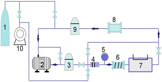
FIGURE 1. Schematic diagram of experimental apparatus: 1) gas cylinder; 2) compressor; 3) delivery surge tank; 4) filter; 5) turbine flow meter; 6) preheater; 7) test section; 8) cooler; 9) surge tank; and 10) vacuum pump.
The test heater was mounted horizontally along the center axis of the circular test channel, which is made of stainless steel with inside diameter of 20 mm, as shown in Figure 2 (Liu et al., 2014). A twisted tape with five pitches (each was 180° twisted with 20 mm in length) was used in the experiment. It was made from a platinum plate with thickness of 0.1 mm and width of 4 mm. The ends of twisted tape were connected to two copper plates and then connected to two copper electrodes. Two fine platinum wires (50 μm in diameter) were spot welded to the end parts of the twisted plate as potential conductors. The length between the potential taps is defined as the effective length on which transient heat transfer was measured.
FIGURE 2
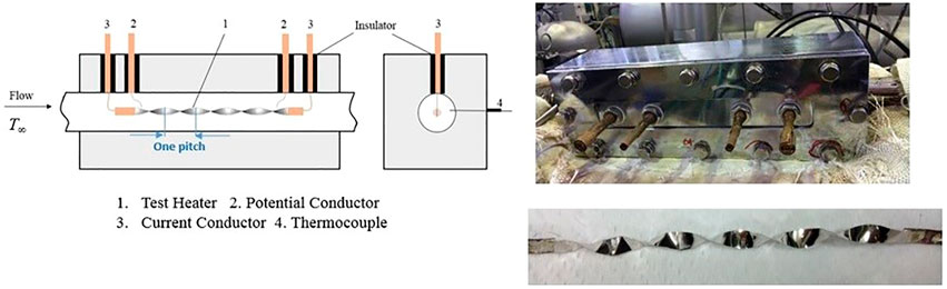
FIGURE 2. The test section: 1) test heater; 2) potential conductor; 3) current conductor; 4) thermocouple.
The twisted plate was heated by the direct current from a power source. The heat generation rate of the plate was controlled and measured by electrical control and measurement circuit. A total of four parts, namely, the double bridge circuit, the electrical control and feedback part, the signal input part, and the output data processing part, were built with connections. The double bridge circuit (also called Kelvin bridge or Kelvin double bridge) was applied to measure the resistance of the test heater to obtain the average temperature of the test heater on the basis of a calibrated temperature-resistance correlation. A high-speed analog computer was applied in part 2 to support a rapid and precise calculation-feedback process for the heat generation and heater temperature control. While the signal input and output data processing were fulfilled with a personal computer (PC) (Figure 3) (Liu et al., 2014).
FIGURE 3
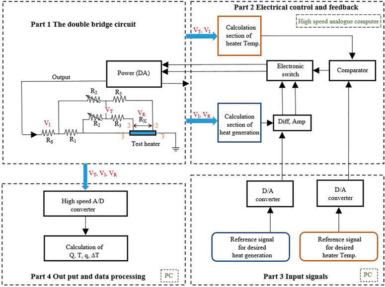
FIGURE 3. Electrical control and measurement circuit.
2.2 Experimental Method and Procedure
The experiment was conducted with the following procedure.
Before the twisted plate was installed into the test section, a calibration for temperature-resistance correlation was completed in a thermostat, with the calibration range for room temperature of up to 150°C. A calibrated correlation for the test heater was obtained.
Next, the test heater was installed horizontally along the axis of the test section with both ends connected to two copper plates and then connected to the double bridge branch. Two fine platinum wires (50 μm in diameter) were spot welded close to the end parts of the twisted plate as potential conductors and then connected to the double bridge branch.
Then, the helium gas (99.9% purity) was filled to the test loop and maintained at a certain pressure after the test loop being degassed by a vacuum pump. A piston compressor was used to circulate the flow in the test loop. There are two bypass branches for the test loop: one is parallel to the test section and the other goes side by side with the compressor. By adjusting the two bypass valves in the bypass branches, the flow rate could be sequentially lowered from the maximum flow rate to the desired values.
After the pressure and flow rate were confirmed to be stable at desired value in the loop, the electric current was supplied to the test heater with exponentially increasing heat generation rate controlled by the electrical control circuit. Meanwhile, the heat flux and the heater surface temperature were measured.
The uncertainties of the measurements of the heat generation rate, the heat flux of the test heater, and the heater surface temperature are estimated to be ±1%, ±2%, and ±1 K, respectively (Liu et al., 2008).
The heat flux of the heater is calculated by the following equation:
where ρh, ch, and δ are the density, specific heat, and thickness of the test heater, respectively.
The instantaneous surface temperature of test heater was calculated by the following equation assuming that the surface temperature of test heater is uniform:
Equation 2 is an unsteady heat conduction equation, which was used to calculate instantaneous surface temperature of the test heater by assuming the surface temperature around the test heater to be uniform. Boundary conditions are as follows:
where α and λ are the thermal diffusivity and thermal conductivity, respectively. Ta is average temperature of the heater.
Experimental conditions are shown in Table 1. The twist tape has five pitches (each pitch is 180° twisted with 20 mm in length). The actual length of the twist tape is 106.4 mm, which is used in the experiment test due to manufacturing error. The inlet temperature of coolant gas (helium) is 298 K under a system pressure of 500 kPa. The flow velocity ranged from 4 to 10 m/s, and the corresponding Reynolds numbers ranged from 8 × 10³ to 2.5 × 10⁴. The heat generation rate was raised with exponential function.
TABLE 1
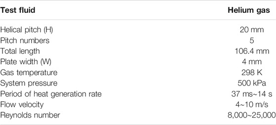
TABLE 1. Experimental conditions.
3 Experimental Results
Figure 4 shows the experimental data of heat generation rate applied to the twisted plate. A total of 10 periods of heat generation rate τ were adopted ranging from 37 to 14,034 ms. As can be seen from the figure, the heat generation rate increases exponentially although some fluctuations occur at the beginning of the transient heating process. This is due to the inevitable oscillating of the electrical control circuit. For this reason, we used the data after the heat generation curve is stable in this research.
FIGURE 4
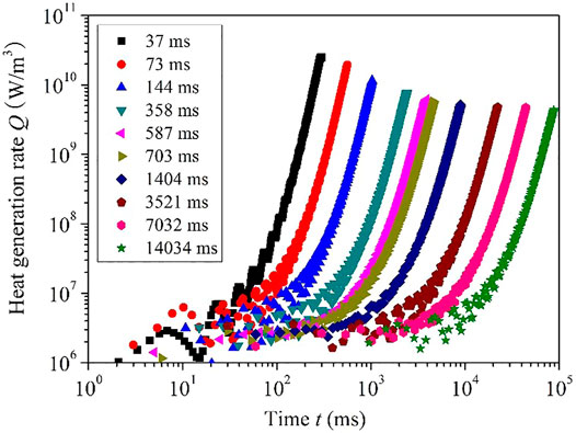
FIGURE 4. The exponential heat generation rate for the twisted plate with various heat generation periods.
As can be seen in Figure 5, the average surface temperature increases exponentially as the heat generation rate increases in exponential function. By fitting the curves with an exponential function, C is a coefficient to be fitted,
FIGURE 5
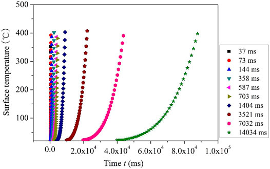
FIGURE 5. The average surface temperature of the twisted plate at various heat generation periods.
The surface heat transfer coefficient of the twisted plate, h, is defined as follows:
where q is the heat flux of the heater, which can be calculated according to Eq. 1; ΔT is the surface temperature difference of the twisted plate, which is defined as the difference between the average surface temperature of the twisted plate
Transient heat transfer coefficient at various heat generation periods of 37, 73, 144, and 358 ms is shown in Figure 6. The flow velocity of helium gas is 4 m/s. Transient heat transfer coefficient decreases to quasi-steady value after several t/τ. With a smaller τ, the transient heat transfer coefficient is larger in both the initial decreasing region and the quasi-steady region. The quasi-steady value of transient heat transfer coefficient is defined as hqs.
FIGURE 6

FIGURE 6. Transient heat transfer coefficient at various heat generation periods.
The quasi-steady heat transfer coefficients at various heat generation periods and flow velocities are shown in Figure 7. As can be found in the figure, hqs increases with the increase of flow velocity. The increasing rate at lower velocities is higher than that at higher velocities. The main reason for this is that, for higher velocities, the convective heat transfer plays a dominant role and the effect of heat conduction is of less importance than that for lower velocities. The quasi-steady heat transfer coefficient approaches asymptotic value at each velocity when τ is longer than about 1 s. On the other hand, when the period τ is shorter than about 1 s, hqs increases as τ shortens. When the period is relatively short, it means that the increasing rate of the heat generation rate and the surface temperature is relatively high. With fast increasing boundary temperature, the temperature gradient of the fluid in the near-wall region becomes larger compared to steady state heat transfer process, which results in a larger heat transfer coefficient. Therefore, during the transient process, temperature distribution in the thermal boundary is different compared to UWT or UHF boundary conditions. When period τ is larger than about 1s, the instantaneous changes in the thermal boundary become less prominent. The heat transfer process is similar to normal UWT or UHF conditions.
FIGURE 7
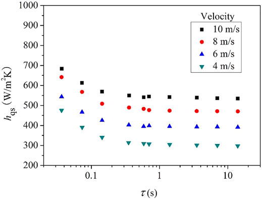
FIGURE 7. Quasi-steady heat transfer coefficient at various heat generation periods and velocities.
The Nusselt number of the twisted plate at steady state (periods ranging from 1.4 to 14 s) with flow velocity ranging from 4 to 10 m/s was compared with published empirical correlations, as the laminar analytical solution for plate (Holman, 2010), the Manglik and Bergles (1993a) correlation for tube flow with twisted tape insert, and the Dittus-Boelter correlation for tube flow (Faghri et al., 2010).
As shown in Figure 8, by comparing the Nu for the twisted plate with flat plate, it is about 3.2 times higher at Reynolds number of 15,000. With the increase of Re, the twisted plate shows even better performance. For tube flows without any inserts as the Dittus-Boelter correlation shows, the Nu is the lowest. The experimental data for twisted plate is about 5.2 times of the tube flow at Reynolds number of 15,000. When we compare the experimental data with Manglik and Bergles correlation, the Nusselt number is about twice the value. This is because the experimental result for Nu in this study is for the twisted plate itself, whereas in the Manglik and Bergles correlation, the Nu is for the tube with twisted plate as inserts. The Manglik and Bergles correlation was obtained for Re ranged from 300 to 30,000. The twist ratio y (y = H/W, where H is 180° twist pitch and W is width) is 3–6.
FIGURE 8
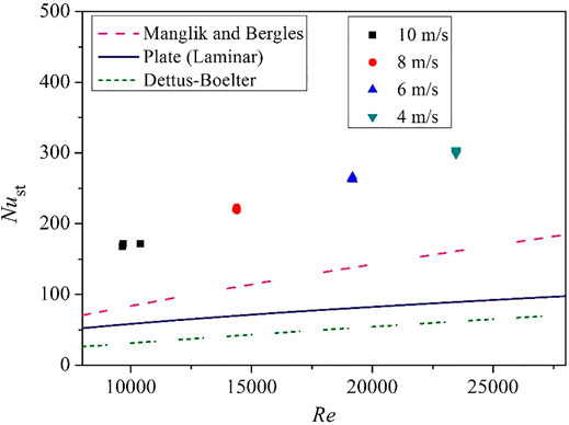
FIGURE 8. Comparison of experimental data with published correlations.
4 Response Analysis for Heat Transfer Interface of Solid and Fluid Area
To help understand the heat transfer response for transient heat transfer process, we now carry out a simple analysis for fluid-solid coupled transient heat transfer procedure. A near-wall point in the fluid domain is set as point F, and a near-wall point in the solid domain is set as point S, as shown in Figure 9. During the transient process, physical parameters such as temperature and conductivity vary with time, so as the variables at the interface (wall surface). Taking a simple finite difference to approximate the heat fluxes for both sides, we then have a discrete form of the physical heat flux and temperature continuity across the interface.
FIGURE 9
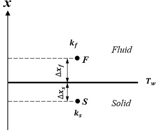
FIGURE 9. Temperature variations at fluid-solid interface.
The wall temperature can thus be represented in terms of updated Tf and Ts.
A linear correlation will be obtained for Tw, when assuming the thermal conductivities for fluid (kf) and solid (ks) as constant. Instantaneous wall temperature can be expressed as follows:
where
The key to the accuracy and consistency of the wall temperature fluctuation value
The time scale
For this research with exponential increasing heat input, it is considered that, with a fixed Pr, the increasing rate of heat generation rate is the main effect that affects the quasi-steady heat transfer coefficient. On the basis of all these research studies, we would like to take
According to our early research, it is observed that the transition point of period τ for heat transfer coefficient does not show much dependence on velocity because we have rose up the flow velocity to 150 m/s in a narrow channel (Liu et al., 2017). Besides, the effects of gas pressure, initial gas temperature, initial heat generation rate, and structure of the heating surface on transition point are not obvious according to this research and our wide range experiments (Liu et al., 2008; Liu et al., 2014; Liu et al., 2017). Early research by Chao and Cheema (1967) indicated that the response time of the thermal layer due to a step change in wall flux varies directly as Pr1/3 with Pr ranged from 0.72 to 100. The research by Khaled (2012) also suggested that the monotonic heat flux increase effect tends to increase the heat transfer coefficient due to the associated increase in the temperature difference near boundary. However, the heat flux discussed in this research is spatial dependent, not time dependent.
5 Conclusion
Forced convection transient heat transfer for helium gas flowing over a twisted plate with exponential increasing heat input was experimentally studied. The following conclusions were obtained.
1) Surface temperature difference increases exponentially with the same period as the heat generation rate increases with exponential function.
2) The heat transfer coefficient approaches the quasi-steady state one after a large enough heat generation period of about 1 s, and it becomes higher for a small period less than about 1 s.
3) It is estimated that, when the increasing rate of heat generation rate is high enough
4) The heat transfer enhancement characteristics were discussed with penetration depth.
Data Availability Statement
The original contributions presented in the study are included in the article/supplementary material; further inquiries can be directed to the corresponding author.
Author Contributions
LW contributed to the conception of the study, collected the experiment data, performed the analysis, and wrote the manuscript. QL has contributed to experimental apparatus and paper instructions.
Funding
This research work is supported by Nantong Science and Technology Plan Project (JC2020145).
Conflict of Interest
The author declares that the research was conducted in the absence of any commercial or financial relationships that could be construed as a potential conflict of interest.
Publisher’s Note
All claims expressed in this article are solely those of the authors and do not necessarily represent those of their affiliated organizations or those of the publisher, the editors, and the reviewers. Any product that may be evaluated in this article, or claim that may be made by its manufacturer, is not guaranteed or endorsed by the publisher.
Acknowledgments
The experiment work in this paper was done in Graduate School of Marine Engineering, Kobe University, Japan. We would like to thank for the support by the Japan Society for the Promotion of Science (JSPS) (Grant-in Aid for Scientific Research (C), KAKENHI, No. 15K05829).
Abbreviations
ch, specific heat of test heater [J/(kg∙K)]; cp, specific heat of helium gas [J/(kg∙K)]; D, diameter of the circular channel [m]; g, gravitational acceleration [m/s2]; h, heat transfer coefficient [W/(m2∙K)]; k, thermal conductivity [W/(m∙K)]; p, static pressure [Pa]; Pr, Prantl number; Q, heat generation rate per unit volume [W/m3]; Q0, initial heat generation rate [W/m3]; q, heat flux [W/m2]; T, temperature [K]; Ta, average temperature of the heater [K]; Tf, fluid temperature at point F [K]; Ts, temperature of the solid tape at point S [K]; Twa, average temperature of wall surface [K]; ΔT, temperature difference,
References
Cess, R. D. (1961). Heat Transfer to Laminar Flow across a Flat Plate with a Nonsteady Surface Temperature. Trans. ASME 83 (3), 274–279. doi:10.1115/1.3682256
Chao, B. T., and Cheema, L. S. (1967). Unsteady Heat Transfer in Laminar Boundary Layer over a Flat Plate. Int. J. Heat Mass Transfer 11, 1311–1324. doi:10.1016/0017-9310(68)90177-4
Cotta, R. M., and Özişik, M. N. (1986). Transient Forced Convection in Laminar Channel Flow with Stepwise Variations of wall Temperature. Can. J. Chem. Eng. 64, 734–742. doi:10.1002/cjce.5450640504
Dittus, F. W., and Boelter, L. M. K. (1985). Heat Transfer in Automobile Radiators of the Tubular Type. Int. Commun. Heat Mass Transfer 12, 3–22. doi:10.1016/0735-1933(85)90003-x
Faghri, A., Zhang, Y., and Howell, J. (2010). Advanced Heat and Mass Transfer. Columbia, United States: Global Digital Press. 978-0-9842760-0-4.
Hata, K., and Masuzaki, S. (2011). Twisted-tape-induced Swirl Flow Heat Transfer and Pressure Drop in a Short Circular Tube under Velocities Controlled. Nucl. Eng. Des. 241 (No.11), 4434–4444. doi:10.1016/j.nucengdes.2010.09.023
Khaled, A. (2012). Heat Transfer Enhancement Due to Properly Managing the Distribution of the Heat Flux: Exact Solutions. Energ. Convers. Manag. 53 (1), 247–258. doi:10.1016/j.enconman.2011.09.004
Kumar, A., and Layek, A. (2018). Thermo-hydraulic Performance of Solar Air Heater Having Twisted Rib over the Absorber Plate. Int. J. Therm. Sci. 133, 181–195. doi:10.1016/j.ijthermalsci.2018.07.026
Liu, Q. S., Shibahara, M., and Fukuda, K. (2008). Transient Heat Transfer for Forced Convection Flow of Helium Gas over a Horizontal Plate. Exp. Heat Transfer 21, 206–219. doi:10.1080/08916150802072859
Liu, Q., Wang, L., Mitsuishi, A., Shibahara, M., and Fukuda, K. (2017). Transient Heat Transfer for Helium Gas Flowing over a Horizontal cylinder in a Narrow Channel. Exp. Heat transfer 30 (4), 341–354. doi:10.1080/08916152.2017.1283373
Liu, Q., Zhao, Z., and Fukuda, K. (2014). Transient Heat Transfer for Forced Flow of Helium Gas along a Horizontal Plate with Different Widths. Int. J. Heat Mass Transfer 75, 433–441. doi:10.1016/j.ijheatmasstransfer.2014.03.077
Man, C., Lv, X., Hu, J., Sun, P., and Tang, Y. (2017). Experimental Study on Effect of Heat Transfer Enhancement for Single-phase Forced Convective Flow with Twisted Tape Inserts. Int. J. Heat Mass Transfer 106, 877–883. doi:10.1016/j.ijheatmasstransfer.2016.10.026
Manglik, R. M., and Bergles, A. E. (1993). Heat Transfer and Pressure Drop Correlations for Twisted-Tape Inserts in Isothermal Tubes: Part I-Laminar Flows. J. Heat Transfer 115, 881–889. doi:10.1115/1.2911383
Manglik, R. M., and Bergles, A. E. (1993). Heat Transfer and Pressure Drop Correlations for Twisted-Tape Inserts in Isothermal Tubes: Part II-Transition and Turbulent Flows. J. Heat Transfer 115, 890–896. doi:10.1115/1.2911384
Menni, Y., Azzi, A., and Chamkha, A. (2019). Enhancement of Convective Heat Transfer in Smooth Air Channels with wall-mounted Obstacles in the Flow Path. J. Therm. Anal. Calorim. 135, 1951–1976. doi:10.1007/s10973-018-7268-x
Patil, M. R., and Farkade, H. S. (2016). Review of Heat Transfer Enhancement Techniques in Circular Tube. Discov. Eng. 4 (12), 1–7. doi:10.1155/2014/250354
Ponnada, S., Subrahmanyam, T., and Naidu, S. V. (2019). A Comparative Study on the thermal Performance of Water in a Circular Tube with Twisted tapes, Perforated Twisted tapes and Perforated Twisted tapes with Alternate axis. Int. J. Therm. Sci. 136, 530–538. doi:10.1016/j.ijthermalsci.2018.11.008
Riley, N. (1963). Unsteady Heat Transfer for Flow over a Flat Plate. J. Fluid Mech. 17 (1), 97–104. doi:10.1017/s0022112063001130
Saha, S. K., Dutta, A., and Dhal, S. K. (2001). Friction and Heat Transfer Characteristics of Laminar Swirl Flow through a Circular Tube Fitted with Regularly Spaced Twisted-Tape Elements. Int. J. Heat Mass Transfer 44, 4211–4223. doi:10.1016/s0017-9310(01)00077-1
Keywords: exponential heat flux, twisted plate, transient heat transfer, forced convection, heat transfer enhancement
Citation: Wang L and Liu Q (2021) Transient Heat Transfer Characteristics of Twisted Structure Heated by Exponential Heat Flux. Front. Energy Res. 9:771900. doi: 10.3389/fenrg.2021.771900
Received: 07 September 2021; Accepted: 05 October 2021;
Published: 15 November 2021.
Edited by:
Xuewen Cao, China University of Petroleum (East China), ChinaReviewed by:
Qunqing Lin, Nanjing University of Science and Technology, ChinaWenlei Lian, Nanjing University of Aeronatics and Astronautics, China
Yantao Li, Dalian Maritime University, China
Copyright © 2021 Wang and Liu. This is an open-access article distributed under the terms of the Creative Commons Attribution License (CC BY). The use, distribution or reproduction in other forums is permitted, provided the original author(s) and the copyright owner(s) are credited and that the original publication in this journal is cited, in accordance with accepted academic practice. No use, distribution or reproduction is permitted which does not comply with these terms.
*Correspondence: Li Wang, wang1988@ntu.edu.cn