- Institute of Refrigeration and Cryogenics, Shanghai Jiao Tong University, Shanghai, China
Ammonia water absorption refrigeration systems are effective in utilizing fishing-boat exhaust waste heat for cryopreservation. However, the liquid level control and the use of a solution pump characterized by small flowrate and high-pressure head result in poor reliability in the traditional system. Besides, the system must necessarily be designed anti-swaying and anti-corrosion. This paper proposes a forced flow diffusion absorption refrigeration system, in which an inherently leak-free canned motor pump and an ejector are employed to provide the driving forces of the gas and liquid loops. The approximate single pressure operation allows for a simple passive liquid sealing control without throttling valves. The system adopts an integrated cooling strategy which allows the system to operate under swaying conditions, and the external seawater cooled heat exchanger avoids internal corrosion and leakage. The thermal analysis shows the system is valid to be operated under wide operating conditions, and the coupled gas and solution circulation ratios determined the performance of the novel system. There is an optimal ammonia mass fraction difference in the gas loop to obtain the optimal COP. The COP reaches 0.4 when the temperatures at the outlets of the generator, evaporator, absorber, and condenser are 160, −15, 35, and 35°C, respectively. The novel system provides a reliable absorption refrigeration system design for fishing-boat applications.
Introduction
Waste heat reuse is quite important to improve primary energy efficiency and thus the CO2 emission can be reduced effectively (Oluleye et al., 2017). The waste heat from diesel engines on fishing boats accounts for about 60% of the energy input, and it is removed in the form of exhaust and engine coolant. Meanwhile, cryopreservation on fishing boats is commonly achieved by compression refrigeration systems powered by diesel generators, which consume a significant amount of fuel. In actual fact, the exhaust may reach 400°C and even higher, and it can be utilized to power an absorption refrigeration system for cryopreservation. LiBr-H2O and NH3-H2O are normally employed as the working pairs in absorption systems, but only the latter is applicable for freezing applications (Du et al., 2017). However, there are three main drawbacks to be solved when modularized NH3-H2O absorption refrigeration systems with cooling capacities between 10 and 50 kW are to be applied on fishing boats. First, the reliability of the system is poor due to the liquid level control through throttling valves and sensors for preventing vapor short circuit between the generator and the absorber and flooding in the generator. This trouble is caused by the large internal operating pressure difference. Second, the solution pump, characterized as high pressure head (>1000 kPa) and low flowrate (<1m3 h−1), is less efficient and vulnerable to leaking, and normally, a reciprocation piston/diaphragm pump (Garimella et al., 2016; Jiménez-García and Rivera, 2019) or a multistage centrifugal pump (Yuan et al., 2018) is employed. Moreover, the solution pump is one of the most serious components threatening the normal operation of an ammonia-water absorption system (Lazzarin et al., 1996), and thus a reliable solution pump is important for the system. Third, the traditional design of falling film absorbers is not suitable for swaying conditions, and the internal cooling by seawater increases the risk of leakage. The three main drawbacks limit the application of the absorption refrigeration system on fishing boats, and it is of great significance to propose a reliable ammonia-water absorption refrigeration system. The author developed an ammonia-water absorption refrigeration prototype for diesel exhaust waste utilization (Du et al., 2017); however, the first and second drawbacks mentioned above limited our further experiment and application on fishing-boats even though the anti-swaying design of absorber was done.
As for the first and second drawbacks mentioned above, engineers generally focused on the development of reliable pumps, valves, and control units which incompletely solve the drawbacks and increases the cost of the system, while researchers generally ignored these problems, intentionally or unintentionally. It is necessary to solve the drawbacks from the perspective of thermodynamic system innovation. Diffusion absorption systems using equilibrium gas provided inspiration to solve the drawbacks. The partial pressure effect of the equilibrium gas in the evaporator can make the liquid ammonia obtain a lower partial pressure under the condition of constant total pressure so that the evaporation process can be accomplished without a throttling valve. The solution is circulated by a bubble pump based on the principle of thermosiphon (Aman et al., 2018), and both the gas and liquid loops are achieved by gravity. In this case, the liquid level control is passive and the system reliability can be improved. However, the cooling capacity of the diffusion absorption system is small, usually lower than 400 W (Rodríguez-Muñoz and Belman-Flores, 2014), restricted by the circulating flow rates of the gas and liquid. Since the gas and liquid flow naturally, the cooling capacity is very difficult to be expanded and the system would be bulky even though such a system could be implemented. Jakob et al. (2007) developed a water-cooled diffusion absorption prototype for air-conditioning with a cooling capacity of 2.5 kW, and the size is 0.6 × 0.6 × 2.2 m. Then, Yousfi et al. (2017) developed a hot water-driven diffusion absorption prototype with a cooling capacity of 5 kW, and the size is the same as the previous one. However, the developed prototypes were applicable for air-conditioning applications, and the cooling capacity would be significantly reduced if the prototypes were operated under freezing conditions. To increase the cooling capacity of the diffusion absorption system, parallel bubble pumps (Schmid et al., 2019) or a small leak-proof pump (Wang, 2012) can be employed to increase the circulated flow rate of the solution. Besides, a magnetic connecting propeller can be implemented to improve the circulated flow rate of gas (Schmid and Spindler, 2016). However, the cooling capacity is still small and how to enlarge the cooling capacity effectively is worthy of research.
As for the third drawback, mainly the anti-swaying design of the absorber, flowing restricted channels which can reduce free vapor-liquid surface can be applied such as plate channels (Cerezo et al., 2009; Triché et al., 2017), hollow fiber tubes (Chen et al., 2006), small diameter tube bundle units (Chen et al., 2021) and micro-channel units (Chandrasekaran et al., 2020). Additionally, adiabatic absorbers (Ventas et al., 2012; Liang et al., 2021) with solution spraying or sprinkling can be efficient for swaying conditions when the absorber is designed to be vertical and slender, and the potential heat capacity of the circulated solution is necessary to be large, i.e., a large precooling degree or a large circulated amount of the solution. An appropriate strategy should be applied based on the system design.
Several ammonia-based absorption refrigeration systems have been proposed for fishing-boat exhaust waste heat utilization. Salmi et al. (2017) investigated the feasibility of LiBr-H2O and NH3-H2O absorption refrigeration systems using the waste heat of a ship as an energy source in terms of thermodynamics. Palomba et al. (2017) theoretically studied the performance of adsorption and NH3-H2O absorption refrigeration systems for application on low emission fishing vessels. Ouadha and El-Gotni (2013) integrated an ammonia-water absorption refrigeration system with a marine diesel engine and investigated the feasibility on the basis of thermodynamics. Fernández-Seara et al. (1998) proposed an exhaust heat recovery system to power an onboard NH3-H2O absorption refrigeration plant in trawler chiller fishing vessels. Chen et al. (2010) proposed and theoretically analyzed an aqueous ammonia absorption refrigeration system driven by fishing boat diesel exhaust heat with the structure of a horizontal tube absorber and packing distillation column. Táboas et al. (2014) analyzed ammonia-water and ammonia-salt mixture absorption cycles for refrigeration purposes in fishing ships. Ezgi and Bayrak (2020) carried out an experimental analysis of a laboratory-scale diesel engine exhaust-heat driven NH3-H2O absorption refrigeration system as a model for naval surface ship applications. However, these studies were mainly focused on the feasibility of an ammonia absorption refrigeration system applied to ship waste heat recovery, and the requirements of an onboard ammonia-based absorption refrigeration system were not taken into full consideration, as well as the reliability of the system.
Therefore, to solve the three drawbacks mentioned above when an ammonia-water absorption refrigeration system is to be applied on fishing boats, we propose a novel forced flow diffusion absorption refrigeration system for 10–50 kW freezing applications in this paper. A thermal analysis is conducted to investigate the feasibility and features of the proposed system.
System Description
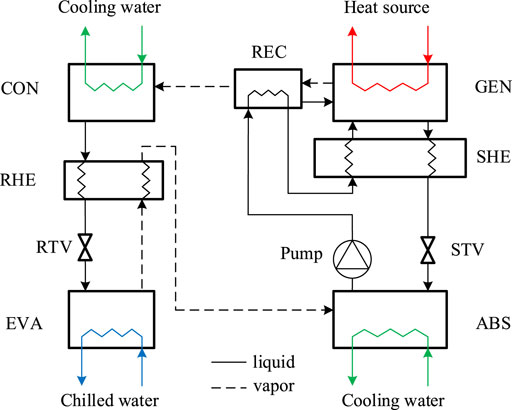
Before proposing the novel system, the principle of the traditional single-stage ammonia-water absorption system is briefly explained for basic understanding. As shown in Figure 1, the traditional system is considered to be composed of a solution loop and a refrigerant loop. Specifically, the solution loop consists of a generator (GEN), a rectifier (REC), an absorber (ABS), a solution heat exchanger (SHE), a solution throttling valve (STV), and a solution pump. Due to the thermodynamic characteristics of the ammonia-water solution under different temperature, pressure, and mass fraction conditions, the absorption in ABS and desorption in GEN achieves the suction and discharge of the refrigerant of ammonia, which is just like a mechanical compressor. The solution rich in ammonia is called the strong solution while that poor in ammonia is called the weak solution. The discharged vapor in GEN is impure due to the small partial pressure difference between ammonia and water, and the vapor is purified in REC. The rectification heat is removed by the circulated strong solution from ABS. SHE is used for solution heat recovery, and STV is used to regulate the flow rate of the weak solution and the liquid level in GEN to avoid a vapor short circuit between GEN and ABS and flooding in GEN. The refrigerant loop consists of a condenser (CON), a refrigerant heat exchanger (RHE), a refrigerant throttling valve (RTV), and an evaporator (EVA), just the same as those in a mechanical compression refrigeration system; the suction and discharge of the refrigerant achieved by the solution loop can be regarded as a part of the refrigerant loop. The heat is provided in GEN, and the cooling effect is produced in EVA. The heat output is achieved in CON and ABS, and both CON and ABS are needed to be cooled internally.
The temperature-pressure-mass fraction (P-T-x) diagram of the traditional single-stage ammonia-water absorption refrigeration system is shown in Figure 2. It can be found that the system is operated between the condensation pressure and the evaporation pressure, and the pressure difference is large due to the thermodynamic characteristics of ammonia under freezing operating conditions, usually larger than 1000 kPa. The solution pump has to deliver the solution with a large pressure head, and the streams between the high-pressure devices and the low-pressure devices have to be regulated by throttling valves. The vapor phase pressures of ammonia in EVA and ABS are identical because pure ammonia is evaporated and absorbed. It should be noted that the vertical coordinate indicates the partial pressure of ammonia in both gas and liquid phases, and thus there is a saturated pressure difference of the solution in and out of GEN, as well as that in and out of ABS.
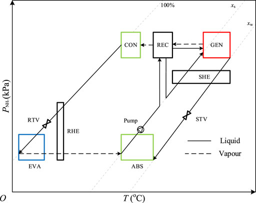
FIGURE 2. The P-T-x diagram of the traditional single-stage ammonia-water absorption refrigeration system.
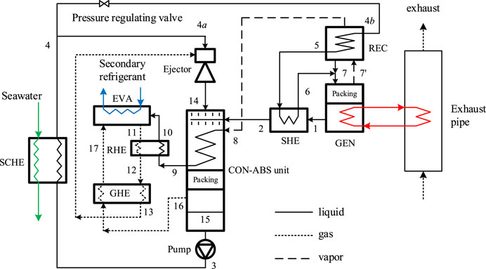
The schematic of the forced flow diffusion absorption refrigeration system is shown in Figure 3.
The novel system can be considered to be composed of four loops including the solution loop (1-2–15-3–4-4b-5-6-7–1), the refrigerant loop (8-9–10–11–12–13–14–15-3–4-4b-5-6–7′-8), the gas loop (16–17–11–12–13–14–16), and the recirculated solution loop (3-4-4a-14–15–3). In diffusion absorption systems, hydrogen (H2) and helium (He) are usually chosen to be the equilibrium gases due to their extremely low critical temperatures and their high diffusion coefficients in ammonia. Helium is determined in this system because of the lower specific heat capacity compared to hydrogen; moreover, helium is safer. During normal operation, helium exists and circulates in the gas loop which is composed of EVA, RHE, the gas heat exchanger (GHE), the ejector, and the condenser-absorber (CON-ABS) unit. The CON-ABS unit is the structure that the condenser coils are assembled in ABS, and both the condenser coils and the packing provide the mass transfer area for absorption. In Figure 3, the solid, dashed, and dotted lines represent the liquid (pure liquid ammonia, ammonia water solution), vapor (pure ammonia vapor, ammonia water vapor), and gas (vapor mixture of helium and ammonia) streams, respectively. In this paper, the mass fraction of ammonia in the liquid is defined as the ratio of the mass of ammonia in the liquid to the total mass of the liquid. So does the definition of the mass fraction of ammonia in the gas.
The operation can be described as follows: the strong solution at the outlet of the CON-ABS unit (15) is pumped to the seawater cooled heat exchanger (SCHE) where it is cooled by seawater (3–4). Then the strong solution is separated into two branches. One branch with a higher flow rate flows to the motive nozzle of the ejector (4-4a) and sucks the gas from EVA; before the suction, the gas has gone through RHE and GHE (11–12–13) in turn for preheating. Next, the ejector sprays the gas-liquid mixture into the CON-ABS unit (14). The weak solution from GEN is precooled in SHE (1–2) and fed to the CON-ABS unit, and then it is mixed with the sprayed liquid and falls on the surface of the condenser coils and the packing in the CON-ABS unit. The falling solution absorbs ammonia from the gas on the surface of the condenser coils while the ammonia vapor from REC is condensed in the condenser coils (8–9) at the same time. The absorption is further completed on the surface of the packing which provides a large area for mass transfer, and the heat released from the condensation and absorption processes raises the temperature of the falling solution. Next, the gas, with a low ammonia mass fraction, flows to EVA after it is precooled in GHE (16–17). The other branch of the strong solution with a lower flow rate flows to REC (4-4b-5) to purify the generated vapor and then is fed to GEN after it is preheated in SHE (5–6). The generated vapor (7’) flows to REC where it is purified, and the reflux is mixed with the feed (7). The purified vapor is condensed in CON and precooled in RHE (9–10) by the circulated gas rich in ammonia. Then it evaporates in EVA due to the partial pressure difference between the liquid surface and gas phases. The circulated gas rich in ammonia is sucked to the suction nozzle of the ejector. As introduced above, the cycle is closed.
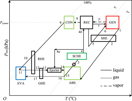
A pressure-temperature-mass fraction (P-T-x) diagram (Figure 4) is drawn to explain the thermodynamic principle of the forced flow diffusion absorption system. The state points correspond to those in Figure 3.
As the same as that in Figure 2, the vertical axis indicates the partial pressure of ammonia in both gas and liquid phases to explain the variation of ammonia pressure in the system. When the system is running, helium only exists in the gas loop thus the processes in CON, REC, GEN, and SHE are the same as those in a traditional single-stage ammonia-water absorption system.
Different from the traditional system, the pressure of ammonia in EVA is not constant due to the equilibrium gas, so does that in ABS. As shown in Figure 4, when the solid line intersects the dotted line in EVA and ABS, the intersection point indicates a vapor-liquid equilibrium state of ammonia including points 11, 15, and 16. For example, due to the sufficient absorption on the surface of the packing, the solution is in phase equilibrium under the ammonia partial pressure at the outlet of ABS (point 15) which is equal to that at point 16. It can be found from Figure 4 that the partial pressure of ammonia at point 17 is the lowest and it rises at the outlet of EVA (11) due to the evaporation of liquid ammonia. In the case of ignoring the heat and mass transfer resistances, the ammonia in EVA is in phase equilibrium at the evaporation temperature, which gradually changes during the diffusion process. The gas with high ammonia content at point 11 is injected into ABS by the ejector, and then it turns into the gas with low ammonia content after ammonia is absorbed in the CON-ABS unit. At the outlet of the CON-ABS unit, the partial pressure of ammonia is coupled to the mass fraction of the solution, so one of the two parameters can be arbitrarily determined at the design stage of the system.
The explanation above provides insight that how the novel system solves the three drawbacks of the traditional system applied on fishing boats. For the first drawback, the approximate single pressure operation of the novel system allows for a simple passive liquid level control without throttling valve regulation; that is, it is not necessary to control the liquid level in GEN to avoid the flooding in the generator, as well as the vapor short circuit between the generator and the absorber, and the vapor short circuit can be easily avoided by liquid seal design. For the second drawback, the approximate single pressure operation allows for the application of a canned solution pump with a low pressure head which is high-efficiency and inherently leak-free, and thus the problem of the solution pump in the traditional system can be solved. For the third drawback, the novel system adopts an integrated cooling strategy; the condenser and the adiabatic absorber are assembled as one unit, and the condensation heat and the absorption heat are removed by a large amount of precooled solution which is sprayed circularly; therefore, the surface area for heat and mass transfer can be ensured even if the system is operated under swaying conditions. Besides, this strategy uses one external seawater cooled heat exchanger rather than two internal seawater cooled heat exchangers (CON and ABS), and thus internal corrosion can be avoided and the reliability of the system is improved.
Modeling
It is necessary to establish the model of the system to investigate its feasibility and features. Whether the system can be operated in the designed way strongly depends on the entrainment performance of the ejector; therefore, the ejector model is carried out separately based on the integrated model of the system.
System Modeling
It should be noticed that the total pressure in the ABS is higher than that in EVA because the pressure difference between ABS and EVA provides the driving force of the gas flow. However, the pressure difference is very small compared with the total pressure in EVA and ABS, and thus the effect of the pressure difference on system performance is very small. Similarly, there is a pressure difference between GEN and EVA, so is there between GEN and ABS. For simplification, the differences are not shown in Figure 4, but the pressure differences are considered in the modeling.
The following assumptions are made to simplify the model.
1) The system operates in a steady state with no heat loss to the environment.
2) The pressure in GEN and REC is uniform, so is that in EVA and the CON-ABS unit. For simplification, the pressure drop in the liquid channel of each heat exchanger is assumed to be 2000 Pa, and that in the gas channel of each heat exchanger is 500 Pa. These values are design-specific and are only used for this case study.
3) The gases in the CON-ABS unit and EVA are only composed of ammonia and helium. The ammonia in the gas at the outlet of EVA is in phase equilibrium.
4) The solution at the outlet of GEN, the liquid ammonia at the outlet of CON, and the ammonia vapor at the outlet of REC are in phase equilibrium. At the outlet of ABS, the solution is in phase equilibrium, corresponding to the partial pressure of ammonia in the gas.
5) The gases in the gas loop are considered to be ideal gases.
6) The rectification efficiency is assumed to be 0.8, and the ammonia mass fraction of the vapor at the outlet of REC is 100%.
7) At the feed stage, the solution is in phase equilibrium with the vapor.
8) The solution before and after the solution pump is assumed as isenthalpic and the efficiency of the solution pump is assumed to be 0.75.
9) The temperature approach is assumed as 5°C for liquid-liquid heat exchange, 10°C for gas-liquid heat exchange, and gas-gas heat exchange.
10) The temperature variation of the solution through SCHE is assumed as 5°C.
The modeling is based on mass, specifies, and energy conservation equations of each component, as shown in Eqs 1–3.
where m, x, h, and Q represent mass flowrate, mass fraction of ammonia, enthalpy, and heat load, and the subscripts i and o represent inlet and outlet, respectively.
The calculation is conducted based on per unit refrigerant mass flowrate (m8 = 1 kg s−1). By assuming the temperatures at the outlets of CON and EVA (T9 and T11), the pressure at the outlet of CON (P9) and the partial pressure of ammonia at the outlet of EVA
The pressures in REC, GEN, EVA, and ABS are calculated by Eqs 6–8.
where
According to assumption (5), the mass fraction of ammonia in the gas at the outlet of EVA is calculated by Eq. 10.
where M is the molecular weight.
As explained in section two that the partial pressure of ammonia changes along the evaporation and absorption processes, there is a mass fraction difference of ammonia in the gas loop,
Similarly, the partial pressure of ammonia in the gas at the gas outlet of ABS
Thus, the gas circulation ratio in the gas loop, defined as the required mass flow rate of the gas entering ABS when per unit mass flow rate of refrigerant is absorbed, is calculated by Eq. 13.
According to assumptions (3) and (4), the gas and liquid temperatures at the outlet of ABS are the same (T15 = T16). The mass fraction of the solution at the outlet of ABS can be calculated by the phase equilibrium equation, as shown in Eq. 14.
where
Based on assumption (4), the solution circulation ratio in the solution loop is calculated by Eq. 15.
where
According to assumptions (6) and (7), the reflux ratio of REC is calculated by Eq. 16.
where
If the feed is saturated or overcooled, the temperature at point seven is assumed as the saturated temperature, while it is the actual temperature if the feed is overheated.
For GEN and REC, the energy conservation equations are shown in Eqs 17–18.
where h and q represent enthalpy and heat load per unit mass flow rate of refrigerant.
For SHE, the energy conservation equation is shown in Eq. 19.
For CON, the energy conservation equation is shown in Eq. 20.
For the ejector and the CON-ABS unit, the energy conservation equation is shown in Eq. 21.
where sr is defined by Eq. 22.
For SCHE, the energy conservation equation is shown in Eq. 23.
For EVA, the energy conservation equation is shown in Eq. 24.
For RHE, the energy conservation equation is shown in Eq. 25.
For GHE, the energy conservation equation is shown in Eq. 26.
Except for the parameters which can be calculated by the equations listed above, the other parameters of each state point can be obtained by phase equilibrium equations and thermodynamic equations of the ammonia-water mixture (Ibrahim and Klein, 1993), as well as that of helium.
For different refrigerant flowrates, the cooling effect and heat input of the system can be calculated by Eqs 27–28, and the COP of the cooling system can be calculated by Eq. 29.
Based on the assumptions and the equations from Eq. 1–29, a routine is programmed to calculate the parameters of each component. When T1, T9, T15, T16, and T11 are assumed according to the operating conditions and the assumptions, the parameters can be calculated in the order of the equations.
Ejector Modeling
The ejector determines whether there is a sufficient gas amount circulated, and its appropriate operation depends on the properly designed geometric parameters under the conditions of the fluids entering and leaving the ejector. A preliminary model is carried out to investigate the feasibility.
The following assumptions are made to simplify the model.
1) There is no external heat exchange.
2) It is assumed that there is no absorption in the ejector due to the fast flow.
3) The involved fluids in the ejector are incompressible.
4) There is no flash evaporation of the motive liquid.
5) The mixing takes place at constant pressure in the mixer.
6) The properties and velocities of the fluids are uniform after the mixer.
7) The effect of gravity is negligible.
8) The energy losses are expressed by the efficiencies of the nozzle, mixer, and diffuser.
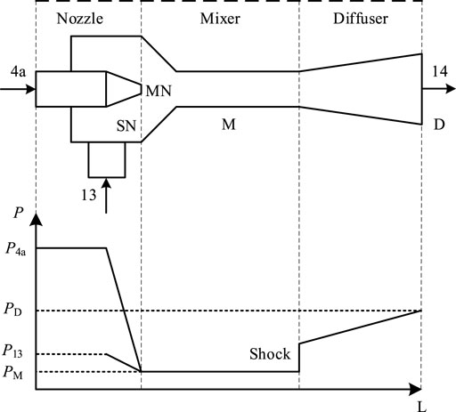
Figure 5 shows the schematic of the ejector and its internal pressure variation.
For the motive nozzle, the energy conservation equation is shown in Eq. 30.
where v, η and ρ represent velocity, efficiency, and density, respectively. The subscripts, MN and M, represent the motive nozzle and the mixer.
For the suction nozzle, the energy conservation equation is shown in Eq. 31.
where The subscript SN represents the suction nozzle and
where R is the gas constant.
For the mixer, the momentum conservation equation is shown in Eq. 33.
For the diffuser, the energy conservation equation is shown in Eq. 34.
where the subscript D represents the diffuser, and the density of the mixture is calculated by Eq. 35 based on assumption (3)
The area of each cross-section is calculated by Eq. 36.
The entrainment ratio is calculated by Eq. 37.
The power consumption of the pump is calculated by Eq. 38.
where
The calculating process is briefly described as follows: first, the initial values of
It should be noted that the energy loss of mixing is minimum when
Results and Discussion
Parameters and Performance Under Given Operating Conditions
A set of operating conditions for freezing is given to carry out the calculation: the mass flow rate of the refrigerant in CON is 0.03°Ckg s−1, and the temperatures at the outlets of GEN, CON, ABS, and EVA are 160, 35, 35°C, and −15°C, respectively. It should be noted that the mass fraction difference of ammonia in the gas loop,
Figure 6 shows the system COP, the gas and solution circulation ratios (fg, fs), and the operating pressure difference of the ejector
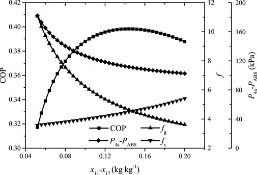
FIGURE 6. The system COP, the gas and solution circulation ratios, and the operating pressure difference of the ejector versus the mass fraction difference of ammonia in the gas loop.
It can be found that the gas circulation ratio decreases rapidly and then flattens out while the solution circulation ratio increases slowly but faster and faster with the increase of
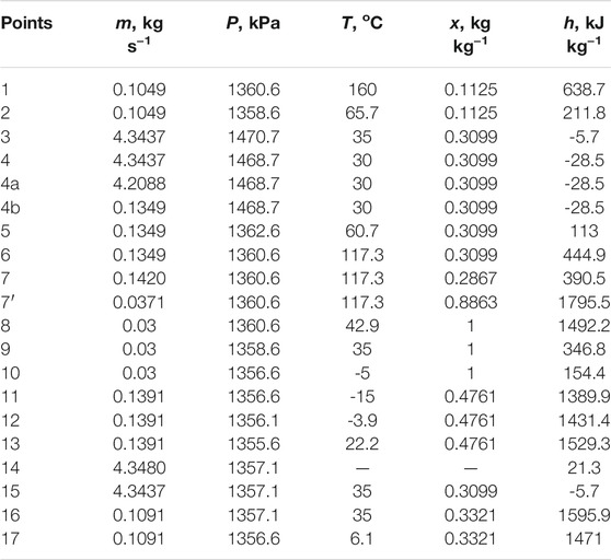
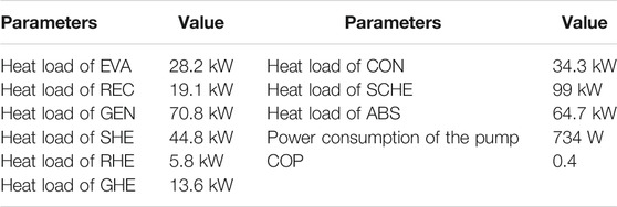
The results indicate that the parameters of each point can be determined. It can be found that the value of
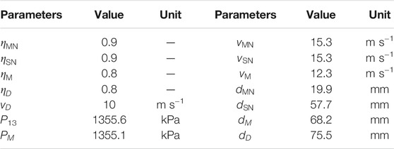
The COP reaches 0.4 and thus the system is proved to be able to work under the given operating conditions. It can be found that the heat loads of RHE and GHE are considerable and affect the cooling effect directly. If the temperature approach of GHE is enlarged, the cooling effect will be reduced. In the extreme, the cooling effect will be reduced to only 8.8 kW and the corresponding COP be just 0.12 if there is no heat recovery by RHE and GHE. The COP of the traditional system is 0.51 under the same operating conditions, and why the COP of the novel system is lower in comparison is explained in The System Performance and Features Under Different Operating Conditions. The parameters of the ejector are shown in Table 3.
Based on the assumptions, the velocities and the diameters of the motive nozzle, suction nozzle, mixer and diffuser can be calculated. It should be noted that the entrainment varies under different operating conditions when the dimension of the ejector is fixed. This may result in an unsatisfactory operation that deviates from the expected performance. Therefore, a motive nozzle with an adjustable diameter design is applicable in practical applications.
The System Performance and Features Under Different Operating Conditions
It is significant to give an insight into the system performance and features under different operating conditions. At the design stage, an optimal COP is expected; therefore, the optimal
Figure 7 shows the variation of the COP, the gas and solution circulation ratios, and the corresponding
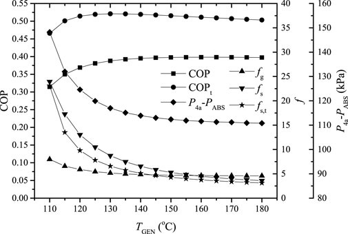
FIGURE 7. The COP, the gas and solution circulation ratios, and the corresponding
As can be seen from Figure 7, the gas and solution circulation ratios decrease rapidly and then tend to become stable with the increase of TGEN; this is caused by the variations of the mass fraction differences of ammonia in the gas and solution loops, which increase rapidly and then become steady. Corresponding to the variation of the gas circulation ratio
In addition, due to the partial pressure variation of ammonia during the absorption and evaporation processes, the partial pressure of ammonia after absorption is lower than that of a traditional single-stage absorption system at the same average evaporation temperature; the mass fraction of the solution after absorption is lower and the solution circulation ratio is increased. Besides, helium is involved in the gas circulation and its temperature variation during the circulation consumes a certain amount of the cooling effect. Because of the two impacts, the COP of the proposed system is lower than that of a traditional single-stage absorption system under the same operating conditions. It should be noted that the average evaporation temperature is taken in the calculation, and the COP of the proposed system is 21–32% lower than that of the traditional single-stage system under the studied operating conditions.
Figure 8 shows the variation of the COP, the gas and solution circulation ratios, and the corresponding
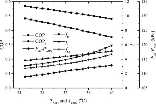
FIGURE 8. The COP, the gas and solution circulation ratios and the corresponding
It can be found that the gas and solution circulation ratios increase as TABS and TCON increase due to the reduction of the mass fraction differences of ammonia in the gas and solution loops. The COP almost linearly decreases with the increase of TABS and TCON, and the proposed system performs worse than the traditional single-stage system, especially at higher TABS and TCON, due to the higher solution circulation ratio and the considerable cooling effect consumption on the pre-cooling of the helium circulated. The value of
Figure 9 shows the variation of the COP, the gas and solution circulation ratios, and the corresponding
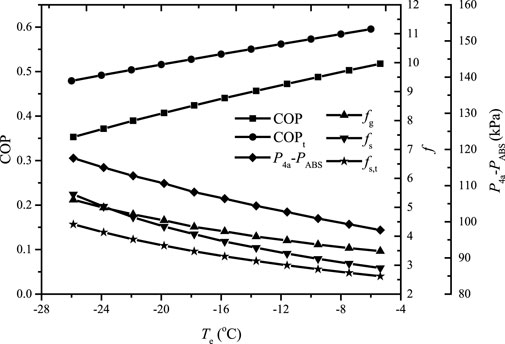
FIGURE 9. The variation of the COP, the gas and solution circulation ratios, and the corresponding
It can be found that the gas and solution circulation ratios decrease smoothly as TEVA increases; therefore, the COP of the proposed system increases almost linearly. The value of
Different pressure drops in the gas channel of each heat exchanger require different pressure heads of the motive solution to ensure the optimal gas circulation ratio. Figure 10 shows
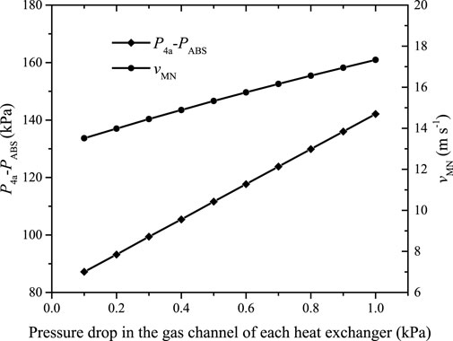
FIGURE 10.
It can be found that
The mass flow rate and the pressure head of the motive fluid are coupled to achieve the entrainment, indicating that the pressure head must necessarily be increased if the mass flow rate of the motive fluid is reduced. Figure 11 shows the variation of the COP, the mass flow rate of the motive solution, and the corresponding
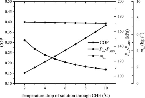
FIGURE 11. The variation of the COP, the mass flow rate of the motive solution, and the corresponding
It can be found the COP decreases slightly with the increase of the temperature drop of the solution through SCHE. Due to the decreased mass flow rate of the motive solution,
The System Control Under Different Exhaust Conditions
Under different exhaust conditions which are caused by the variations in the power output of diesel engines, the system control is much easier compared to a traditional ammonia-water absorption system. There are no throttling valves in the system while the liquid level control is completely passive and the liquid is only stored in the CON-ABS unit. The solution flow is driven by the canned pump, and the gas flow is driven by ejection which is essentially motivated by the canned pump. Therefore, the system works once the canned pump is open, and thus the system control is quite simple. When the exhaust conditions vary, the temperature at the outlet of GEN varies and the performance changes referring to the trend in Figure 7. If a practical system is developed, the ejector is made under design conditions and it is difficult to operate the ejector under the best working conditions for optimal system performance even though the motive nozzle can be adjusted; however, the system COP varies little according to Figure 6. Compared to the COP around 0.5 of the traditional system, the performance of the novel system is indeed lower. However, the COP reduction is the price of being able to apply ammonia-water absorption systems on fishing boats which makes the novel system valuable.
Conclusion
In order to solve the drawbacks relating to reliability, anti-swaying, and anti-corrosion of modularized ammonia-water absorption refrigeration systems with a cooling capacity of 10kW–50kW applied on fishing-boats for frozen preservation, this paper proposes a forced flow diffusion absorption refrigeration system based on evaporative cooling and adiabatic absorption. The uses of throttling valves and the solution pump characterized as high head and low flowrate are eliminated; as a result, the risks of operational failure and leakage can be avoided. The system is composed of four loops; among them, a reliable canned motor pump and an ejector provide the driving forces of the liquid and gas loops. An integral cooling strategy is adopted to remove the condensation and absorption heat in one unit by the precooled recirculated solution, and thus the external heat exchanger cooled by seawater avoids the risk of internal corrosion and leakage. The adiabatic absorption design overcomes the adverse effects of ship swaying because a large amount of spraying solution provides enough area for heat and mass transfer, and simultaneously, provides the motive liquid of the ejector. A thermodynamic model is established, and the analysis results show that the system is valid to be operated under wide operating conditions and the COP reaches 0.4 when the temperatures at the outlets of the generator, evaporator, condenser, and absorber are 160°C, −15°C, 35, and 35°C, respectively. The mass fraction difference of ammonia in the gas loop affects the system performance significantly and there is an optimal value for optimal COP, and thus the optimal gas and solution circulation ratios. The operating pressure difference of the ejector is generally below 170 kPa and such a pressure head is easily achieved by a reliable common canned motor pump. Although the performance of the proposed system is lower than that of a traditional system due to the additional gas loop, it provides a reliable alternative to the current small and medium ammonia-water absorption refrigeration systems.
Data Availability Statement
The original contributions presented in the study are included in the article/supplementary material, further inquiries can be directed to the corresponding author.
Author Contributions
The author confirms being the sole contributor of this work and has approved it for publication.
Funding
This work is supported by National Natural Science Foundation of China under the contract No. 51706133, and Startup Fund for Youngman Research at SJTU is appreciated.
Conflict of Interest
The author declare that the research was conducted in the absence of any commercial or financial relationships that could be construed as a potential conflict of interest.
Publisher’s Note
All claims expressed in this article are solely those of the authors and do not necessarily represent those of their affiliated organizations, or those of the publisher, the editors and the reviewers. Any product that may be evaluated in this article, or claim that may be made by its manufacturer, is not guaranteed or endorsed by the publisher.
References
Aman, J., Henshaw, P., and Ting, D. S.-K. (2018). Performance Characterization of a Bubble Pump for Vapor Absorption Refrigeration Systems. Int. J. Refrig. 85, 58–69. doi:10.1016/j.ijrefrig.2017.09.011
Cerezo, J., Bourouis, M., Vallès, M., Coronas, A., and Best, R. (2009). Experimental Study of an Ammonia–Water Bubble Absorber Using a Plate Heat Exchanger for Absorption Refrigeration Machines. Appl. Therm. Eng. 29 (5-6), 1005–1011. doi:10.1016/j.applthermaleng.2008.05.012
Chandrasekaran, S., Hughes, M., Kini, G., and Garimella, S. (2020). A Microchannel Shell-And-Tube Absorber for Ammonia-Water Absorption. Appl. Therm. Eng. 185, 116321. doi:10.1016/j.applthermaleng.2020.116321
Chen, J., Chang, H., and Chen, S.-R. (2006). Simulation Study of a Hybrid Absorber-Heat Exchanger Using Hollow Fiber Membrane Module for the Ammonia-Water Absorption Cycle. Int. J. Refrig. 29 (6), 1043–1052. doi:10.1016/j.ijrefrig.2006.02.002
Chen, Y., Lin, C., and Tian, Y. (2010). Aqueous Ammonia Solution Cooling Absorption Refrigeration Driven by Sighing Boat Diesel Exhaust Heat. J. Southeast Univ. (English Edition) 26 (2), 333–338.
Chen, X., Du, S., Wang, R. Z., and Lin, P. (2021). Experimental Study of Heat and Mass Transfer for Ammonia-Water Falling Film Absorption on Novel S-Shaped Capillary Tubes Bundle. Int. J. Heat Mass Transfer 164 (4), 120606. doi:10.1016/j.ijheatmasstransfer.2020.120606
Du, S., Wang, R. Z., and Chen, X. (2017). Development and Experimental Study of an Ammonia Water Absorption Refrigeration Prototype Driven by Diesel Engine Exhaust Heat. Energy 130, 420–432. doi:10.1016/j.energy.2017.05.006
Ezgi, C., and Bayrak, S. (2020). Experimental Analysis of a Laboratory-Scale Diesel Engine Exhaust Heat-Driven Absorption Refrigeration System as a Model for Naval Surface Ship Applications. J. Ship Prod. Des. 36 (2), 152–159. doi:10.5957/jspd.2020.36.2.152
Fernández-Seara, J., Vales, A., and Vázquez, M. (1998). Heat Recovery System to Power an Onboard NH3-H2O Absorption Refrigeration Plant in Trawler Chiller Fishing Vessels. Appl. Therm. Eng. 18 (12), 1189–1205. doi:10.1016/S1359-4311(98)00001-5
Garimella, S., Keinath, C. M., Delahanty, J. C., Hoysall, D. C., Staedter, M. A., Goyal, A., et al. (2016). Development and Demonstration of a Compact Ammonia-Water Absorption Heat Pump Prototype with Microscale Features for Space-Conditioning Applications. Appl. Therm. Eng. 102, 557–564. doi:10.1016/j.applthermaleng.2016.03.169
Ibrahim, O. M., and Klein, S. A. (1993). Thermodynamic Properties of Ammonia-Water Mixtures. Ashrae Trans. 99, 1495–1502.
Jakob, U., Eicker, U., Schneider, D., and Teußer, A. (2007). Experimental Investigation of Bubble Pump and System Performance for a Solar Driven 2.5 kW Diffusion Absorption Cooling Machine. Proc. Heat Set 2007, 789–796.
Jiménez-García, J. C., and Rivera, W. (2019). Parametric Analysis on the Experimental Performance of an Ammonia/water Absorption Cooling System Built with Plate Heat Exchangers. Appl. Therm. Eng. 148, 87–95. doi:10.1016/j.applthermaleng.2018.11.040
Lazzarin, R. M., Gasparella, A., and Romagnoni, P. (1996). Experimental Report on the Reliability of Ammonia-Water Absorption Chillers. Int. J. Refrig. 19 (4), 247–256. doi:10.1016/0140-7007(96)00017-5
Liang, X., He, G., Zhou, S., Hao, Z., and Cai, D. (2021). Absorption Characteristics of NH3/NASCN Working Pair in an Adiabatic Absorber with Structured Packing. Appl. Therm. Eng. 185 (1), 116325. doi:10.1016/j.applthermaleng.2020.116325
Oluleye, G., Jiang, N., Smith, R., and Jobson, M. (2017). A Novel Screening Framework for Waste Heat Utilization Technologies. Energy 125, 367–381. doi:10.1016/j.energy.2017.02.119
Ouadha, A., and El-Gotni, Y. (2013). Integration of an Ammonia-Water Absorption Refrigeration System with a Marine Diesel Engine: A Thermodynamic Study. Proced. Comp. Sci. 19, 754–761. doi:10.1016/j.procs.2013.06.099
Palomba, V., Aprile, M., Motta, M., and Vasta, S. (2017). Study of Sorption Systems for Application on Low-Emission Fishing Vessels. Energy 134, 554–565. doi:10.1016/j.energy.2017.06.079
Rodríguez-Muñoz, J. L., and Belman-Flores, J. M. (2014). Review of Diffusion-Absorption Refrigeration Technologies. Renew. Sustain. Energ. Rev. 30, 145–153. doi:10.1016/j.rser.2013.09.019
Salmi, W., Vanttola, J., Elg, M., Kuosa, M., and Lahdelma, R. (2017). Using Waste Heat of Ship as Energy Source for an Absorption Refrigeration System. Appl. Therm. Eng. 115, 501–516. doi:10.1016/j.applthermaleng.2016.12.131
Schmid, F., and Spindler, K. (2016). Experimental Investigation of the Auxiliary Gas Circuit of a Diffusion Absorption Chiller with Natural and Forced Circulation. Int. J. Refrig. 70, 84–92. doi:10.1016/j.ijrefrig.2016.07.012
Schmid, F., Bierling, B., and Spindler, K. (2019). Development of a Solar-Driven Diffusion Absorption Chiller. Solar Energy 177, 483–493. doi:10.1016/j.solener.2018.11.040
Táboas, F., Bourouis, M., and Vallès, M. (2014). Analysis of Ammonia/water and Ammonia/salt Mixture Absorption Cycles for Refrigeration Purposes in Fishing Ships. Appl. Therm. Eng. 66, 603–611. doi:10.1016/j.applthermaleng.2014.02.065
Triché, D., Bonnot, S., Perier-Muzet, M., Boudéhenn, F., Demasles, H., and Caney, N. (2017). Experimental and Numerical Study of a Falling Film Absorber in an Ammonia-Water Absorption Chiller. Int. J. Heat Mass Transfer 111, 374–385. doi:10.1016/j.ijheatmasstransfer.2017.04.008
Ventas, R., Vereda, C., Lecuona, A., Venegas, M., and Rodríguez-Hidalgo, M. D. C. (2012). Effect of the NH3-LiNO3 Concentration and Pressure in a Fog-Jet spray Adiabatic Absorber. Appl. Therm. Eng. 37, 430–437. doi:10.1016/j.applthermaleng.2011.11.067
Wang, H. (2012). A New Style Solar-Driven Diffusion Absorption Refrigerator and its Operating Characteristics. Energ. Proced. 18, 681–692. doi:10.1016/j.egypro.2012.05.083
Yousfi, M. L., Saighi, M., Dalibard, A., Schneider, D., and Eicker, U. (2017). Performance of a 5 kW Hot Water Driven Diffusion Absorption Chiller. Appl. Therm. Eng. 127, 789–799. doi:10.1016/j.applthermaleng.2017.08.035
Yuan, H., Zhang, J., Huang, X., and Mei, N. (2018). Experimental Investigation on Binary Ammonia-Water and Ternary Ammonia-Water-Lithium Bromide Mixture-Based Absorption Refrigeration Systems for Fishing Ships. Energ. Convers. Manag. 166, 13–22. doi:10.1016/j.enconman.2018.04.013
nomenclature
A area, m2
ABS absorber
CON condenser
D diffuser
EVA evaporator
f circulation ratio
GEN generator
GHE gas heat exchanger
h enthalpy, kJ kg−1
m
M molecular weight, kg mol−1
MN motive nozzle
P
Q heat load, kW
q heat load per unit mass flow rate of refrigerant, kW
r reflux ratio
REC rectifier
RHE refrigerant heat exchanger
RTV refrigerant throttling valve
SCHE seawater cooled heat exchanger
SHE solution heat exchanger
SN suction nozzle
STV solution throttling valve
sr ratio of mass flowrate
T temperature, oC
v velocity, m s−1
W power, W
x mass fraction of ammonia, kg kg−1
mass flowrate, kg s−1 Greek letters
ρ density, kg m−3
η efficiency
pressure, kPa Subscripts
g gas
i inlet
o outlet
p pump
s solution
t traditional
w water
Keywords: exhaust waste heat utilization, absorption refrigeration, diffusion, thermal analysis, ammonia-water-helium
Citation: Du S (2021) Thermal Analysis of a Forced Flow Diffusion Absorption Refrigeration System for Fishing-Boat Exhaust Waste Heat Utilization. Front. Energy Res. 9:761135. doi: 10.3389/fenrg.2021.761135
Received: 19 August 2021; Accepted: 01 October 2021;
Published: 21 October 2021.
Edited by:
Thomas Alan Adams, McMaster University, CanadaReviewed by:
Jinchen Tang, Institute of Engineering Thermophysics (CAS), ChinaYanxin Hu, Guangdong University of Technology, China
Copyright © 2021 Du. This is an open-access article distributed under the terms of the Creative Commons Attribution License (CC BY). The use, distribution or reproduction in other forums is permitted, provided the original author(s) and the copyright owner(s) are credited and that the original publication in this journal is cited, in accordance with accepted academic practice. No use, distribution or reproduction is permitted which does not comply with these terms.
*Correspondence: Shuai Du, ZHMwMTA4QHNqdHUuZWR1LmNu
 Shuai Du