- 1School of Environmental and Municipal Engineering, Qingdao University of Technology, Qingdao, China
- 2Shanghai Engineering Research Center of Solid Waste Treatment and Resource Recovery, Shanghai Jiao Tong University, Shanghai, China
- 3School of Metallurgy, Northeastern University, Shenyang, China
Copper slag is a solid pollutant with high recyclability. Reduction and separation are regarded as effective disposal methods. However, during the melting process, the separation and migration behavior of elements in the copper slag is complicated. Thus, the formation of pollutants cannot be controlled merely by optimizing the operation parameters. The elemental distribution and migration behavior are discussed in this work. In reduction experiments, the copper slag smelting liquid was divided into three layers: a reduction slag layer, a reactive boundary layer, and an iron ingot layer. Reduction slag and ingot iron were on the top and bottom of the liquid, respectively. Residual carbon oozed at the interface. C can react with reducible “O” atoms, which exist in 2FeO·SiO2, Fe3O4, and CuO. Meanwhile, CO was generated and overflowed from the liquid layer. After reduction by C or CO, metallic iron and copper were produced and migrated to the iron ingot layer. In the liquid, S gradually diffused into the upper layer. Some of the ZnO and CuS spilled from the liquid into the flume. After reduction, CaO·SiO2 was generated and moved to the upper layer.
1 Introduction
Metallurgical solid waste residue is produced after the extraction of valuable metals. Copper slag is a type of nonferrous metal smelting slag produced in pyrometallurgy. Copper slag is the melt of various oxides and mainly comes from slag-forming components in flux, ore, ash, and reducing agent (fuel) as part of the smelting, converting, and refining three processes in the copper pyrometallurgical procedure (Moskalyk and Alfantazi, 2003).
Depending on the pyrometallurgical process used, copper slag can be divided into smelting slag, blowing slag, refining slag, and dilution slag. The growth rate in recent years would predict that the output of copper slag will exceed 24 million tons by 2020 (Fuentes et al., 2020).
According to the research of typical copper companies in China, the iron and copper grades of copper slag are approximately 40 and 1%, respectively, which are higher than the current grade of iron and copper. Copper slag is a type of secondary resource with a large quantity and high quality. The typical composition of copper slag is Cu 0.42–4.6%; Fe 29–40%; SiO2 30–40%; CaO ≤ 11%; Al2O3 ≤ 10% (Piatak et al., 2015). The copper phase in copper smelting slag is mainly copper sulfide, accounting for more than 60% of the total copper, and followed by copper oxide and copper metal. The iron phase is mainly composed of fayalite and magnetite, the sum of which accounts for more than 80% of the total iron distribution rate, in which the distribution rate of fayalite is 8–65%, and that of magnetite is 33–45%.
The development of new technology, comprehensive utilization of copper slag resources, and extraction of valuable metals, such as iron, and can promote the sustainable development of the metallurgical industry. These technologies are conducive to the rational utilization of secondary resources, which have the dual significance of economic and environmental protection. In the 1970s, China began to study the comprehensive utilization of copper slag, mainly applied to the cement and construction industry, and with various production uses. In the cement industry, it is used as a raw material for cement clinker, cement concrete mixed material, and used as an iron correction agent to produce Portland cement clinker (Shi et al., 2008; Feng et al., 2019; Wang et al., 2020) In the construction industry, it is used in brick making and various cutting blocks and is an alternative to sand for concrete preparation (Kalusuraman et al., 2019; Lan et al., 2020). At home and abroad, research on the recovery of single metal copper from copper slag has been more in-depth and has achieved fruitful results (Zhang et al., 2015; Heo et al., 2016; Liao et al., 2016; Guo et al., 2017; Li et al., 2017). In summary, the current technology mainly includes pyrometallurgy, mineral processing, and the wet method.
The principle of the fire dilution method is that a large amount of Fe3O4 in copper slag leads to an increase in slag viscosity and the loss of copper (Zhang et al., 2005). By reducing the content of magnetic Fe3O4 in slag, the inclusion of copper can be reduced, and the recovery of copper can be achieved (Sun et al., 2020). The common method is to reduce the content of Fe3O4 by adding a reducing agent (carbon powder, broken coal; Eq. 1) and sulfide (FeS, pyrite; Eq. 2).
The technology of reduction modification refers to the technology in which ferroolivine and magnetite in copper slag are reduced to metal iron (MFe) by a reducing agent at a temperature lower than the temperature required to produce liquid iron. With reduction, iron grains continuously precipitate and grow, and the symbiotic relationship with the slag phase changes into a dissemination relationship. Iron is dissociated by grinding and iron is recovered by magnetic separation (Zhang et al., 2015). At present, lignite, coke, hydrogen, and a reducing gas mixture (Zhang et al., 2021) are commonly used as reducing agents. Some scholars have used biomass (Zuo et al., 2016; Zuo et al., 2018), biochar (Zuo et al., 2020a), and plastic coke (Zuo et al., 2021a) as novel cheap reducing agents.
Extraction of a single element from copper slag has been comprehensively studied, but the research focus is limited to a single index of metal recovery. During iron extraction from copper slag, the removal of impurity elements is negligible. Only a few scholars have conducted preliminary research on Fe, Cu, S, As, and P in the process of iron extraction (Cheng et al., 2015; Deegan and Peters, 2017; Meng et al., 2019; Sun et al., 2019; Ming et al., 2020; Zhang et al., 2020).
However, the process of melting separation is commonly used after the reduction of iron and copper. Owing to the lack of understanding of the separation and migration of the main elements in copper slag during melting separation, operation parameters cannot be optimized to control the formation of pollutants to reduce pollution to the environment. The burden of flue gas post-treatment is aggravated after flue gas emission (Bal et al., 2019). For example, people usually use spray washing to remove particulate matter or harmful substances in the flue gas. The design of scrubber structure is closely related to the state of solid particles in flue gas. Understanding the migration of elements is also the basic basis of flue gas treatment (Raj Mohan and Meikap, 2009).
In this study, after the direct reduction reaction of carbon-bearing pellets, chemical composition, XRF, and SEM-EDS analyses were conducted on copper slag, reduction slag, and ingot iron. The migration and transformation behaviors of the elements were studied during the process of melting separation.
2 Experiments and Methods
2.1 Samples
2.1.1 Sample source
The raw materials used in the experiment were copper slag, coal, and limestone. Copper slag was obtained from a flash smelting furnace in Gansu Province, China. The type of coal used in the experiment was lignite and was obtained from a coal mine plant in Liaoning Province. Limestone was ordered online from the Sinopharm Group.
2.1.2 Sample pretreatment
Copper slag and lignite were mechanically crushed into small particles with diameters less than 200 mesh. Limestone was calcined at 1,000°C in a high-temperature vacuum tube furnace for 2 h and then cooled in N2 atmosphere. CaO was obtained by the calcination of limestone. The samples were dried at 105°C for 24 h and then placed in a rapid glass dryer.
2.1.3 Sample components
The chemical component and mineral phase results of copper slag were obtained from our previous work (Zuo et al., 2020b; Zuo et al., 2020a). The chemical components of copper slag are FeO 37.50%; Fe3O4 18.90%; CaO 0.23%; Al2O3 0.98%; MFe 1.24%; SiO2 31.99%; Cu 0.74%; MgO 0.42%; S 0.39%; Zn 2.78%; others 4.87% (Zuo et al., 2020b). The phase of the copper slag is mainly fayalite and magnetite, based on the XRD results. The proximate analysis results of lignite are moisture (3.13%), volatile matter (32.78%), ash (14.3%), and fixed carbon (49.79%) (Zuo et al., 2020a). The purity of CaO was above 99.9%.
2.2 Direct Reduction and Smelting Separation
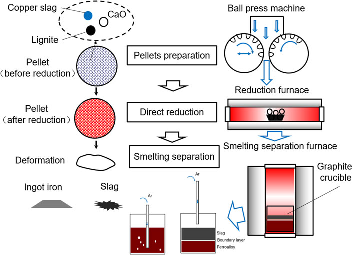
The process of sample treatment, direct reduction, and smelting separation are shown in Figure 1. First, copper slag, lignite, and CaO were thoroughly blended. The mass ratio of copper slag and lignite is based on the molar ratio of “O” and “C”. The mass ratio of the copper slag to CaO is based on the molar ratio of SiO2 and CaO. In this experiment, the molar ratios of C/O and CaO/SiO2, regarded as the optimum reaction conditions, were all 1.0, and based on previous experimental results (Zuo et al., 2017; Zuo et al., 2020b). The masses of lignite and CaO were calculated based on Eqs 7, 8. A carbonaceous pellet with copper slag and CaO was prepared in a spherical shape using a ball-press machine. The maximum diameter of the pellets was 21 mm. The mass of each pellet was approximately 10 g. The pressure setting of the briquetting machine was set to 30 MPa.
where m lignite is the mass of lignite, g; m copper slag is the mass of copper slag, g; m CaO is the mass of CaO, g; Fe3O4% is the mass percentage of Fe3O4 in copper slag, and %; FeO% is the mass percentage of FeO in the copper slag, %.
The pellets were then placed in a corundum crucible in a reduction furnace. The temperature was programmed to heat and kept at 1,150°C for 30 min to achieve the reduction reaction of the copper slag.
Finally, the pellets were placed in a graphite crucible in a smelting-separation furnace with a mass of 460 g. Ar was blown into the melting copper slag using a crucible tube, as shown in Figure 1. Pellets were heated to 1,350°C and held for 15 min. The sample was then cooled in a furnace. The Ar crucible tube was removed from the liquid level and allowed to flow until the temperature of the furnace reached 100°C.
To analyze the feasibility of this technology, economic estimation was calculated based on experimental data and energy consumption of each industrial scale process (Zuo et al., 2021b; Gu, 2021). The calculation results are based on the current price of raw materials and converted into Unites States dollars. For this three steps, the energy consumption is in the form of electricity. In this paper, the energy consumption is transformed into mass of standard coal. By calculation, we can see that this method has great economic benefits. On average, Unites States $ 25.056 can be obtained for each treatment of 100 kg copper slag.
2.3 Analysis Method
Graphite crucible was cut by a chainsaw to obtain slag and ingot iron. The mass of slag, ingot iron, and carburizing powder was then tested. Then, chemical composition, mineral phase, element distribution, and crystal structure of slag, collected dust or iron ingot were analyzed by XRD, and SEM metallurgical microscope.
3 Results and Discussion
3.1 Sample Material Distribution
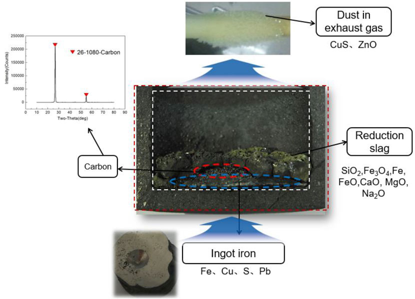
When cooled to room temperature, the copper slag was stratified and solidified. By cutting, the original characteristics of the slag after stratification were retained. A photograph of the copper slag after the layering process is shown in Figure 2. It was eroded to varying degrees inside and outside of the graphite crucible. On the outside of the graphite crucible, oxygen in the air contacted the graphite crucible and carried out oxidation erosion on the outside surface. As shown in Eq. 9, the oxidation erosion of graphite proceeds at the separation temperature. On the inside of the graphite crucible, Ar gas was protected from the surface of the crucible to some extent. However, erosion occurred mainly because of the reaction of metal oxides with graphite on the crucible surface, as shown in Eq. 10. “MeO” represents any metal oxide. The inside erosion phenomenon occurs only when they are in contact with one another.
After reduction and solidification, there was a distinct stratification in the copper slag. The reduction slag is on the top of the solid copper slag, and ingot iron is on the bottom of the solid copper slag. The reduction slag is black brown in color, and tiny pores are present inside the sample. This means that the gas was produced by the reduction reaction, and volatiles were generated.
In addition, on the surface of the reduction slag, there appeared a slightly yellow material. This is due to the release of sulfur from the copper slag, which is removed by the gas. At the bottom, the iron ingot is shaped like a flying saucer. There is an interfacial exudate at the top of the flying saucer, which was analyzed to be residual carbon by XRD, and as shown in Figure 2. The residual carbon oozed at the interface between the iron ingot and the reducing slag. This reveals the direction of material diffusion in the smelting reduction process to some extent.
During the melting separation process, volatile substances are produced as gas dust in the molten pool. These volatiles were deposited on a corundum tube, as shown in Figure 2. Analyzed by XRD, the main components of some dusts are CuS and ZnO. Therefore, it is very important to collect soot volatilized from the copper slag in the molten state to reduce environmental pollution. The mass of the reduction slag, ingot iron, carbon, and volatiles were obtained. The mass percentages of copper slag, lignite, and CaO before reduction were 314.60, 52.61, and 93.92 g, respectively. Mass percentage of reduction slag, ingot iron, carbon, and volatiles (carried dust in gas: CuS, ZnO; gas: CO, CO2) after reduction were 238.5, 222.6, 1.12, and 1.88 g, respectively.
3.2 Reaction Analysis in Copper Slag
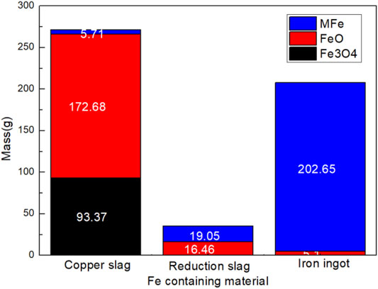
Reactions in the copper slag reduction process were analyzed based on chemical composition tests. Based on the results, we determined the element type and mass content in the sample. The reactions of iron oxide containing a typical reduction reaction are shown in Eq. 10. Mass distribution of Fe, Cu, Zn, S, Pb, as typical elements, and were analyzed as shown in Figures 3, 4. In copper slag, the phases of Fe element are FeO, Fe3O4, and MFe. 86.71% of Fe element moved into iron ingot in the phase of MFe as shown in Figures 3, 4. Some FeO still entered into the reduction slag and ingot respectively. The results confirmed the reduction reaction sequence of iron oxides (Fe3O4-FeO-Fe) to a certain extent.
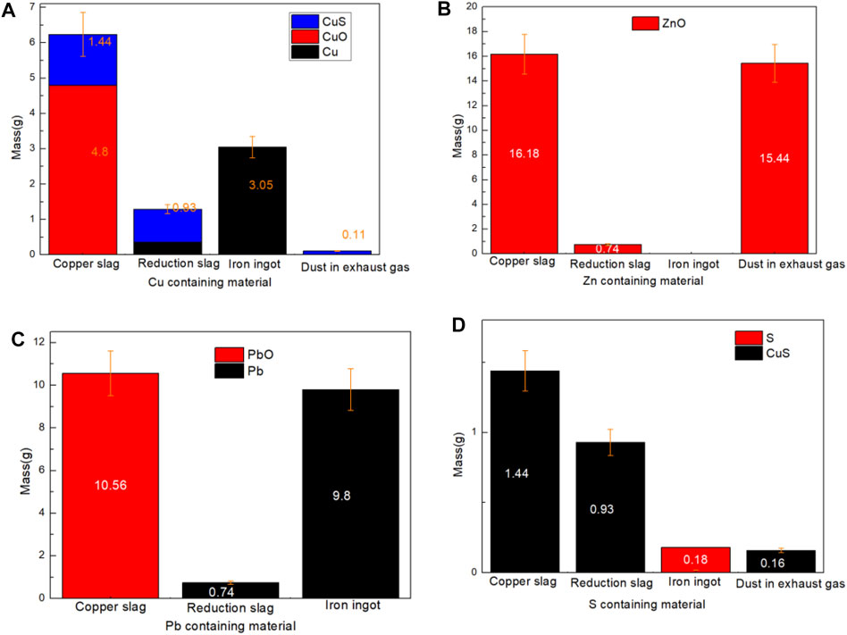
FIGURE 4. Mass distribution of Cu, Zn, Pb, and S containing materials: (A) Cu; (B) Zn; (C) Pb; (D) S.
In copper slag, the phases of Cu element are Cu, CuO, and CuS. 10.17, 86.70, and 3.13% of Cu element moved into reduction slag, iron ingot and somke in the phase of (CuS, Cu), (Cu), and (CuS) respectively, as shown in Figures 4A,D. Although only a small part of CuS enters the flue gas, its polluting characteristics should be paied more attention on recovery study. In the reducing atmosphere, CuO phase has been transformed into Cu phase completely. This is because that, copper is preferentially reduced in the reduction process compared with FeO or Fe3O4.
In copper slag, the phase of Zn element is merely ZnO. As shown in Figures 4B, 5, due to the volatile characteristics of ZnO at high temperature, 94.43% of ZnO entered into the flue gas. Due to the simple element migration, the recovery purity of ZnO powder in flue gas will be relatively high.
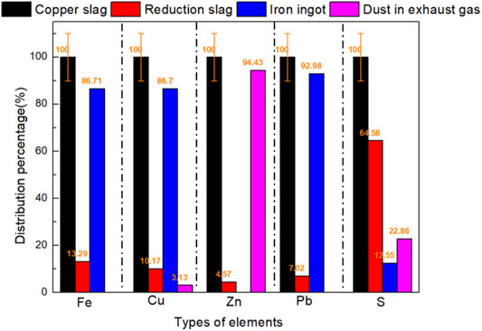
FIGURE 5. Typical elements distribution percentage in copper slag, reduction slag, iron ingot, and dust in exhaust gas.
In copper slag, the phases of S element are S and CuS. As shown in Figures 4D, 5, the distribution of S was obvious. 64.58% of S existed in reduction slag in the phase of CuS and 22.86% of S existed in smoke in the phase of CuS. To capture such volatile solid pollutants, spray soot or spray is usually used to collect such soot, and such as Venturi tube (Bal and Meikap, 2017). However, it should be noted that due to the entry of sulfur-containing substances in copper slag, the corrosion of scrubber needs attention (Sarkar et al., 2007).
In copper slag, the phases of Pb element are Pb and PbO. As shown in Figures 4C, 5, the distribution of Pb was derived by its gravity. 92.98% of Pb element went into iron ingot.
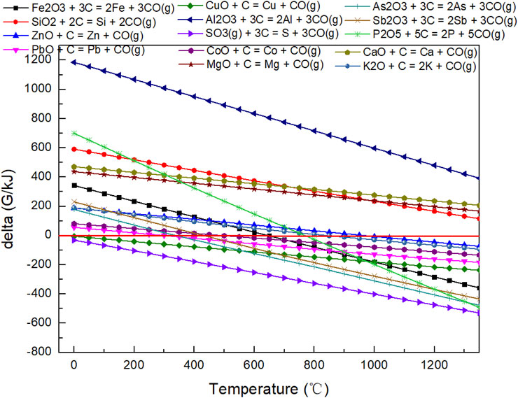
The Gibbs free energy of the reaction of C with oxide materials in copper slag varies with temperature, as shown in Figure 6. We should declare that not all elements in the slag exist in the oxidation state; we only discuss the possible reduction situation as far as possible. As for SiO2, Al2O3, CaO, and MgO, reactions of C with these oxide materials cannot occur when the temperature is higher than 1,150°C. The other reaction of oxide materials with C can take place at this temperature. In other words, during the direct reduction and smelting separation process, Si, Al, Ca, and Mg elements exist in the oxide state, while the other elements cannot stably exist in that state.
3.3 Element Transformation Analysis
Metallographic microscope photos of the copper slag, reduction slag, and ingot are shown in Figure 7. Because of the corrosive effect that occurs during the sample making process, we can find the boundary profile of the metal oxide phase and matrix in the copper slag. At different magnifications, we found that the phases in the copper slag were embedded into the matrix like jelly. After reduction, the metal oxides are stripped from the matrix, and the boundary contour becomes clearer. They are a mixture of iron oxide and slag. As shown in Table 1, in the obtained iron ingot, the black matrix material is mainly fayalite, and which is not fully reacted and is distributed in the iron metal. Some black matrix materials are dots, and some are lines.
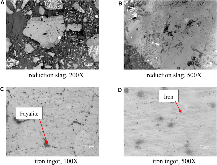
FIGURE 7. Metallographic microscope photos of copper slag and reduction slag: (A) reduction slag, 200X; (B) reduction slag 500X; (C) iron ingot, 100X; (D) iron ingot, 500X.
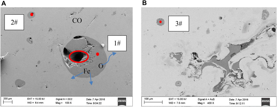
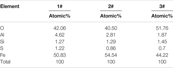
A typical circular area element analysis of the iron ingot is shown in Figure 8A, based on SEM-EDS. In the reduction process, the matrix of fayalite shrinks continuously. As circular areas 1# and 2#, two typical circular fayalite matrices, the radius of the circle is small. The reduction degree of 2# was higher than that of 1#. Chemical analysis of the points was shown in Table 2. The Fe atoms acquired were 54.54 and 50.83% for 2# and 1#, respectively. Through the element distribution and the changes in the size of the circles in these two areas, we can determine the migration rule of elements (O, Al, Si, Fe, and S) inside the circle. Fe and O are mainly present in the matrix of the black circle in the form of FeO. The small holes in the circle matrix are caused by the release of O atoms and migrate to the produced gas. The Fe atom migrates from the inside to the outside of the circle matrix continuously. Al and Si are all present in the slag phase. The S element exists in the circle matrix at the initial stage of reduction, and the concentration of S decreases at the later reduction stage. Another typical circle matrix region, such as 3#, is shown in Figure 8B. Atom percentages of Fe is 44.22%. The results further confirmed the migration order of Fe and O and confirmed the regional variation relationship of the matrix. It should be noted that the proportions of Cu and S atoms were significantly higher than elsewhere in 1#, 2#, and 3#. This indicates that during the reduction process, Cu and S are in the CuS phase, and part of the CuS will migrate to the produced gas.
3.4 Element Migration Mechanism of Smelting Copper Slag
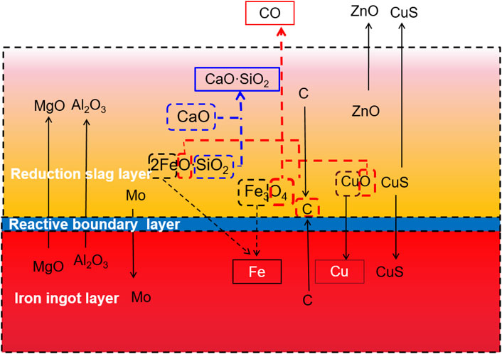
The element migration behavior during the separation process is accompanied by a partial reduction reaction. During melting separation, the liquid is divided into three layers: a reduction slag layer, a reactive boundary layer, and an iron ingot layer. The element migration process and mechanism follow the rules described below. A diagram of the element migration mechanism of smelting copper slag in a reducing atmosphere is shown in Figure 9.
Because melting separation is carried out in a graphite crucible, C powder participates in a secondary reduction reaction during the separation process. C reacts with reducible “O” atoms, which exist in 2FeO·SiO2, Fe3O4, CuO forms, and CO is generated and overflows the liquid layer.
According to the analysis of the chemical composition and phase in the slag, it can be found that the Fe atom in the copper slag mainly exists in the 2FeO·SiO2 and Fe3O4 phases. After reduction by C or CO, metallic iron is produced and migrates downward to the iron ingot layer because of its higher density. The Cu in the melting liquid is in the form of CuO and CuS. Like Fe, CuO is reduced by C, and metallic copper is produced and migrates downward to the iron ingot layer because of its higher density. The reduction reaction is more likely to occur than the iron oxide reduction reaction.
S exists mainly in the form of CuS. Based on the chemical composition analysis, the weight percentages of S in the copper slag, reduction slag, and iron ingot were 0.84, 1.20, and 0.051%, respectively. This indicates that the migration of S in the liquid gradually moves from diffusion to the upper reduction slag layer. Through the chemical composition analysis of the upper layer reduction slag and the phase analysis of the products in the flue gas, it was found that there was a large amount of ZnO and CuS dust in the smoke. Thus, much of the ZnO and CuS spilled from the liquid into the smoke.
As for Si, it exists mainly in the form of 2FeO·SiO2. When CaO is in contact with 2FeO·SiO2, desilication and slagging reactions occurred, as shown in Eq. 11. After the reaction, CaO·SiO2 is generated and ascends to the upper reduction slag layer because of its lower density.
4 Conclusion
Pellet direct reduction and metal separation is regard as an efficient way to dispose copper slag. The element distribution and migration step during the copper slag reduction and smelting separation processes are obtained in this paper.
1) During melting separation, the copper slag liquid is divided into three layers. The residual carbon oozed at the interface between the iron ingot later and the reducing slag layer.
2) Based on the SEM-EDS analysis, Fe and O mainly existed in the matrix and in the form of FeO. The small holes in the matrix were caused by the release of O atoms. The Fe atoms migrated continuously from the inside to the outside of the circle matrix. Cu and S were present in the CuS phase.
3) As typical elements, Fe, Cu, Zn, S, and Pb’s distribution were analyzed based on element chemical analysis in three layers. As the main migration route, 86.71% of Fe element moved into iron ingot in the phase of MFe; 86.70% of Cu element moved into iron ingot; 94.43% of ZnO entered into the flue gas; 64.58% of S existed in reduction slag in the phase of CuS; 92.98% of Pb element went into iron ingot.
4) C reacted with reducible “O” atoms, which exist in 2FeO·SiO2, Fe3O4, and CuO. CO is generated and overflowed from the liquid layer. Metallic iron and copper were produced and migrated to the iron ingot layer. S migrates in the liquid gradually to the upper reduction slag layer. CaO·SiO2 was generated, which went up to the upper layer.
Data Availability Statement
The original contributions presented in the study are included in the article/Supplementary Material, further inquiries can be directed to the corresponding author.
Author Contributions
ZZ wrote the article and organized the experiments. SL and QY provided the experiment equipment. The other authors analyzed the datas.
Funding
This research has been supported by the Natural Science Foundation of Shandong Province (ZR2020QE150 and ZR2019MEE015), the key research and development plan of Shandong Province (2018GSF117042).
Conflict of Interest
The authors declare that the research was conducted in the absence of any commercial or financial relationships that could be construed as a potential conflict of interest.
Publisher’s Note
All claims expressed in this article are solely those of the authors and do not necessarily represent those of their affiliated organizations, or those of the publisher, the editors and the reviewers. Any product that may be evaluated in this article, or claim that may be made by its manufacturer, is not guaranteed or endorsed by the publisher.
References
Bal, M., and Meikap, B. C. (2017). Prediction of Hydrodynamic Characteristics of a Venturi Scrubber by Using CFD Simulation. South Afr. J. Chem. Eng. 24, 222–231. doi:10.1016/j.sajce.2017.10.006
Bal, M., Siddiqi, H., Mukherjee, S., and Meikap, B. C. (2019). Design of Self Priming Venturi Scrubber for the Simultaneous Abatement of HCl Gas and Particulate Matter from the Flue Gas. Chem. Eng. Res. Des. 150, 311–319. doi:10.1016/j.cherd.2019.08.005
Cheng, C., Xue, Q., Wang, G., Zhang, Y., and Wang, J. (2015). Phosphorus Migration during Direct Reduction of Coal Composite High-Phosphorus Iron Ore Pellets. Metall. Materi Trans. B 47 (1), 154–163. doi:10.1007/s11663-015-0479-7
Deegan, M. M., and Peters, J. C. (2017). CO Reduction to CH3OSiMe3: Electrophile-Promoted Hydride Migration at a Single Fe Site. J. Am. Chem. Soc. 139 (7), 2561–2564. doi:10.1021/jacs.6b12444
Feng, Y., Yang, Q., Chen, Q., Kero, J., Andersson, A., Ahmed, H., et al. (2019). Characterization and Evaluation of the Pozzolanic Activity of Granulated Copper Slag Modified with CaO. J. Clean. Prod. 232, 1112–1120. doi:10.1016/j.jclepro.2019.06.062
Fuentes, I., Ulloa, C., Jimenez, R., and Garcia, X. (2020). The Reduction of Fe-Bearing Copper Slag for its Use as a Catalyst in Carbon Oxide Hydrogenation to Methane. A Contribution to Sustainable Catalysis. J. Hazard. Mater. 387, 121693. doi:10.1016/j.jhazmat.2019.121693
Gu, J. (2021). Experiment and Energy Consumption Analysis of Direct Reduction & Melting Separation Process for Low-Grade Composite Iron Ore. Beijing: Beijing University of Technology.
Guo, Z., Zhu, D., Pan, J., Zhang, F., and Yang, C. (2017). Industrial Tests to Modify Molten Copper Slag for Improvement of Copper Recovery. JOM 70 (4), 533–538. doi:10.1007/s11837-017-2671-5
Heo, J. H., Chung, Y., and Park, J. H. (2016). Recovery of Iron and Removal of Hazardous Elements from Waste Copper Slag via a Novel Aluminothermic Smelting Reduction (ASR) Process. J. Clean. Prod. 137, 777–787. doi:10.1016/j.jclepro.2016.07.154
Kalusuraman, G., Thirumalai Kumaran, S., Aslan, M., Küçükömeroğluc, T., and Siva, I. (2019). Use of Waste Copper Slag Filled Jute Fiber Reinforced Composites for Effective Erosion Prevention. Measurement 148, 106950. doi:10.1016/j.measurement.2019.106950
Lan, W., Wu, A., and Yu, P. (2020). Development of a New Controlled Low Strength Filling Material from the Activation of Copper Slag: Influencing Factors and Mechanism Analysis. J. Clean. Prod. 246, 119060. doi:10.1016/j.jclepro.2019.119060
Li, B., Wang, X., Wang, H., Wei, Y., and Hu, J. (2017). Smelting Reduction and Kinetics Analysis of Magnetic Iron in Copper Slag Using Waste Cooking Oil. Sci. Rep. 7 (1), 2406. doi:10.1038/s41598-017-02696-y
Liao, Y., Zhou, J., and Huang, F. (2016). Separating and Recycling of Fe, Cu, Zn from Dumped Copper Slag by Microwave Irradiation Assisted Carbothermic Method. J. Residuals Sci. Technol. 13 (S1), S155–S160. doi:10.12783/issn.1544-8053/13/S1/22
Meng, D.-L., Chen, C.-H., Yi, J.-D., Wu, Q., Liang, J., Huang, Y.-B., et al. (2019). Migration-Prevention Strategy to Fabricate Single-Atom Fe Implanted N-Doped Porous Carbons for Efficient Oxygen Reduction. Research 2019, 1768595. doi:10.34133/2019/1768595
Ming, J., Xin, S., Yongmei, H., Bo, L., Fangdong, Z., Tianguo, L., et al. (2020). Migration and Transformation Behavior of Heavy Metal Elements during the Calcination Process of Copper Slag. Appl. Chem. Industry 49 (7), 1703–1705. doi:10.16581/j.cnki.issn1671-3206.20200416.007
Moskalyk, R. R., and Alfantazi, A. M. (2003). Review of Copper Pyrometallurgical Practice: Today and Tomorrow. Minerals Eng. 16 (10), 893–919. doi:10.1016/j.mineng.2003.08.002
Piatak, N. M., Parsons, M. B., and Seal, R. R. (2015). Characteristics and Environmental Aspects of Slag: A Review. Appl. Geochem. 57, 236–266. doi:10.1016/j.apgeochem.2014.04.009
Raj Mohan, B., and Meikap, B. C. (2009). Performance Characteristics of the Particulate Removal in a Novel Spray-Cum-Bubble Column Scrubber. Chem. Eng. Res. Des. 87, 109–118. doi:10.1016/j.cherd.2008.05.011
Sarkar, S., Meikap, B. C., and Chatterjee, S. G. (2007). Modeling of Removal of Sulfur Dioxide from Flue Gases in a Horizontal Cocurrent Gas-Liquid Scrubber. Chem. Eng. J. 131, 263–271. doi:10.1016/j.cej.2006.12.013
Shi, C., Meyer, C., and Behnood, A. (2008). Utilization of Copper Slag in Cement and concrete. Resour. Conservation Recycling 52 (10), 1115–1120. doi:10.1016/j.resconrec.2008.06.008
Sun, Y.-S., Li, Y.-F., Han, Y.-X., and Li, Y.-J. (2019). Migration Behaviors and Kinetics of Phosphorus during Coal-Based Reduction of High-Phosphorus Oolitic Iron Ore. Int. J. Miner Metall. Mater. 26 (8), 938–945. doi:10.1007/s12613-019-1810-0
Sun, Y., Chen, M., Cui, Z., Contreras, L., and Zhao, B. (2020). Equilibria of Iron Silicate Slags for Continuous Converting Copper-Making Process Based on Phase Transformations. Metall. Mater. Trans. B 51 (5), 2039–2045. doi:10.1007/s11663-020-01901-0
Wang, Q., Li, Z., Li, D., Tian, Q., Guo, X., Yuan, Z., et al. (2020). A Method of High-Quality Silica Preparation from Copper Smelting Slag. JOM 72 (7), 2676–2685. doi:10.1007/s11837-020-04196-3
Zhang, L., Zhang, L., and Mingyu, W. (2005). Oxidization Mechanism in CaO-FeOx-SiO2 Slag with High Iron Content. Trans. Nonferrous Met. Soc. China 15 (4), 938–943.
Zhang, J., Qi, Y.-h., Yan, D.-l., and Xu, H.-c. (2015). A New Technology for Copper Slag Reduction to Get Molten Iron and Copper Matte. J. Iron Steel Res. Int. 22 (5), 396–401. doi:10.1016/s1006-706x(15)30018-2
Zhang, J., Luo, G., Chen, Y., Xin, W., and Zhu, J. (2020). Phosphorus Migration Behavior of Medium-Phosphorus Magnetite Ore during Carbothermic Reduction. ISIJ Int. 60 (3), 442–450. doi:10.2355/isijinternational.ISIJINT-2019-214
Zhang, H., Bao, L., Chen, Y., Xuan, W., and Yuan, Y. (2021). Efficiency Improvements of the CO-H2 Mixed Gas Utilization Related to the Molten Copper Slag Reducing Modification. Process Saf. Environ. Prot. 146, 292–299. doi:10.1016/j.psep.2020.09.011
Zuo, Z., Yu, Q., Wei, M., Xie, H., Duan, W., Wang, K., et al. (2016). Thermogravimetric Study of the Reduction of Copper Slag by Biomass. J. Therm. Anal. Calorim. 126 (2), 481–491. doi:10.1007/s10973-016-5570-z
Zuo, Z., Yu, Q., Liu, J., Qin, Q., Xie, H., Yang, F., et al. (2017). Effects of CaO on Reduction of Copper Slag by Biomass Based on Ion and Molecule Coexistence Theory and Thermogravimetric Experiments. ISIJ Int. 57 (2), 220–227. doi:10.2355/isijinternational.ISIJINT-2016-402
Zuo, Z., Yu, Q., Xie, H., Wang, K., Liu, S., Yang, F., et al. (2018). Mechanical and Reduction Characteristics of Cold-Pressed Copper Slag Pellets Composited within Biomass and lignite. Renew. Energ. 125, 206–224. doi:10.1016/j.renene.2018.02.057
Zuo, Z., Yu, Q., Xie, H., Yang, F., Han, Z., and Qin, Q. (2020a). Direct Reduction of Copper Slag-Carbon Composite Pellets by Coal and Biochar. Environ. Technol. 41 (17), 2240–2252. doi:10.1080/09593330.2018.1561757
Zuo, Z., Yu, Q., Luo, S., Zhang, J., and Zhou, E. (2020b). Effects of CaO on Two-step Reduction Characteristics of Copper Slag Using Biochar as Reducer: Thermodynamic and Kinetics. Energy Fuels 34 (1), 491–500. doi:10.1021/acs.energyfuels.9b03274
Zuo, Z., Feng, Y., Li, X., Luo, S., Ma, J., Sun, H., et al. (2021a). Thermal-Chemical Conversion of Sewage Sludge Based on Waste Heat cascade Recovery of Copper Slag: Mass and Energy Analysis. Energy 235 (15), 121327. doi:10.1016/j.energy.2021.121327
Keywords: copper slag, element migration, reduction, pollutants, element separation
Citation: Zuo Z, Feng Y, Luo S, Dong X, Li X, Ren D, Yu Q and Guo J (2021) Element Distribution and Migration Behavior in the Copper Slag Reduction and Separation Process. Front. Energy Res. 9:760312. doi: 10.3389/fenrg.2021.760312
Received: 18 August 2021; Accepted: 23 November 2021;
Published: 09 December 2021.
Edited by:
Kaiqiang Zhang, Imperial College London, United KingdomReviewed by:
Sang-Sup Lee, Chungbuk National University, South KoreaB. C. Meikap, Indian Institute of Technology Kharagpur, India
Copyright © 2021 Zuo, Feng, Luo, Dong, Li, Ren, Yu and Guo. This is an open-access article distributed under the terms of the Creative Commons Attribution License (CC BY). The use, distribution or reproduction in other forums is permitted, provided the original author(s) and the copyright owner(s) are credited and that the original publication in this journal is cited, in accordance with accepted academic practice. No use, distribution or reproduction is permitted which does not comply with these terms.
*Correspondence: Siyi Luo, bHVvc2l5aTY2NkAxMjYuY29t
 Zongliang Zuo
 Yan Feng
 Siyi Luo
 Xinjiang Dong
 Xiaoteng Li
 Dongdong Ren
 Qingbo Yu3