- 1School of Aeronautics and Astronautics, Central South University, Changsha, China
- 2College of Astronautics, Nanjing University of Aeronautics and Astronautics, Nanjing, China
The challenge of the powder-fuel ramjet is to improve the mixing effect of powder-fuel with oxidizing agents and combustion efficiency. To improve the mixing and combustion efficiency of the powder-fuel ramjet engine, three configurations in head shapes and three exhaust gas inlet patterns of the engine are designed based on a typical powder-fuel ramjet engine combustion chamber. The effect of the head shapes and exhaust gas inlet patterns is analyzed and compared by the three-dimensional numerical simulation method. A comprehensive model validation is built, and the calculation results of the k-ε standard model are compared with the experimental data. The results show that the cylindrical head forms a recirculation zone at the head of the combustion chamber, which leads to powder deposition in the head region of the chamber. The design with the round head and the coned head reduces the recirculation inside the head region, and the exhaust gas from the fuel gas generator has benefits in powder injection and mixing inside the combustion chamber. The exhaust gas inlet of the inclined six hole type has benefits in the mixing of powder and high temperature exhaust gas because it generates strong flow impingement in the core part of the chamber.
Introduction
The powder-fuel ramjet engine combines the advantage of the solid ramjet and the liquid ramjet engine and has drawn a lot of attention in recent years. It uses high-energy metal/non-metal powder as fuel for combustion (Woosuk et al., 2018). It obtains high combustion efficiency and an adjustable fuel supplying rate like a liquid ramjet engine. In addition, it has simple structures, high reliability and easy maintenance like a solid ramjet engine. More and more researchers try to use new fuels in ramjets (Singh and Walker, 2015). Metal fuels can achieve large heat release and high specific impulse in the combustion process compared with traditional hydrocarbon fuels (Goroshin et al., 2001).
Compared with a solid ramjet engine, the flow rate of the powder fuel is easier to be adjusted like one kind of fluid fuel (Gong et al., 2017). In addition, due to the high energy density in the metal powder, the engine can obtain high specific impulse. However, it is difficult to achieve a self-sustaining burn depending on metal powder because a combustion environment of high temperature is required for metal powder. Xu et al. (Xu et al., 2019) designed a hybrid powder–solid fuel ramjet (HPSR). Although the problem of the high-temperature combustion environment has been improved in an HPSR, some new problems about combustion efficiency and flame stabilization have to be solved. For Mach numbers in excess of those for which turbojet concepts can be used, subsonic burning ramjet concepts are used until their Mach number limit is reached (Bertin and Cummings, 2003). Flow structures in a powder-fuel ramjet have changed a lot compared with the traditional scramjet combustor, and the traditional strategy of flame stability needs some modifications (Liu et al., 2020a). Owing to the high combustion requirements of metal particles, some strategies are needed to sustain the combustion, which also brings about other problems such as deposits of combustion products, excessive pressure loss, and low mixing efficiency (Li et al., 2019). These problems can be solved by using a flame stabilizer designed by Hsu et al. (Hsu et al., 1995). However, the design of the flame stabilizer increases the complexity of the structure and reduces reliability.
Many research studies about powder combustion in a powder-fuel ramjet have been performed, including the research centers of NASA and ONERA. Linnell and Miller (2002) analyzed the ramjet with a combustion chamber at a pressure around 250 kPa, and a thrust of 2900 N and specific impulse of 400 s were achieved. Goroshin et al. (1999) found that the combustor operating at fuel-rich conditions has benefits for the combustion stability. An experimental prototype of a powder-fuel ramjet was built and tested in ONERA (A (2002). Ramjet scra, 2002), which laid the foundation for experimental measurements. Miller and Herr (2004) measured effectiveness of these powder-fuel systems, and the related thrust and specific impulse at conditions were obtained. Abbud-Madrid et al. (2001) also tried to use metal and high-energy non-metal powder as engine fuels. It is found that the residual time and powder size can affect the flame shape and the burning rate. Shafirovich et al. (1993)and Shafirovich and Varma (2008) tested the burning of magnesium powder particles with carbon dioxide. It is concluded that magnesium is the most promising fuel with the relatively high-specific impulse and easy inflammability in CO2. The results also show that the reaction of aluminum and carbon dioxide in the ramjet and turbojet engines is feasible. Recently, boron powder has drawn some attention as the fuel for powder ramjet engines (Abdalla et al., 2020). Gany (2015) has studied the boron powder combustion applied in the ramjet combustors. Regarding the blocking phenomenon caused by the thermodynamic reaction at high temperature and pressure, the blocking phenomenon becomes worse at a high ratio of boron/air. Rashkovskiy (2019) developed the model of the residue formation in the combustion chamber with boron powder propellants. Li et al. (2016) investigated an aluminum powder-fuel ramjet, and they found that the increased mass rate of the fluidization gas improved the mixing efficiency.
Mixed compression inlets and isolators exhibit a series of such interactions at different Mach numbers and boundary layer thicknesses (Gaitonde, 2015). The geometric shape of the combustion chamber has a great influence on the blending efficiency (Chelaru and Mingireanu, 2011). Different powder injection arrangements and air inlet patterns were studied by Stowe et al. (2004), such as the angle between the powder injection and the air inlets, the axial distance from the burner head to the air inlets, and the angle between the two air inlets. The main problem that exists in the powder-fuel ramjet is to enhance the mixing effect of the air and the powder fuel (Huang et al., 2020). It is necessary to search for an optimized shape of the combustion chamber and an improved exhaust injection pattern for a powder-fuel ramjet (Li et al., 2021). Because the research work on powder injection and combustion chamber design is in a preliminary stage, some experience and related parameters of solid fuel injection of a solid rocket ramjet are referred.
From the above, there are limited research studies about the design of the combustion chamber in a powder-fuel ramjet to improve the mixing. In the present work, effects of different designs on the head shapes and inlet patterns are considered. Based on a certain typical powder-fuel ramjet, three configurations in head and three exhaust inlet patterns of the engine are designed. The influence of the structural design is analyzed and compared by the three-dimensional numerical simulation method. The mixing efficiency, pressure loss, and relative density distributions are analyzed to provide some references for the design the combustion chamber. Because of the poor deposition and mixing effect in the head region of a powder fuel ramjet, a parametric study of head shapes and gas inlet patterns is performed to improve the mixing efficiency and avoid deposition. The optimal structure of the combustion chamber is proposed for initial design of a powder-fuel ramjet.
Geometric Model
Combustion Chamber of a Typical Powder-Fuel Ramjet
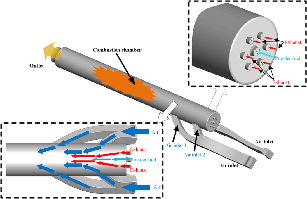
Based on the aforementioned research works, a typical combustion chamber model of the powder-fuel ramjet is created (Figure 1). The oxidizer, air, enters the combustion chamber through two separated air inlets mounted on the combustion chamber along the streamwise direction, shown as air inlet 1 and air inlet 2 in the figure. The air supplied from air inlet 1 makes the air-to-powder ratio close to the equivalent ratio and then meets the requirements of engine startup and ignition (Auerswald et al., 2020). Air from air inlet 2 increases the air-to-powder ratio to improve the specific impulse of the engine and combustion efficiency. There are some exhaust inlets arranged on the head of the combustion chamber. The high-temperature and high-speed exhaust is injected into the combustion through these exhaust inlets. The powder fuel is injected from the central inlet on the head of the chamber by the fluidization gas. The working medium of the fluidization process is air. The fluidizing powder mixes with the exhaust from the exhaust inlet, air from air inlet 1 and air inlet 2 in the combustion chamber.
Computational Domain
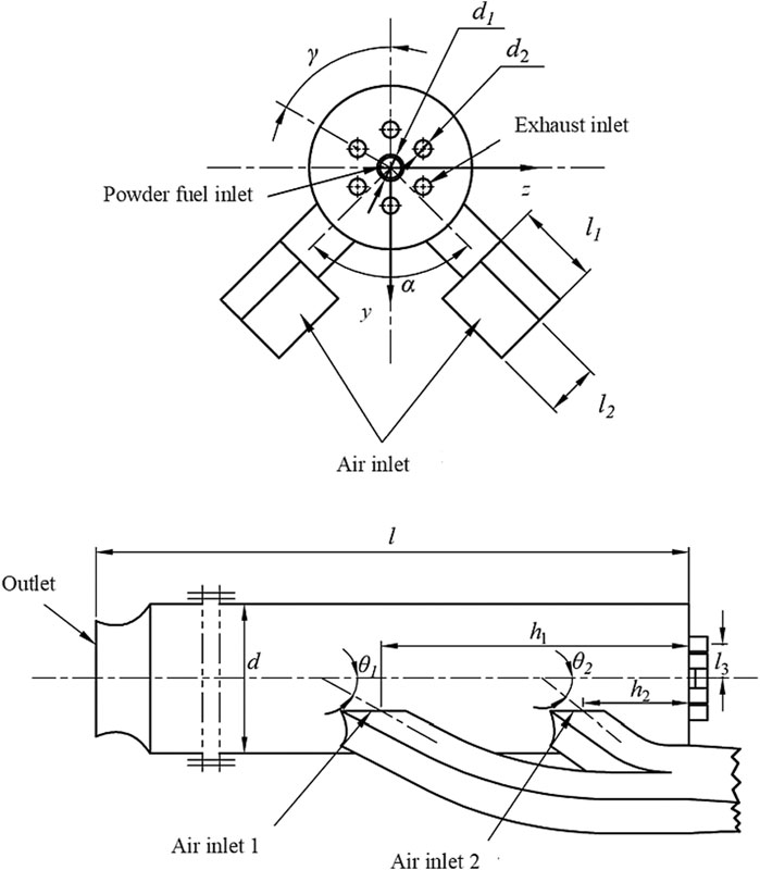
From the published articles, some parameters of a solid rocket ramjet are given in Table 1. In the table, the geometric configuration of the experimental combustor and test conditions are available. Figure 2 shows the related geometric parameters of the combustion chamber. The diameter of the combustion chamber is 160 mm (d) with a length of 1,560 mm (l). The simplified engine has six main exhaust nozzles, with a diameter of 16 mm (d2). They are distributed circumferentially at an angle of 60 degrees. The diameter of the powder inlet is 21 mm (d1). The lengths of the two rectangular air inlets on the side wall are 82 mm (l1) and 52 mm (l2), respectively. From the top view, the angle between the two air inlets is 90 degrees. To study the influence of the structural shape in the head and exhaust inlet of the combustion chamber on the mixing and engine performance, dome height 1, dome height 2, and the distance between the high-temperature exhaust inlet center and the fuel inlet center are fixed at 110 mm (h1), 330 mm (h2), and 37 mm (l3), respectively.
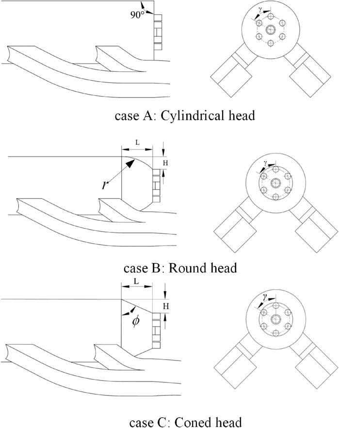
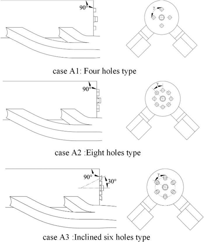
Based on the traditional design with a cylindrical head and six exhaust inlets type (case A) Chuang et al. (1989), two modified designs varied in head shapes and three exhaust inlet patterns were built aiming at improving the mixing efficiency. The head shapes of case B and case C are designed as a round head type and a coned head type, respectively, as shown in Figure 3 (case B) and (case C). In Figure 4, the high-temperature exhaust inlet is designed as four-hole type in case A1 and eight-hole type in case A2. Case A3 is designed as six inclined holes, with an inclination angle of 30 degrees. The details of the six configurations are described as follows:
Case A: basic model, cylindrical head, six exhaust inlets. Case B: round head with spherical diameter of 243 mm, six exhaust inlets. Case C: coned head with the inclined contracted angle of 22 degrees, six exhaust inlets
Case A1: cylindrical head, four exhaust inlets
Case A2: cylindrical head, eight exhaust inlets
Case A3: cylindrical head, six inclined exhaust inlets with an inclination angle of 30 degrees
Computational Methodology
Governing Equations and Model Validation
In the calculations, three turbulence models are tested and compared. Commercial CFD software ANSYS Fluent 19.0 Liu et al. (2020b) is used for simulation. It uses parallel algorithm to solve the three-dimensional Navier–Stokes equation in a structured multi-block grid system. In order to simulate the compressible flow regime, a density-based solver scheme Roe (2003) is applied.
Murty and Chakraborty (2012) used the k-ε standard model in the study of mixing effects and obtained pretty accurate results. The transport equations of k and ε are shown as following two equations:
and
In the two equations, μt is written as follows:
The species transport equation is also used in this article, and this conservation equation takes the following general form:
where Ri is the net rate of production of species i by chemical reaction and Si is the rate of creation by addition from the dispersed phase plus any user-defined sources.
The k-ε standard turbulence model has been used in this work. The pressure values predicated by the turbulence model and the pressure measured by the experiments in the combustion chamber of the ramjet are compared in Figure 5. Obviously, the predicted results by the k-ε standard model have good agreement with the trend with the tested result and the ratio of pressure to total pressure at each pressure measurement locations along the axis in different operation conditions is nearly overlapped. Since the three cross-sectional areas show a trend of increasing and then decreasing, the pressure ratio shows a trend of decrease and then increase. In addition, the results show that the model has good stability and the obtained value has acceptable deviations in a certain range of fluctuations. It should be pointed out that there are some inevitable differences between simulation results and experimental results. For example, the pressure test region has relatively large disturbance by the instruments. However, the fluctuation can be ignored in the simulation process, and the pressure change is not obvious. Therefore, the k-ε standard model has shown enough validations for later calculations.
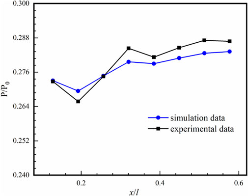
FIGURE 5. Turbulence model validation: the value of P/P0 on y-z sections along the streamwise direction at different locations between simulation and experimentation.
Boundary Conditions
In the present work, the mixing effect of high-temperature exhaust and the powder is replaced by the mixing of high-temperature exhaust (H2O and CO2) with air ejecting from the central inlet. Table 2 gives the related parameters of air and high-temperature exhaust and the boundary conditions of the work. The assumptions in the calculations are listed as follows.
1 The fluidized gas of powder is assumed as air.
2 The exhaust is assumed as H2O and CO2. There are many substances in the high-temperature exhaust, but only the CO2 and H2O vapors are considered.
3 The gas in the combustion chamber is adiabatic without heat exchange with the surrounding environment.
4 Gaseous radiation and body force are ignored.
5 High-temperature exhaust is regarded as an ideal gas.
Mesh Generation
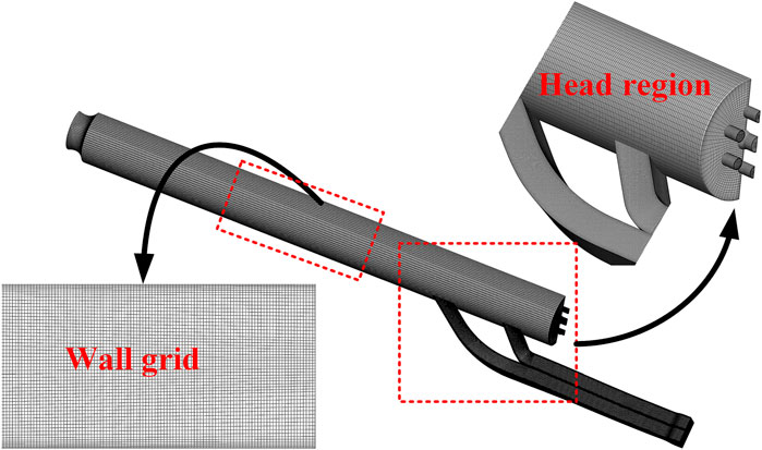
In order to reduce the calculation effort, the computational domain is half of the entire domain with the symmetry boundary conditions. The structured meshes are generated to improve the calculation accuracy. The meshes in the head region are dense because the flow structures and mixing effect in this region are complex. The structured meshes in the whole domain and some typical regions are displayed in Figure 6.
The computational domain and grid are generated using commercial software ANSYS ICEM 19.0. A multiblock grid approach is used (as shown in Figure 6). To ensure the accuracy of the numerical simulation, cells are densely close to the wall surface, the high-temperature exhaust inlet, and the powder inlet. The height of the first cell row is made a value of 0.1 mm near the wall, and the total number of cells is 0.9 million.
Grid Independence Analysis
In order to eliminate the influence of the grid sizes on the calculation results, three different mesh systems are built for the grid independence study, the grids are coarse, medium, and fine, and the number of grids is 0.26, 0.91, and 1.48 million, respectively. For different grid regimes, the concentration distribution of carbon dioxide on the section of the combustion chamber is compared. Figure 7 shows the concentration distribution of carbon dioxide at each interface of the combustor displayed by the three different grid regimes. The y-z cross section at x/l = 0.25 is selected from the location of the side wall air inlet mounted the combustion chamber, and the concentration value shows great fluctuation. Therefore, the carbon dioxide concentration in the cross section of the combustion chamber is significantly reduced after x/l = 0.25. From Figure 7, the calculated carbon dioxide concentration on the cross section by three grid systems is basically overlapping. The medium grid and fine grid are closer to each other at the separation point. In order to balance the calculation efficiency and accuracy, medium grid is used for subsequent calculation. The average value of y plus calculated on the grid wall is 22, which is set based on the requirement of the standard k-ε turbulence model.
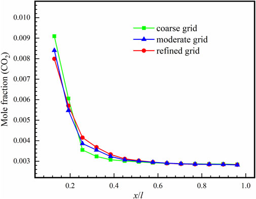
FIGURE 7. Averaged mole fraction of CO2 on y-z sections along the streamwise direction predicted by different grid regimes.
Results and Discussions
In order to study the influence of the head structures and high-temperature exhaust inlet patterns on the performance characteristics of the combustion chamber, the flow field characteristics, the mixing efficiency with the total pressure loss, and the density distribution of the combustion chamber are analyzed and compared.
Flow Field Characteristics
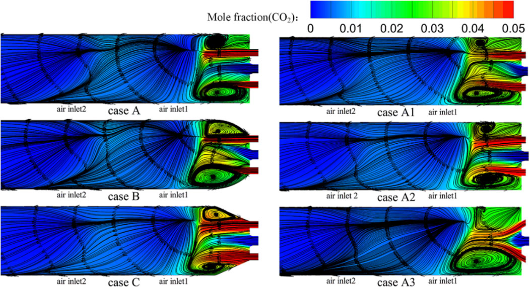
In order to figure out the flow field structures inside the combustion chamber in each design, the streamline distributions of the symmetry plane under various conditions are presented. Figure 8 shows the contours of the mole fraction (CO2) and streamline distributions on the x-z central sections of the combustion chamber in each case. The high-temperature exhaust at the inlet of the combustion chamber is water vapor and carbon dioxide, and the central fluidizing gas is air. It can be seen that the high-temperature exhaust mixes with the supplied air at air inlet 1 and air inlet 2 in each case, which forms a recirculation zone inside the head of the combustion chamber. In different cases, the scales of the recirculation zone are different. The small recirculation zones cause the powder to gather together and have a negative effect on the operation of the combustion chamber. Moreover, the powder cannot burn totally in the combustion chamber because of the short residence time so that the production of the powder combustion gathers inside the head of the combustion chamber. Compared with case A, case B and case C have similar symmetrical recirculation zones and the scale of the recirculation zones is relatively large, which can cover the powder injection region. In case B and case C, high-temperature exhaust and air are mixed to form a recirculation zone with a symmetrical structure in the head, which increases the stay time of the powder and can easily achieve fully burned. In case A, some metal powder is wrapped in the recirculation zone and cannot be transported to the core combustion region for full combustion. Compared with other cases, the high-temperature exhaust in case B and case C surrounds the powder particles closely to peel off the surface oxide layer and liquid film of the powder particles continuously, which helps the powder particles to burn completely. In case A2 and case A3, it can be seen that increasing the number of high-temperature exhaust inlets is helpful to the fluidization effect of the powder and the formation and extension of the recirculation zone. In case A3, it can be clearly seen that the heightened effect of the recirculation zone is obvious, and the scouring effect of high-temperature exhaust on the core reaction region is improved. When the exhaust and powder fuel are injected at high temperature with a certain angle, the mixing and combustion efficiency of powder and exhaust are stronger than other cases.
Contours of relative density of the mixing exhaust/air on two y-z sections (x/l = 0.125 and x = 0.25) for all the cases are displayed in Figure 9. The relative density is the ratio of the total density to the air density.
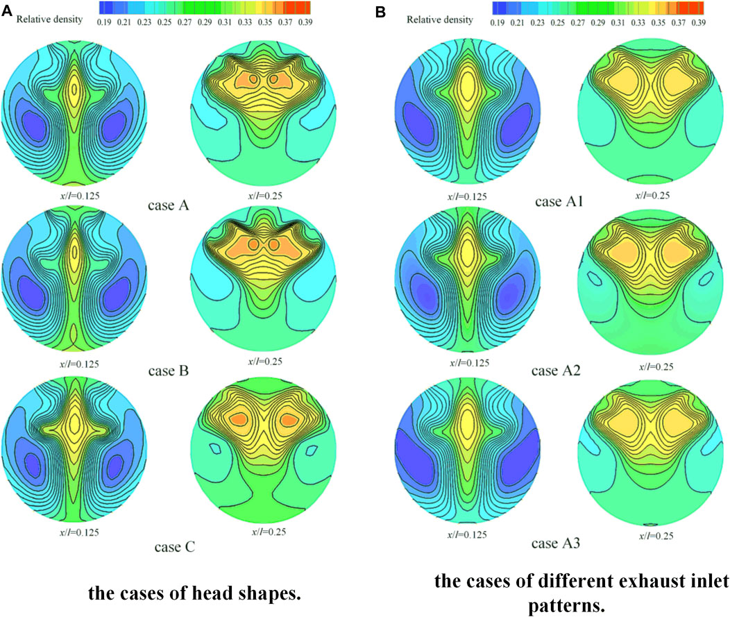
FIGURE 9. Contours of relative density of the mixing exhaust/air on two y-z sections (x/l = 0.125 and x = 0.25) for all the cases: (a) the cases of head shapes (case A, case B, and case C); (b) the cases of different inlet patterns (case A1, case A2, and case A3).
The high relative density is found on the middle of the cross section x/l = 0.125, and it also distributed two sides in the section of x/l = 0.25 for all cases. When the relative density of the certain area is close to 1, it indicates that the density of the area is close to the air. It also means that the mixing degree is better. And the relative density gradient describes the uniformity of the mixing field. From Figure 9A, the high relative density is found in small area inside cylindrical head and round head at the section of x/l = 0.25. It has disadvantages for the powder mixing with the gases around in the region. On the other side, the relative density distribution of the coned head is uniform with a good mixing efficiency. In addition, a better relative density is obtained in the case with the change of exhaust inlet patterns to the inclined six holes type. In the section of x/l = 0.125, a large region with relative high density is found in the coned head shape, which indicates that this design provides a better mixing performance than the other cases.
Pressure distributions on the x-y central sections and six y-z sections along the streamwise direction for all the cases are shown in Figure 10. A region with high static pressure is formed at the region of the two air side inlets. The high-pressure regions in case A and case B are larger than those in case C, which prevents the powder injection and mixing in the combustion chamber. The pressure loss is also shown in this figure, and the coned head type obtains the smallest pressure loss penalty. In case A1 and case A2, there is an obvious decrease in pressure inside the head region, but it is improved in case A3. Therefore, the inclined six holes type, that is, case A3, provides the best powder injection and mixing. Compared with case A1 and case A2, the pressure distribution in case A3 is more uniform.
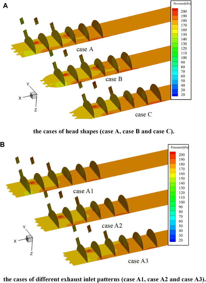
FIGURE 10. Pressure distributions on the x-y central sections and six y-z sections along the streamwise direction for all the cases: (a) the cases of head shapes (case A, case B, and case C); (b) the cases of different inlet patterns (case A1, case A2, and case A3).
Mixing Efficiency
In 1992, Lomkov and Kopchenov (Kopchenov and Lomkov, 1992) proposed the definition of a mixing degree in a certain section is defined as follows:
In the formula,
In this expression,
Figure 11 shows the comparisons of mixing efficiency distributions for all cases. Each datum is obtained by averaging all the results on the y-z sections along the streamwise direction. The side wall air inlet 1 and air inlet 2 cause additional flow mixing in the combustion chamber. The mixing effect is not obvious when the flow is approaching in the combustion chamber. Therefore, the starting point of the distribution in the combustion chamber is set at air inlet 2, and all the six distributions curves obtain the same trend. From Figure 11, the mixing efficiency of the process increases continuously in the section of the combustion chamber from air inlet 2. The final value is equal to 1, which means that the mixing efficiency in the combustion chamber gradually reaches the maximum value. However, in the entire flow field, the mixing efficiency of the coned type (case C) combustor shows an advantage at the starting region of the inlet 2 section. At the starting point, the mixing efficiency of the round type (case B) combustor is always lower than the mixing degree of other two cases. The curve of the round head type has presented a rapid increase in the considered range of x direction. This shows that the mixing efficiency of the round head is better than that of the cylindrical type. It can be seen that change in the number and angle of high-temperature exhaust inlets can have great influence on the mixing efficiency, when cases A1, A2, and A3 are compared. It is not obvious that by changing the head structures and the exhaust inlet patterns in the combustion chamber can directly affect the mixing efficiency. In addition, the relationship between pressure loss and mixing efficiency needs to be considered together to determine the mixing performance.
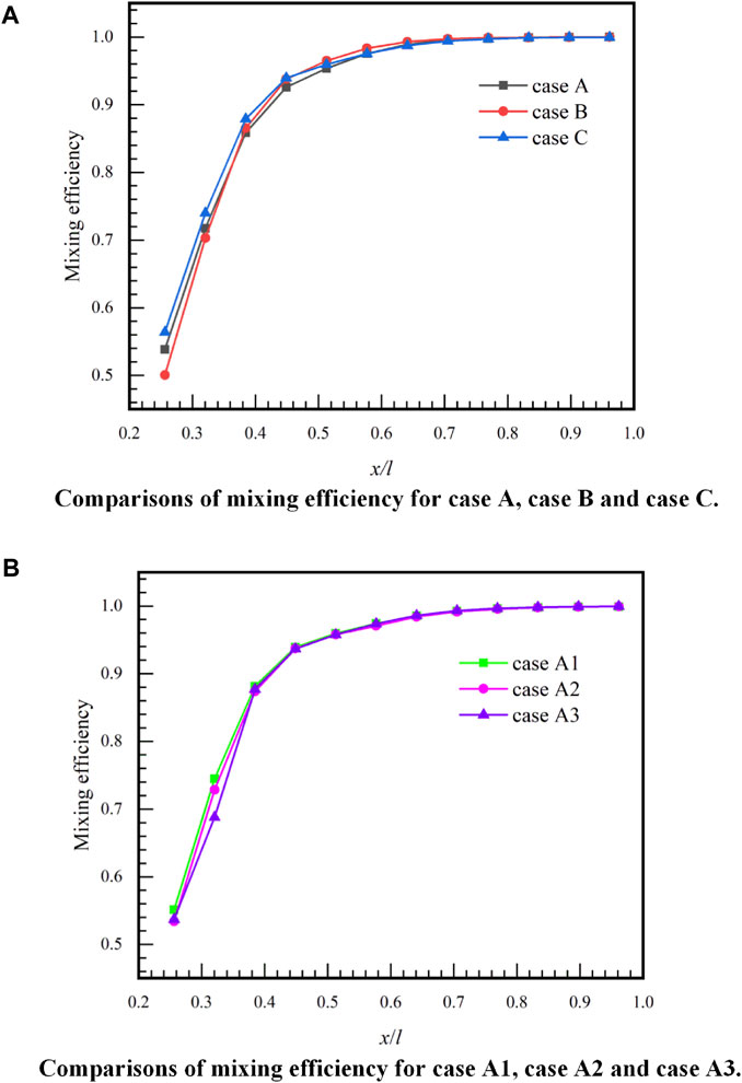
FIGURE 11. Comparisons of mixing efficiency distributions for all cases. Each datum is obtained by averaging all the results on the y-z sections along the streamwise direction. (a) Comparisons of pressure mixing efficiency for case A, case B, and case C. (b) Comparisons of pressure mixing efficiency for case A1, case A2, and case A3.
Figure 12 shows correlation between pressure recovery coefficients and mixing efficiency on the y-z sections along the streamwise direction. It can be seen from Figure 12 1) that the traditional cylindrical head of the combustion chamber gives more total pressure loss under the same mixing efficiency. At this time, the coned head type has improved this problem, and it always has high mixing efficiency than other types. This also indicates that the coned head type has the lowest pressure loss under the same mixing efficiency. It can be seen from Figure 12 2) that the three curves of mixing efficiency of case A1, case A2, and case A1 are nearly overlapping. When the head shapes are the round head or coned head, the total pressure loss and mixing efficiency are improved compared with the cylindrical head. In addition, from Figure 12A, it can be found that the round head is slightly inferior to the coned head. It can be seen from Figure 12 1) and Figure 12 2) that as long as the head shape is improved, there is obvious advantages in total pressure loss and mixing efficiency.
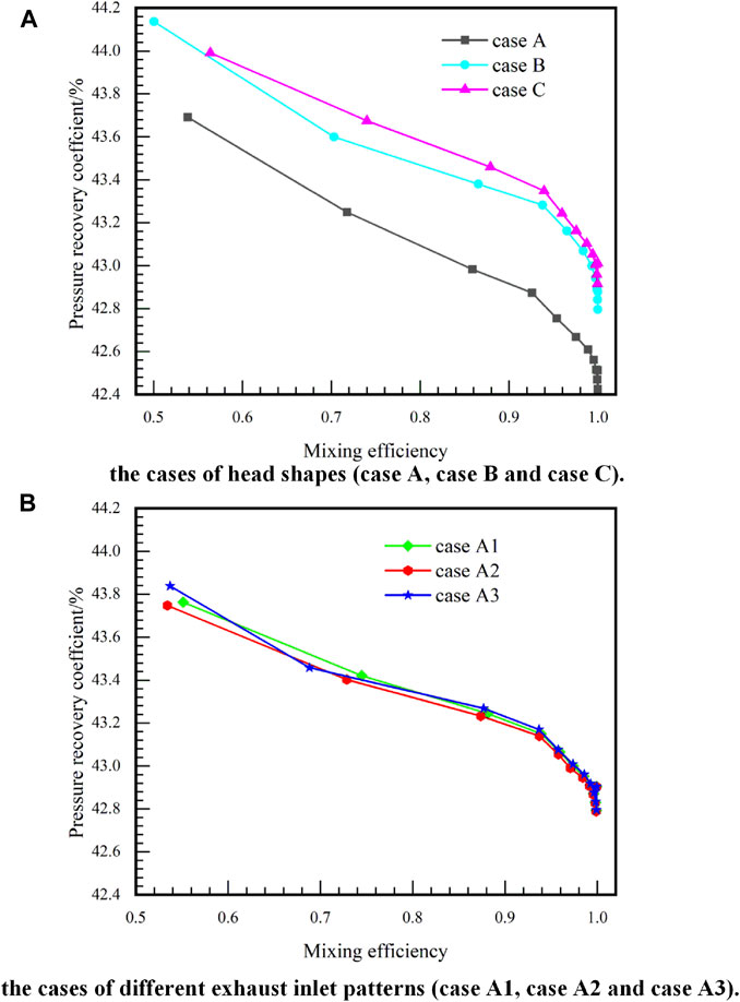
FIGURE 12. Correlation between pressure recovery coefficients and mixing efficiency on the y-z sections along the streamwise direction: (a) the cases of head shapes (case A, case B, and case C); (b) the cases of different exhaust inlet patterns (case A1, case A2, and case A3).
Pressure Loss
The pressure loss in the mixing process is an important evaluation factor for the structure design in a combustion chamber. In order to further compare the pressure loss of several cases and evaluate the engine performance, the pressure recovery coefficient in the combustion chamber is calculated.
The total pressure recovery coefficient is expressed as follows:
In the formula,
The total pressure recovery coefficient of the inlet is defined as: the ratio of the average total pressure of the inlet to the average total pressure of the undisturbed part. It is used to measure the pressure loss of the airflow inside the engine.
The average total pressure (Li et al. 2017) is defined as follows:
In the formula,
According to the total inlet pressure recovery coefficient, the pressure recovery coefficient of the combustion chamber is defined. The pressure recovery coefficient is defined as follows:
where
Figure 13 shows the pressure recovery coefficients distributions for all cases along the axial section. The six curves have the same trend, and the section pressure recovery coefficient shows a gradually decreased trend along the axial direction. It can be seen that the pressure recovery coefficient of case A is always lower than that of other cases in Figure 13A. Even compared with case A1, case A2, and case A3, the pressure recovery coefficient of case A is the smallest. It also indicates that the pressure loss of the combustion chamber with the modified head shapes and exhaust inlet patterns is smaller than that of case A. Among them, case C has the best performance with the largest pressure recovery coefficient compared with other configurations. Therefore, it is more recommended to use a round head or coned head type to improve mixing effect of powder and high temperature exhaust. When the number of high temperature exhaust inlets is changed, the effect of improving the pressure recovery coefficient is not too obvious. It can be clearly seen from Figure 13 that the cross-sectional pressure recovery coefficient in the final stage has increased. Because the cross section is located in front of the engine throat, the pressure recovery coefficient in this region is increased with the pressure increasing.
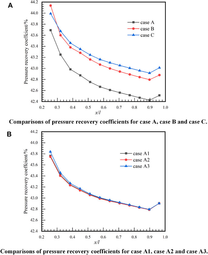
FIGURE 13. Pressure recovery coefficients distributions for all cases: (A) pressure recovery coefficients of different cases of the head shapes; (B) pressure recovery coefficients of different cases of the exhaust inlet patterns.
Summary and Conclusion
The k-ε standard turbulence model and the three-dimensional component transport model are used in this study, which is selected from a comprehensive turbulence model validation simulating the flow in the powder-fuel ramjet combustion chamber. Different head shapes of combustion chamber and exhaust inlet patterns are designed, aiming at improving the mixing of powder and exhaust in a combustion chamber. The characteristics and flow field structure of the combustion chamber in each case are compared and analyzed. The pressure recovery, mixing efficiency, and the relative density are presented and compared. The conclusions emerged from this study are provided as follows.
1 For the head shape of the combustion chamber, the design with the coned head (case C) and the round head (case B) has benefits in powder injection and mixing inside the combustion chamber compared with the cylindrical head (case A). The cylindrical head forms recirculation located in the corner of the combustion chamber, which easily leads to powder deposition in the head region and then reduces the powder combustion efficiency. However, the design with the coned head has a better mixing effect than the round head.
2 Compared with the cylindrical head, the mixing efficiency of the combustion chamber is improved without increasing the pressure loss penalty in the case of the cylindrical head and the coned head. The best mixing efficiency of the combustion chamber is obtained by the coned head case.
3 The exhaust inlet of eight-hole type (case A2) has advantages in the powder–exhaust mixing compared with the design with four-hole type (case A1) by increasing the area of the mixing region. Compared with the normal cylindrical holes, the inclined inlet injection holes (case A3) can generate stronger flow impingement and flow mixing in the core part of the chamber with reduced pressure loss penalty.
Data Availability Statement
The raw data supporting the conclusions of this article will be made available by the authors, without undue reservation.
Author Contributions
WX designed the research. MR processed the corresponding data. MR wrote the first draft of the manuscript. JL helped organize the manuscript. WX revised and edited the final version.
Funding
The research work is financially supported by the open cooperative innovation fund of Xi’an Modern Chemistry Research Institute (748030030) and the startup funds of Central South University (202045012).
Conflict of Interest
The authors declare that the research was conducted in the absence of any commercial or financial relationships that could be construed as a potential conflict of interest.
Publisher’s Note
All claims expressed in this article are solely those of the authors and do not necessarily represent those of their affiliated organizations, or those of the publisher, the editors, and the reviewers. Any product that may be evaluated in this article, or claim that may be made by its manufacturer, is not guaranteed or endorsed by the publisher.
Acknowledgments
This work was carried out at the School of Aeronautics and Astronautics at Central South University, China, and College of Astronautics, Nanjing University of Aeronautics and Astronautics China.
References
Abbud-Madrid, A., Modak, A., Branch, M. C., and Daily, J. W. (2001). Combustion of magnesium with carbon dioxide and carbon monoxide at low gravity. J. Propulsion Power 17 (4), 852–859. doi:10.2514/2.5816C
Abdalla, A. M., Hossain, S., Petra, P. M., Ghasemi, M., and Azad, A. K. (2020). Achievements and trends of solid oxide fuel cells in clean energy field: a perspective review. Front. Energ. 14 (2), 359–382. doi:10.1007/s11708-018-0546-2
Auerswald, S., Hoerberg, C., Pflug, T., Pfafferott, J., Bongs, C., and Henning, H. (2020). Experimental Investigation of the Air Exchange Effectiveness of Push-Pull Ventilation Devices. Energies 13 (21). doi:10.3390/en13215817
Bertin, J. J., and Cummings, R. M. (2003). Fifty years of hypersonics: where we've been, where we're going. Prog. Aerospace Sci. 39 (6-7), 511–536. doi:10.1016/s0376-0421(03)00079-4
Chelaru, T.-V., and Mingireanu, F. (2011). Hybrid rocket engine, theoretical model and experiment. Acta Astronautica 68, 1891–1902. doi:10.1016/j.actaastro.2010.12.008
Choudhury, P. R. (1982). Characteristics of a side dump gas generator ramjet. 18th AIAA/SAE/ASME Jt. Propulsion Conf. doi:10.2514/6.1982-1258
Chuang, C. L., Cherng, D. L., Hsieh, W., Settles, G., and Kuo, K. (1989). Study of flowfield structure in a simulated solid-propellant ducted rocket. 27th Aerospace Sci. Meet.
Clark, W. H. (1982). Experimental Investigation of pressure oscillations in a side dump ramjet combustor. J. Spacecraft Rockets 19 (1), 47–53. doi:10.2514/3.62203
Dijkstra, F., Mayer, A., Wilson, K., Smith, R., and Schadow, K. (1995). Ducted rocket combustion experiments at low gas-generator combustion temperatures. 31st AIAA/ASME/SAE/ASEE Jt. Propulsion Conf. Exhibit. doi:10.2514/6.1995-2415
Gaitonde, D. V. (2015). Progress in shock wave/boundary layer interactions. Prog. Aerospace Sci. 72, 80–99. doi:10.1016/j.paerosci.2014.09.002
Gany, A. (2015). Thermodynamic limitation on boron energy realization in ramjet propulsion. Acta Astronautica 98, 128–132.
Gong, L., Chen, X., Yang, H., Li, W., and Zhou, C. (2017). Investigation on the effect of diaphragm on the combustion characteristics of solid-fuel ramjet. Acta Astronautica 139, 449–462. doi:10.1016/j.actaastro.2017.07.031
Goroshin, S., Higgins, A. J., and Kamel, M. (2001). Powdered metals as fuel for hypersonic ramjets. ASEE Jt. Propulsion Conf. Exhibit. doi:10.2514/6.2001-3919
Goroshin, S., Higgins, A. J., and Lee, J. H. S. (1999). Powdered magnesium - carbon dioxide combustion for Mars propulsion. 35th AIAA/ASME/SAE/ASEE Jt. Propulsion Conf. Exhibit.
Hsieh, W. H., Chuang, C. L., Yang, A. S., Cherng, D. L., Yang, V., and Kuo, K. K. (1989). Measurement of flowfield in a simulated solid-propellant ducted rocket combustor using laser Doppler velocimetry. AIAA/ASME/SAE/ASEE 25th Jt. Propulsion Conf. doi:10.2514/6.1989-2789
Hsu, K. Y., Gross, L. P., Trump, D. D., and Roquemore, W. M. (1995). Performance of a trapped-vortex combustor. 33rd Aerospace Sci. Meet. Exhibit. doi:10.2514/6.1995-810
Huang, C., Yu, H., and Dai, J. (2020). Mixing and combustion augmentation of the RBCC with different mixer configurations in ejector mode. Acta Astronautica 174, 281–293.
Kopchenov, V. I., and Lomkov, K. E. (1992). The enhancement of the mixing and combustion processes in supersonic flow applied to scramjet engine. 28th AIAA/SAE/ASME/ASEE Jt. Propulsion Conf. Exhibit. doi:10.2514/6.1992-3428
Li, C., Hu, C., Xin, X., Li, Y., and Sun, H. (2016). Experimental study on the operation characteristics of aluminum powder fueled ramjet. Acta Astronautica 129, 74–81. doi:10.1016/j.actaastro.2016.08.032
Li, J., Liu, H., Liu, X., Ye, Y., Wang, H., Wang, X., et al. (2021). Development of a simplified n-heptane/methane model for high-pressure direct-injection natural gas marine engines. Front. Energ. 15 (2), 405–420. doi:10.1007/s11708-021-0718-3
Li, L.-q., Huang, W., Yan, L., and Li, S.-b. (2017). Parametric effect on the mixing of the combination of a hydrogen porthole with an air porthole in transverse gaseous injection flow fields. Acta Astronautica 139, 435–448. doi:10.1016/j.actaastro.2017.07.048
Li, X., Zhang, W., Huang, Z., Ju, D., Huang, L., Feng, M., et al. (2019). Pre-chamber turbulent jet ignition of methane/air mixtures with multiple orifices in a large bore constant volume chamber: effect of air-fuel equivalence ratio and pre-mixed pressure. Front. Energ. 13 (3), 483–493. doi:10.1007/s11708-019-0631-1
Linnell, J., and Miller, T. (2002). A preliminary design of a magnesium fueled Martian ramjet engine. 38th AIAA/ASME/SAE/ASEE Jt. Propulsion Conf. Exhibit. doi:10.2514/6.2002-3788
Liu, C., Sun, M., Wang, H., Yang, L., An, B., and Pan, Y. (2020). Ignition and flame stabilization characteristics in an ethylene-fueled scramjet combustor. Aerospace Sci. Tech. 106, 106186. doi:10.1016/j.ast.2020.106186
Liu, D., Chen, Y., and Dai, W. (2020). Acoustic Characteristics of Bi-directional Turbines for Thermoacoustic Generators. Front. Energ. 10 (2). doi:10.1007/s11708-020-0702-3
Miller, T., and Herr, J. (2004). Green rocket propulsion by reaction of Al and Mg powders and water. ASEE Jt. Propulsion Conf. Exhibit. doi:10.2514/6.2004-4037
Murty, M., and Chakraborty, D. (2012). Effect of injection angle in mixing and combustion characteristics of scramjet combustor. Int. J. Hypersonics 2, 15–28.
ONERA (2002). Ramjet Scramjet & PDE [EB/OL]. . http://www.onera, source of work.
Rashkovskiy, S. A. (2019). Formation of solid residues in combustion of boron-containing solid propellants. Acta Astronautica 158, 277–285. doi:10.1016/j.actaastro.2019.03.034
Ristori, A., Heid, G., Cochet, A., and Lavergne, G. (1999). Experimental and numerical study of turbulent flow inside a research SDR combustor. 35th AIAA/ASME/SAE/ASEE Jt. Propulsion Conf. Exhibit. doi:10.2514/6.1999-2814
Roe, P. L. (2003). Characteristic-based schemes for the Euler equations. Annu. Rev. Fluid Mech. 18 (1), 337–365.
Schadow, K. (1972). Boron combustion characteristics in ducted rockets. Combustion Sci. Tech. 5, 107–117. doi:10.1080/00102207208952511
Shafirovich, E., and Varma, A. (2008). Metal-CO2 propulsion for Mars missions: Current status and opportunities. J. Propulsion Power 24 (3), 385–394. doi:10.2514/1.32635
Shafirovich, E. Y., Shiryaev, A. A., and Goldshleger, U. I. (1993). Magnesium and carbon dioxide - A rocket propellant for Mars missions. J. Propulsion Power 9 (2), 197–203. doi:10.2514/3.23609
Singh, L. A., and Walker, M. L. R. (2015). A review of research in low earth orbit propellant collection. Prog. Aerospace Sci. 75, 15–25. doi:10.1016/j.paerosci.2015.03.001
Stowe, R. A., Dubois, C., Harris, P. G., Mayer, A. E. H. J., Dechamplain, A., and Ringuette, S. (2004). Performance prediction of a ducted rocket combustor using a simulated solid fuel. J. Propulsion Power 20, 936–944. doi:10.2514/1.2799
Stull, F. D., Craig, R. R., Streby, G. D., and Vanka, S. P. (1983). Investigation of a dual inlet side dump combustor using liquid fuel injection. AIAA 21st Aerospace Sci. Meet. doi:10.2514/6.1983-420
Vigot, C., Cochet, A., and Guin, C. (1991). Combustion behavior of boron-based solid propellants in a ducted rocket. Int. J. Energetic Mater. Chem Prop 2, 386–401. doi:10.1615/intjenergeticmaterialschemprop.v2.i1-6.230
Woosuk, J., Seungkwan, B., Juhyeon, P., and Sejin, K. (2018). Combustion characteristics of ramjet fuel grains with boron and aluminum additives. J. Propulsion Power 34, 1070–1079.
Xu, Y., Jia, R., Medina, H., and Sun, H. (2019). Effect of tangential swirl air inlet angle on the combustion efficiency of a hybrid powder-solid ramjet. Acta Astronautica 159, 87–95. doi:10.1016/j.actaastro.2019.03.046
Nomenclature
A area of the selected region (m2)
c mass concentration
D component mixing degree
d combustor diameter (mm)
d1 powder fuel inlet diameter (mm)
d2 high-temperature exhaust inlet diameter (mm)
h1 dome height 1 (mm)
h2 dome height 2 (mm)
k turbulent kinetic energy(m2/s2)
l combustor length (mm)
l1 length of air inlet 1 (mm)
l2 length of air inlet 2 (mm)
l3 the distance between the exhaust inlet with the fuel inlet (mm)
P0 total pressure (Pa)
R the net rate of production of species
S the rate of creation
u speed along the x axis (m/s)
v speed along the y axis (m/s)
w speed along the z axis (m/s)
x streamwise direction (m)
y spanwise direction (m)
z normal direction (m)
Greek symbols
α air inlet angles (°)
β angle between the high-temperature exhaust inlet and the fuel inlet (°)
γ angle between high-temperature exhaust inlet (°)
ε eddy current dissipation rate
η mixing efficiency
θ1 angle between air inlet 1 and combustion chamber (°)
θ2 angle between air inlet 2 and combustion chamber (°)
λ pressure recovery coefficient
μ fluid dynamic viscosity (Pa·s)
ρ fluid density (kg/m3)
σ total pressure recovery coefficient
ϕ angle of the cone head
Subscripts
0 total
in air inlet
max maximum
out outlet air flow
undisturbed undisturbed air flow
Keywords: powder ramjet engine, powder deposition, mixing, flow impingement, pressure loss
Citation: Xi W, Liu J and Mengfei R (2021) Improvement of Mixing Efficiency in the Combustion Chamber of a Powder-Fuel Ramjet Engine. Front. Energy Res. 9:756905. doi: 10.3389/fenrg.2021.756905
Received: 11 August 2021; Accepted: 01 September 2021;
Published: 06 October 2021.
Edited by:
Lei Luo, Harbin Institute of Technology, ChinaReviewed by:
Wei Huang, National University of Defense Technology, ChinaZhiyong Lin, Sun Yat-sen University, China
Copyright © 2021 Xi, Liu and Mengfei. This is an open-access article distributed under the terms of the Creative Commons Attribution License (CC BY). The use, distribution or reproduction in other forums is permitted, provided the original author(s) and the copyright owner(s) are credited and that the original publication in this journal is cited, in accordance with accepted academic practice. No use, distribution or reproduction is permitted which does not comply with these terms.
*Correspondence: Ren Mengfei, MTU2NTYyNzk4MzZAMTYzLmNvbQ==; Jian Liu, amlhbi5saXVAY3N1LmVkdS5jbg==
 Wenxiong Xi
 Jian Liu
 Ren Mengfei