 Shibin Luo1
 Zhichao Miao
 Jian Liu
 Wenxiong Xi
- 1School of Aeronautics and Astronautics, Central South University, Changsha, China
- 2College of Aerospace Science and Engineering, National University of Defense Technology, Changsha, China
As a promising and efficient active cooling method, double layer transpiration cooling is introduced into the design of the cooling system in the leading edge of a hypersonic vehicle. The physical model is built combined with hypersonic transpiration cooling, film cooling, heat conduction, porous media heat conduction and convection heat transfer. In addition, effects of different kinds of coolants are considered to reveal cooling mechanisms in different operation conditions. A comprehensive turbulence model validation and mesh independence study are provided. Flow characteristics caused by flow impingement, separation, transition and interaction with the cooling flows are displayed and analyzed in the work. When different kinds of coolants supplied at the same mass flow rate, the coolants with low densities, i.e., H2 and He, have the lowest peak temperature compared with the coolants with large densities, i.e., N2 and CO2. The coolants with low densities have a large ejecting velocity which provides large kinetic energy to penetrate deeply in the porous media. In addition, when the ejecting velocity is large enough, a recirculation is formed in front of the leading edge and pushes the high temperature region located in stagnation region away from the leading edge. However, when the coolants are ejected at the same velocity, the coolants with large densities exhibit better cooling performance.
Introduction
Continuous increase of flight Mach number of the hypersonic vehicle, the total temperature of the freestream increases and the surface aerodynamic heating of the aircraft is furtherly enhanced. To meet the aerodynamic performance, the sharp leading edge shape is adopted, which also leads to strong aerodynamic heating (Boyd & Padilla, 2003; Glass, 2008). The peak of heat flux density at the leading edge of a hypersonic vehicle can reach more than 10 MW/m2 (Kennedy et al., 2011). The high heat flux density imposed on the leading edge has exceeded the melting point of the materials and led to the damage to the structures. And with the development of hypersonic vehicles in the direction of wide speed range, long flight time, high Mach number, and lightweight, the traditional passive thermal protection technology is unable to meet high heat load (Ji et al., 2021). Therefore, it is urgent to search for an efficient active cooling technology to protect the leading edge and other high temperature regions of a hypersonic vehicle (Huang et al., 2015).
Transpiration cooling is a kind of active cooling technology that can greatly improve cooling efficiency with limited coolant supply which has the advantage of providing a large quantity of contacting surfaces for solid surfaces and coolant flows. The coolant enters the micro skeleton material of porous media and induces convective heat transfer which has benefits for heat transfer within the porous media. At the same time, a thin film is formed on the solid surface of the material when the coolant flow ejects out and isolates the protected surfaces from the high-temperature mainstream (Luikov, 1963; Glass et al., 2001). Compare with regenerative cooling and film cooling, transpiration cooling can improve respectively the cooling efficiency by 35 and 13% (Landis & Bowman, 1996; Leontiev, 1999). At the same time, transpiration cooling has the advantages of uniform film coverage, low coolant consumption, and high cooling efficiency (Dahmen et al., 2014). At present, transpiration cooling has been applied in the engine combustion chamber, rocket nozzle, nose cone, and leading edge of the reentry aircraft (Soller et al., 2009).
Scholars have carried out some experimental and numerical studies on the application of transpiration cooling in hypersonic vehicles. Shen et al. (2016) carried out transpiration cooling experiments using water as the coolant. The experimental results show that the cooling efficiency is the lowest in the stagnation zone where bears high aerodynamic heating and high stagnation pressure. Jiang et al. (2017) carried out an experimental study on the strut with three different cooling structures in a wind tunnel. The results show that single transpiration cooling structures cannot effectively cool the leading edge of the strut under high injection pressure. Also, the average efficiency of the combination of transpiration cooling and film cooling is higher than that of single transpiration cooling under the same coolant consumption. Connolly (2021) numerically studied the effects of geometric structures on hypersonic transpiration cooling performance under the condition of Ma = 7.5. The results show that the radius of the nosetip has a great influence on the heat flux, while the wedge angle has little effect on the heat flux on the wedge-shaped surface.
Ding et al. (2019) concentrated on the thermal protection of the leading edge of a hypersonic vehicle and proposed a coupled numerical method to calculate the overall cooling effect. Based on the previous studies about double layer cooling structures in a turbine blade, a novel double layer combined cooling (DLCC) conception is proposed by Ding et al. (2020). The coolant is allocated reasonably by adjusting the layout of the film slots, and the feasibility of the film-transpiration combined cooling scheme is verified. The work of Ding et al. (2020) shows that the double layer combined cooling is a very effective active cooling method, which provides a reference for the design of thermal protection system of a hypersonic vehicle. Ding et al. (2020) considered the effects of several discrete film slot layouts on cooling efficiency of the double layer combined cooling structures. The transpiration cooling efficiency is mainly determined by the properties of coolants and main flow, blowing ratio, the geometric structure, and mainstream conditions (Zhu et al., 2018). However, flow structures and heat transfer mechanism of double layer combined cooling conception need to be further studied.
In the previous study, Chauvin and Carter (1955) used gaseous Helium, gaseous Nitrogen, and distilled water as the coolants of transpiration cooling. The results show that the consumption of Helium is less than Nitrogen when the same cooling effect is achieved. Gülhan and Braun (2011) compared the cooling effects of Air, Argon, and Helium at the same blow ratio. The results show that the cooling efficiency of air and Argon is the same, and Helium has better cooling performance under the same blowing ratio.
In the present work, the novel double layer combined cooling structure and transpiration cooling technology is used in the leading edge cooling of a hypersonic vehicle. A model coupled with compressible flow, porous media heat transfer, convective heat transfer, and heat conduction are proposed. The heat transfer and fluid flow characteristics of the transpiration cooling are revealed. Effects of the different coolants and mainstream conditions are considered in this paper. Some suggestions are provided for the application of transpiration cooling in the leading edge of a hypersonic vehicle.
Description of the Computational Domain
Geometrical Model
The design of the geometric model in this work bases on the double layer combined cooling structure at the leading edge of a hypersonic vehicle proposed by Ding et al. (2020). The structure is composed of inner and outer layers, the outer layer is a transpiration cooling layer, and the porous medium material is sintered nickel-based superalloy.
The inner layer is a film slot layer with discrete slots, which is made of high-strength aluminum alloy. Part of the coolant can directly enter the porous media layer through the slots in the two sides, and some coolant can be directly ejected out of the leading edge through the central slot. The pipe at the tail continuously transports coolant into the cooling cavity to realize the thermal protection of the leading edge. The schematic diagram of the structure is shown in Figure 1.
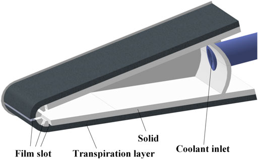
FIGURE 1. Double layer transpiration cooling in the leading edge of a hypersonic vehicle.
Because the leading edge shape and flow structure characteristics are the same along the spanwise direction, the two-dimensional geometric model is adopted ignoring the three-dimensional effect. In addition, the geometric model and flow field characteristics are symmetric in the spanwise direction, half of the sectional model is selected. The main size of the model is shown in Figure 2.
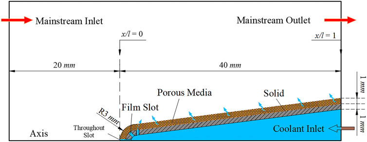
FIGURE 2. Two-dimensional computational domain used in the present study.
In Figure 2, the total length of the leading edge is 40 mm, the wedge angle is 14°, and the radius of the head is 3 mm. The film slot layer and the transpiration cooling layer have the same thickness of 1 mm, and the width of all the discrete slots is 0.5 mm.
The sharp end of the leading edge is the origin. The mainstream flow direction is taken as the positive direction of the x-axis, then the positive direction of the y-axis is determined.
Computational Domain and Physical Model
In this paper, the computational domain includes hypersonic transpiration cooling, film cooling, heat conduction in the porous media, and convective heat transfer is established. The computational domain is shown in Figure 3. Table 1 shows the governing equations of all the heat transfer processes (Ding et al., 2020).

FIGURE 3. Boundary conditions setting.
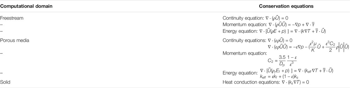
TABLE 1. Conservation equations for different computational domains (Ding et al., 2020).
In Figure 3, the coolant is injected from the inlet on the right side, and the mass flow rate is controlled as 0.03–0.05 kg/s. Part of the coolant is ejected out through a throughout slot in the central part and pushes the shock wave away from the outside surface. The other part enters the porous media through the film slot and penetrates through the porous media after fully heat exchange with the solid materials. Then a uniform coolant film forms on the solid surface which separates the high temperature mainstream from the structure surfaces.
Computational Method and Procedure
Meshing Details
The complete structured meshing of the geometric model is carried out, and the O-block and discrete block strategy are adopted to generate the structured meshes. Because the mesh quality of shock wave boundary layer and outside wall has a great influence on the calculation results, the mesh height of the first layer of the leading edge outside wall is adjusted so that the dimensionless wall y plus value is less than one on the whole outside wall (She and Fan, 2018).
In the contact region of the film slot, porous media, and mainstream are connected by coupled algorithms to realize data transportation. The local details of the meshes are shown in Figure 4.
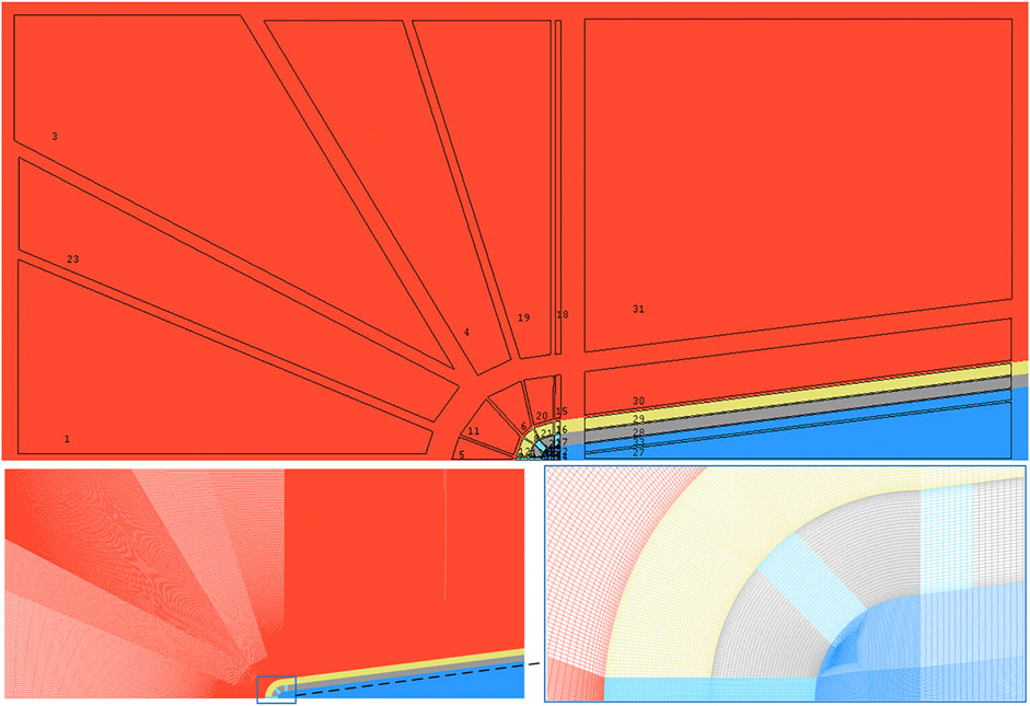
FIGURE 4. Structured meshes and local mesh details.
A mesh independence study is performed at mass flow rate of 0.03 kg/s. For the mesh independence study, four kinds of mesh with different numbers of nodes, mesh 1 (284,393), mesh 2 (337,832), mesh 3 (403,417), and mesh 4 (549,667), are generated to calculate the stagnation point temperature of the outside wall. The results calculated by the four kinds of mesh are 2328.0, 2321.6, 2314.2, 2319.1 K. Set the Mesh 3 (Total nodes = 403,417) as the baseline. The percentage error of Mesh 1, Mesh 2, and Mesh 4 are +0.6%, +0.32%, and -0.21%, respectively.
According to the calculation results, it can be seen that with the increase of the mesh volume, the difference between the stagnation temperature for different mesh systems becomes smaller. In addition, Mesh 3 is closer to the mainstream temperature and is selected for the lateral calculations.
Boundary Conditions and Solver
The boundary conditions are shown in Table 2 setting according to the experimental data in references (Shen et al., 2016; Ding et al., 2020) to provide some conveniences for turbulence model validations.

TABLE 2. Boundary conditions.
The inlet of the main flow and the upper boundary of the calculation domain is set as pressure far-field, and the outlet of the main flow is set as pressure outlet. The inlet of the coolant is set as mass flow inlet, and the lower boundary of the calculation domain is set as symmetry. The Mach number of the supersonic mainstream is 4.2 with a total pressure of 1.33 MPa and a total temperature of 2310 K. The coolant inlet is set as a constant velocity or mass flow inlet with a flow rate of 0.03–0.05 kg/s, respectively. The temperature of the coolant is set as 300 K. The porosity of porous media is 0.33 and the viscous resistance is 1.33e+13. The turbulent intensity and viscosity ratio are set respectively as 5% and 10.
The air density of mainstream adopts the ideal gas model and viscosity determined by the Sutherland law. The specific heat, thermal conductivity data of air are obtained from the NIST database and fitted with polynomial functions of temperature (He et al., 2020).
A suitable turbulence model is very important for calculation of complex turbulent flows (Dong et al., 2018). The RANS k-ω SST turbulence model is suitable for complex boundary layer and separation flows. Density-based solver and implicit formulation are applied. Second-order upwind scheme is used for the discretization of the continuity, momentum, and energy equations.
The convergence of the calculation is judged by the three aspects below:
1) The absolute criteria are set as 10−5 for the continuity, x-velocity, y-velocity, energy, k, and ω items.
2) Mass conservation between the inlet and the outlet in the computational domain.
3) The difference of averaged temperature and pressure on the outside wall of the leading edge is less than 0.1% between two iteration steps.
Turbulence Model Validation
To validate the accuracy of the computation model, the experiments in Reference (Ding et al., 2020) is used for validation. The size diagram of the test model is shown in Figure 5, and the boundary conditions are set the same with the reference (Ding et al., 2020). The temperature of the outside surface of the porous media is extracted and compared with the experimental results shown in Figure 5. Three common turbulence models, i.e., k-ε RNG model, k-ε Reliable model and k-ω SST model, are used for comparisons with the experimental data. It is found that the numerical simulation results predicted by the k-ω SST model are basically consistent with the experimental data in the literature with better treatment of the shear effect of the boundary layer. Other turbulence models fail to obtain good results and have a large percentage error with experimental values. The trend of the calculated result by the k-ω SST model and experimental result also has good agreements although some deviations can be found in the transition regions. The difference of peak temperature between the calculated results and experimental results is only 29.3K (2.3%). Therefore, the k-ω SST model used in this paper has enough accuracy.
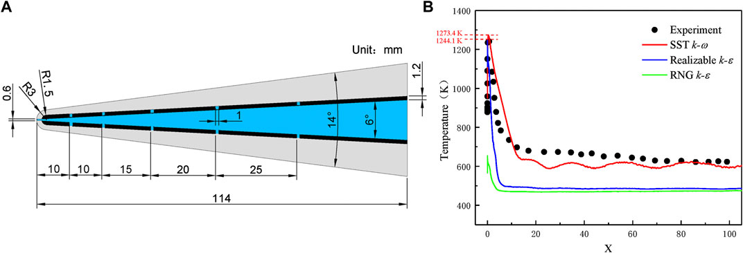
FIGURE 5. Turbulence model validation. (A) The tested model in Ref. (Ding et al., 2020). (B) Comparisons of temperature distribution along the leading edge.
Results and Discussion
Effects of Different Kinds of Coolants at Same Mass Flow Rate
Figure 6 shows the whole field temperature contours using different kinds of coolants when the mass flow rate of the coolant inlet is set as 0.03–0.05 kg/s. Four kinds of coolants, i.e., CO2, N2, He, and H2 are used, respectively. From the figure, high temperature is found in the region with strong flow impingement and shear flows. With the strong disturbance with the mainstream, bow-shock is formed around the leading edge. After the shock, the temperature is raised around the leading edge and the stagnation region can reach the total temperature of the mainstream. With the coolant ejects from the porous media in the leading edge and temperature of the leading edge is decreased. In the double layer cooling system, the temperature is also decreased along the streamwise direction. However, different kinds of coolants show different cooling abilities even at the same mass flow rate. It can be shown that the coolants with small density have better temperature distribution especially at approaching the stagnation region. It can be attributed to the higher ejecting velocity is obtained by the coolants with smaller density at the same mass flow rate. The coolants are arranged from high density to low density in one column. When the coolant mass flow rate at 0.03–0.05 kg/s, the cooling ability of different kinds of coolant is in the order of CO2 < N2 < He < H2.
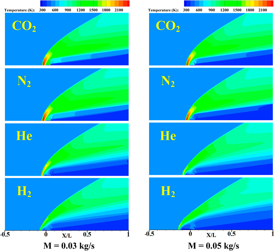
FIGURE 6. Temperature distributions of the whole domain at coolant mass flow rate = 0.03 kg/s and 0.05 kg/s.
According to Eq. 1, when the mass flow rate of coolant is constant, the flow velocity is inversely proportional to the density of the fluid. The densities of the four kinds of coolants, i.e., CO2, H2, He and N2, are 1.797, 0.082, 0.163 and 1.138 kg/m3, respectively. Under the same mass flow rate, the velocity of the gas with lower density is faster, the bow shock wave is pushed farther away from the head, and an obvious reversed flow region is formed at the stagnation region, which can greatly reduce the temperature.
Figure 7 shows the x-velocity and streamlines around the leading edge with different cooling gases at M = 0.03 kg/s and M = 0.05 kg/s. The x-velocity also reflects the bow shock generation in the leading edge and has a close correlation with static temperature of the mainstream. The small x-velocity means the high static temperature in this region, such as the stagnation region. From the streamline distribution, the strong flow separation and shear flow can be found in the leading edge. When the coolant ejects the cooling hole in the leading edge, the cooling flow interacts with mainstream and is pushed on the leading edge and forms a layer of cooling film. In addition, when the coolant flow ejects at a large velocity, a recirculation region exists in the leading edge region because of the pressure difference and has better thermal protection for the stagnation region. The recirculation region forms a low velocity region and prevents the high temperature mainstream from intruding inside of the leading edge. The largest recirculation region is found in the case of H2 at the larger mass flow rate of M = 0.05 kg/s.
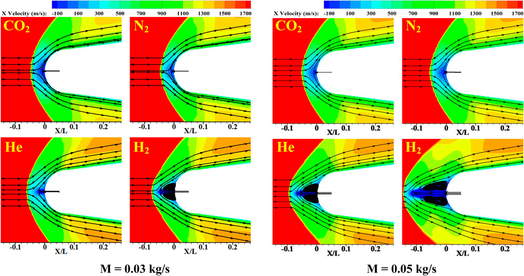
FIGURE 7. x-velocity distribution and streamlines around the leading edge.
Figure 8A displays temperature distributions on the leading edge surface for different kinds of coolants at M = 0.03 kg/s and M = 0.05 kg/s. Overall, the temperature on the leading edge surfaces is much lower compared with the mainstream temperature nearby because of the cooling film formed around the leading edge which prevents high thermal load. From the figure, the highest temperature on the leading edge is found in the region close to the stagnation region. Because a straight cooling hole is arranged in the head, the temperature of the leading edge corresponding to the stagnation region is not the highest. When the surface temperature reaches the highest point and it begins to decrease along the streamwise direction and becomes relatively stable after some developments along the streamwise direction. The highest temperature of the leading edge is obtained by the case of CO2 and the peak temperature is obtained in the order of TCO2 > TN2 > THe > TH2. The phenomenon also has good agreements with the cooling ability in Figure 6. The highest peak temperature obtained by the case of CO2 is 1262.2 K and the lowest temperature is obtained by the case of H2 with a temperature below than 600 K. The reason for this phenomenon is the larger ejecting velocity and heat capacity of H2. With the increase of the coolant mass flow rate, the temperature on the leading edge surface is also decreased.
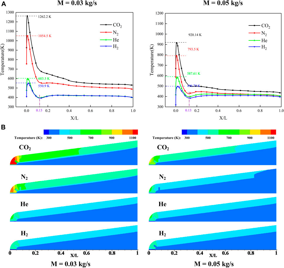
FIGURE 8. Temperature for different kinds of coolants at M = 0.03 kg/s and M = 0.05 kg/s. (A) Temperature contours of the leading edge region (B) Temperature distributions along the leading edge surfaces.
Temperature contours of the leading edge region for different kinds of coolants at M = 0.03 kg/s and M = 0.05 kg/s are displayed in Figure 8B. The high temperature is found in the regions close to the stagnation regions where the coolants have difficulties being ejected out. The temperature distribution has the trend of decrease along the streamwise direction and decreases from the inner to the outside. The sharp increase of temperature is found in the region close to the stagnation region and quickly decreases by the cooling effect. From the temperature distribution, it can be noted that double layer transpiration cooling has a great effect on lower down the overall temperature of the leading edge.
Figure 9 presents mass fractions of coolant in the computational domain at different mass flow rates. From the figure, the coolant entering the cooling chamber and ejects out from the stagnation region of the leading edge. When the coolants eject out and form a cooling film along the leading edge surfaces, the coolants spread downstream along the porous media region driven by the pressure differences. It is found that the mass fraction of coolant downstream of porous media is N2 > He > H2 > CO2. The penetration into the porous media is related to the viscosity of the coolant which determines the flow pattern of coolant around the leading edge.
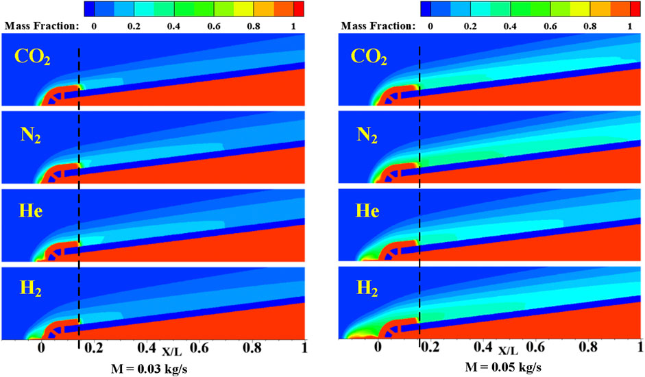
FIGURE 9. Coolants mass fraction distributions in the computational domain at different mass.
Effects of Different Kinds of Coolants at the Same Inlet Velocity
When the mass flow rate is constant, the ejecting velocity of different coolants is quite different. In the present study, effects of different kinds of coolants at the same inlet velocity are also considered in this paper. Cooling performance of the coolants at the same injection velocity, i.e., 2.7 m/s are compared. The velocity is chosen based on the case of N2 at the mass flow rate of 0.03 kg/s. Temperature contours for the whole domain using different coolants are provided in Figure 10. In the figure, four coolants, i.e., CO2, N2, He, and H2 are used. From the figure, the temperature contours inside the leading edge are similar for all the cases. The solid region of the leading edge is well protected by the coolants. The coolants penetrate into the porous media and decrease local temperature. However, in the case of CO2 and N2, the mass flow rates are much larger than the cases of He and H2 at the same injection velocity. At an inlet velocity of 2.7 m/s, the overall temperature is lower than 900 K in the downstream regions of the leading edge.

FIGURE 10. Temperature contours for different kinds of coolants at the same inlet velocity.
Figure 11 displays x-velocity contours and streamlines around the leading edge for different kinds of coolants at the same coolant inlet velocity. From the figure, the streamwise clearly presents the bow shock generation and development around the leading edge. Cooling film interacts with the mainstream and protects the surface of the leading edge. In some regions, reversed flows can be found in the head of the leading edge for the cases of CO2 and N2 which have large densities. Also, it can be found that the coolants penetrate deeply in the downstream porous media in the cases of CO2 and N2 when the coolants have a large density. The coolants with large densities have more strong momentum energy to eject out from the cooling holes and penetrate from the porous media.
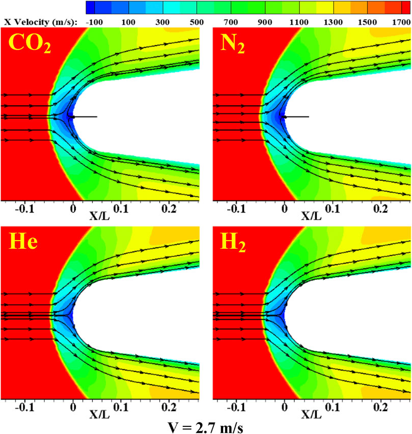
FIGURE 11. Streamwise velocity and streamlines around the leading edge for different kinds of coolants at the same inlet velocity.
Temperatures contours of the leading edge for different coolants are provided in Figure 12A. From the figure, the case of N2 and H2 has the lowest temperature in the head of the leading edge. For the whole leading edge, the cases of CO2 and N2 has relatively low temperature and the coolants have deep penetration downstream. The high density coolants have obvious strengthens when coolants are ejected at the same velocity. However, a relatively large temperature region is found for the case of CO2.
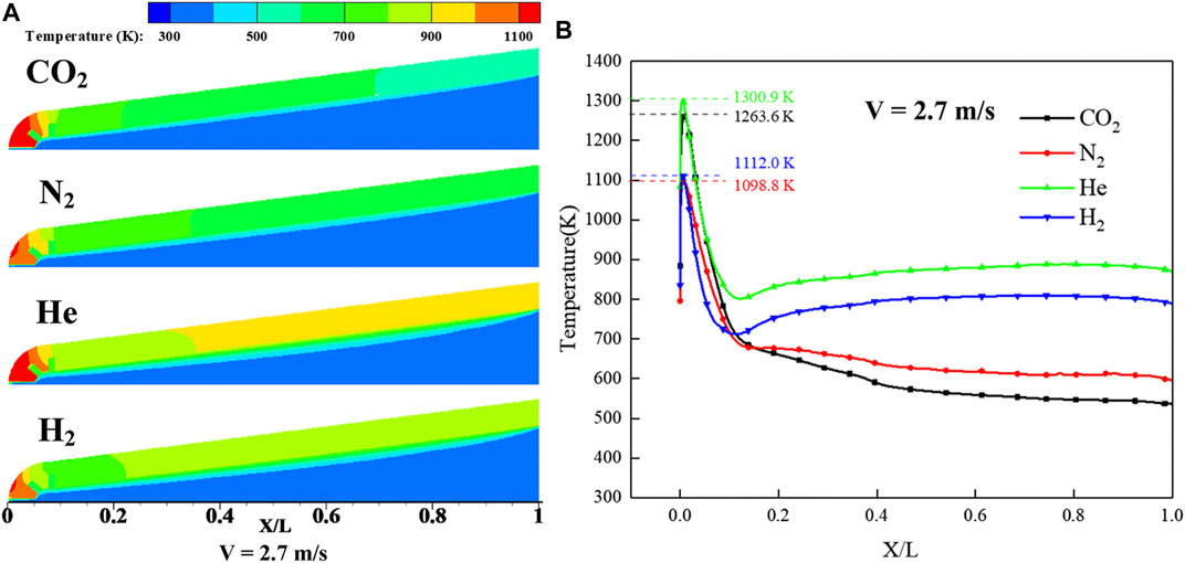
FIGURE 12. Temperature for different kinds of coolants at the same inlet velocity. (A) Temperature contours of the leading edge (B) Temperature distributions along the leading edge.
Figure 12B presents temperature distributions along the leading edge surface at the same coolant inlet velocity. From the figure, the trend of temperature is basically consistent with the results at the same mass flow rate. For the cases with different coolants, the peak temperature of the case of N2 as the coolant is the lowest. Considering the surface temperature of the whole porous medium regions, the best cooling performance is also provided by coolants using N2. For the cases of H2 and He, the peak temperature is more than 1250 K. The case of CO2 also shows good cooling performance in the downstream region and the surface temperature decreases faster after the peak temperature. However, in the case of CO2, the head region of the leading edge is relatively high. The worst cooling performance is provided by the case of He. Overall, the coolants with large densities have better cooling performance when coolants are ejected at the same velocity.
Figure 13A presents mass fractions distributions of coolant in the computational domain at the same inlet velocity. From the figure, it is clearly shown that the coolants with large densities, i.e., CO2 and N2, penetrate deeply in the porous media. The coolants are mainly concentrated in the leading edge region where the cooling holes are located. The mass fraction of in the cases of CO2 and N2 in the calculation domain is higher than that case of H2 and He. Figure 13B presents pressure distributions around the leading edge at the same inlet velocity. The pressure in the cooling chamber is large to ensure the coolant can eject out from the porous media in the leading edge region. However, the cases of CO2 and N2 are little larger than that of H2 and N2. The coolant in the cases of H2 and He are concentrated upstream of porous media and spread less downstream. However, the cases of CO2 and N2 distribute more coolants downstream of porous media which causes the downstream temperature of CO2 and N2 lower than that of H2 and He. The phenomenon is consistent with that founded in Figure 12.
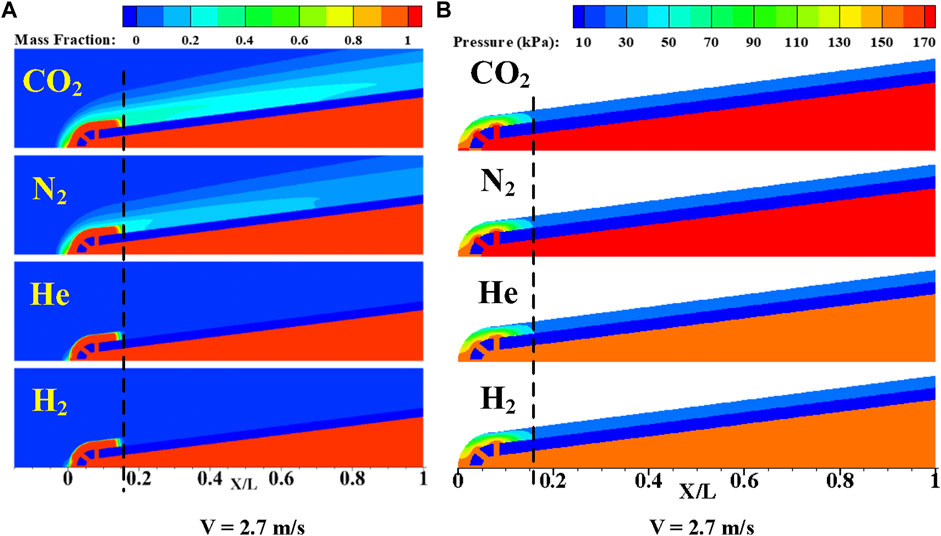
FIGURE 13. Pressure and mass fraction contours at the same inlet velocity. (A) Coolants mass fraction distributions in the computational domain. (B) Pressure contours in the leading edge for different kinds of coolants.
Conclusion
In the present work, the novel double layer combined cooling structure and transpiration cooling technology is used for the leading edge cooling of a hypersonic vehicle. The physical model built combining with compressible flow, porous media heat transfer, convective heat transfer, and heat conduction are proposed. Heat transfer and fluid flow characteristics of double layer transpiration cooling system are analyzed and revealed. The effects of the coolants and mainstream conditions are considered in this paper. Some conclusions can be obtained from the work.
1) For different kinds of coolants supplied at the same mass flow rate, the coolants with low densities, i.e., H2 and He, have the lowest peak temperature compared with the coolants with large densities, i.e., N2 and CO2. The coolants with low densities have large eject velocity which provides large kinetic energy to eject out from the leading edge and penetrates deeply in the porous media which well cooling protection downstream. In addition, when the ejecting velocity is large enough, a recirculation which is formed in front of the leading edge pushes the high temperature region located in stagnation regions away from the leading edge.
2) For different kinds of coolants supplied at the ejecting velocity, the coolants with large densities, i.e., CO2 and N2, provide good cooling performance considering the whole leading edge region. Compared with the coolant of CO2, the coolant of N2 can protect the leading edge better which has a lower temperature in the stagnation region.
Data Availability Statement
The original contributions presented in the study are included in the article/Supplementary Material, further inquiries can be directed to the corresponding author.
Author Contributions
SL, ZM, and JL provide research ideas and write the original manuscript. ZM carried out all the calculation work. JS, WX, and CL are responsible for the revision of the paper.
Funding
The research work is financially supported by the start-up funds of Central South University (202045012).
Conflict of Interest
The authors declare that the research was conducted in the absence of any commercial or financial relationships that could be construed as a potential conflict of interest.
Publisher’s Note
All claims expressed in this article are solely those of the authors and do not necessarily represent those of their affiliated organizations, or those of the publisher, the editors and the reviewers. Any product that may be evaluated in this article, or claim that may be made by its manufacturer, is not guaranteed or endorsed by the publisher.
Acknowledgments
This work was supported by the School of Aeronautics and Astronautics, Central South University.
Abbreviations
M, mass flow rate, kg/s; l, length of the leading edge, m; k, thermal conductivity, W/m·K; T, temperature, K; p, pressure, Pa; Dp, average pore diameter, m; K, permeability of porous media, m−2; U, velocity, m/s; x, y, Cartesian coordinate, m; μ, fluid dynamic viscosity, Pa·s; ρ, fluid density, kg/m3; k, thermal conductivity, W/(m.K); ε, porosity; γ, specific heat capacity ratio; 0, stagnation; f, fluid; s, solid; c, coolant; eff, effective; Ma, Mach number
References
Boyd, I., and Padilla, J. (2003). “Simulation of Sharp Leading Edge Aerothermodynamics,” in 12th AIAA International Space Planes and Hypersonic Systems and Technologies (Norfolk, Virginia: American Institute of Aeronautics and Astronautics). doi:10.2514/6.2003-7062
Chauvin, L. T., and Carter, H. S. (1955). Exploratory Tests of Transpiration Cooling on a Porous 8 Degree Cone at M= 2.05 Using Nitrogen Gas, Helium Gas, and Water as the Coolants. NACA Res. Memorandum, L55C29.
Connolly, J. (2021). “Geometry Dependence of Transpiration Cooling for Hypersonic Systems,” in AIAA Scitech 2021 Forum (VIRTUAL EVENT: American Institute of Aeronautics and Astronautics) (Reston, Virginia, USA: AIAA). doi:10.2514/6.2021-1519
Dahmen, W., Gotzen, T., Müller, S., and Rom, M. (2014). Numerical Simulation of Transpiration Cooling through Porous Material. Int. J. Numer. Meth. Fluids 76, 331–365. doi:10.1002/fld.3935
Ding, R., Wang, J., He, F., Dong, G., and Tang, L. (2019). Numerical Investigation on the Performances of Porous Matrix with Transpiration and Film Cooling. Appl. Therm. Eng. 146, 422–431. doi:10.1016/j.applthermaleng.2018.09.134
Ding, R., Wang, J., He, F., Wang, M., Luan, Y., Dong, G., et al. (2020). Numerical Investigation on a Double Layer Combined Cooling Structure for Aerodynamic Heat Control of Hypersonic Vehicle Leading Edge. Appl. Therm. Eng. 169, 114949. doi:10.1016/j.applthermaleng.2020.114949
Dong, X., Zhang, Z., Liu, D., Tian, Z., and Chen, G. (2018). Numerical Investigation of the Effect of Grids and Turbulence Models on Critical Heat Flux in a Vertical Pipe. Front. Energ. Res. 6, 58. doi:10.3389/fenrg.2018.00058
Glass, D. (2008). “Ceramic Matrix Composite (CMC) Thermal Protection Systems (TPS) and Hot Structures for Hypersonic Vehicles,” in 15th AIAA International Space Planes and Hypersonic Systems and Technologies Conference (Dayton, Ohio: American Institute of Aeronautics and Astronautics). doi:10.2514/6.2008-2682
Glass, D. E., Dilley, A. D., and Kelly, H. N. (2001). Numerical Analysis of Convection/Transpiration Cooling. J. Spacecraft Rockets 38, 15–20. doi:10.2514/2.3666
Gülhan, A., and Braun, S. (2011). An Experimental Study on the Efficiency of Transpiration Cooling in Laminar and Turbulent Hypersonic Flows. Exp. Fluids 50, 509–525. doi:10.1007/s00348-010-0945-6
He, F., Wu, N., Ran, F., and Wang, J. (2020). Numerical Investigation on the Transpiration Cooling of Three-Dimensional Hypersonic Inlet. Aerospace Sci. Technol. 106, 106152. doi:10.1016/j.ast.2020.106152
Huang, Z., Xiong, Y.-B., Liu, Y.-Q., Jiang, P.-X., and Zhu, Y.-H. (2015). Experimental Investigation of Full-Coverage Effusion Cooling through Perforated Flat Plates. Appl. Therm. Eng. 76, 76–85. doi:10.1016/j.applthermaleng.2014.11.056
Ji, Z., Qin, J., Cheng, K., Liu, H., Zhang, S., and Dong, P. (2021). Design and Performance of a Compact Air-Breathing Jet Hybrid-Electric Engine Coupled with Solid Oxide Fuel Cells. Front. Energ. Res. 8, 613205. doi:10.3389/fenrg.2020.613205
Jiang, P.-X., Huang, G., Zhu, Y., Liao, Z., and Huang, Z. (2017). Experimental Investigation of Combined Transpiration and Film Cooling for Sintered Metal Porous Struts. Int. J. Heat Mass Transfer 108, 232–243. doi:10.1016/j.ijheatmasstransfer.2016.12.014
Kennedy, P., Donbar, J., Trelewicz, J., Gouldstone, C., and Longtin, J. (2011). “Heat Flux Measurements in a Scramjet Combustor Using Direct Write Technology,” in 17th AIAA International Space Planes and Hypersonic Systems and Technologies Conference (San Francisco, California: American Institute of Aeronautics and Astronautics). doi:10.2514/6.2011-2330
Landis, J., and Bowman, W. (1996). “Numerical Study of a Transpiration Cooled Rocket Nozzle,” in 32nd Joint Propulsion Conference and Exhibit (Lake Buena Vista, FL, U.S.A.: American Institute of Aeronautics and Astronautics). doi:10.2514/6.1996-2580
Leontiev, A. I. (1999). Heat and Mass Transfer Problems for Film Cooling. J. Heat Transfer 121, 509–527. doi:10.1115/1.2826012
Luikov, A. V. (1963). Heat and Mass Transfer with Transpiration Cooling. Int. J. Heat Mass Transfer 6, 559–570. doi:10.1016/0017-9310(63)90013-9
She, L., and Fan, G. (2018). Numerical Simulation of Flow and Heat Transfer Characteristics of CuO-Water Nanofluids in a Flat Tube. Front. Energ. Res. 6, 57. doi:10.3389/fenrg.2018.00057
Shen, L., Wang, J., Dong, W., Pu, J., Peng, J., Qu, D., et al. (2016). An Experimental Investigation on Transpiration Cooling with Phase Change under Supersonic Condition. Appl. Therm. Eng. 105, 549–556. doi:10.1016/j.applthermaleng.2016.03.039
Soller, S., Kirchberger, C., Kuhn, M., Langener, T., Bouchez, M., and Steelant, J. (2009). “Experimental Investigation of Cooling Techniques and Materials for Highspeed Flight Propulsion Systems,” in 16th AIAA/DLR/DGLR International Space Planes and Hypersonic Systems and Technologies Conference (Bremen, Germany: American Institute of Aeronautics and Astronautics). doi:10.2514/6.2009-7374
Keywords: transpiration cooling, hypersonic vehicle, leading edge, recirculation, cooling performance
Citation: Luo S, Miao Z, Liu J, Song J, Xi W and Liu C (2021) Effects of Coolants of Double Layer Transpiration Cooling System in the Leading Edge of a Hypersonic Vehicle. Front. Energy Res. 9:756820. doi: 10.3389/fenrg.2021.756820
Received: 11 August 2021; Accepted: 30 August 2021;
Published: 09 September 2021.
Edited by:
Lei Luo, Harbin Institute of Technology, ChinaCopyright © 2021 Luo, Miao, Liu, Song, Xi and Liu. This is an open-access article distributed under the terms of the Creative Commons Attribution License (CC BY). The use, distribution or reproduction in other forums is permitted, provided the original author(s) and the copyright owner(s) are credited and that the original publication in this journal is cited, in accordance with accepted academic practice. No use, distribution or reproduction is permitted which does not comply with these terms.
*Correspondence: Jian Liu, jian.liu@csu.edu.cn