 Rui Zhang1,2
 Wenxiong Xi
- 1School of Aeronautics and Astronautics, Central South University, Changsha, China
- 2Airforce Aviation Repair Institute of Technology, Changsha, China
- 3Academy of Hi-Tech Research, Hunan Institute of Traffic Engineering, Hengyang, China
For a certain configuration of ablative pulsed plasma thruster, changing the initial energy is an effective way to optimize the performance of the thruster. Different energy supply methods will not only affect the macro discharge characteristics and system performance of the thruster, but also affect the micro characteristics of the plasma in the discharge channel, the equivalent parameters of the discharge circuit, energy conversion efficiency and so on. In this study, the discharge characteristics, ablation characteristics and plasma motion characteristics of the thruster under different energy supply methods are analyzed experimentally and theoretically. The results show that using the method which includes increasing capacitance to heighten the initial energy of system under the same voltage, using a low-voltage, large-capacitor power supply method under the same initial energy, can effectively increase the impulse generated by Lorentz force and its proportion in the impulse bit. Moreover, the proportion of the ablative propellant effectively ionized and accelerated by Lorentz force increases. Therefore, the thruster has higher specific impulse and efficiency.
Introduction
The Ablative Pulsed Plasma Thruster (APPT) has the advantages of small impulse, high specific impulse, and simple structure (Lemmer, 2017). It is especially suitable for position holding, resistance compensation, formation flight, and other space flight missions on small satellite (Huang et al., 2015; Silnikov et al., 2015). However, the propellant utilization and system efficiency seriously restrict the improvement of APPT performance and affect its application (Wu and Sun, 2018; Huang et al., 2020).
The discharge energy of the thruster is an important factor which affects the performance of the APPT system. Kazeev and Antropov et al. found out the specific impulse and system efficiency of the APPT can be greatly improved by increasing system discharge energy (Kazeev et al., 2002; Antropov et al., 2003). Benson and Arrington et al. found that the impulse bit and specific impulse of the thruster increase along with the increasing of the discharge energy, but the increase of discharge energy only has limited effect on improving the performance of the APPT system. High initial energy not only requires a more complex power supply, making the system more complex, but also aggravates the ablation of the thruster electrode and spark plug, affecting the service life of the thruster (Arrington et al., 1997; Rezaeiha et al., 2011). Nawaz et al. discussed the relationship between capacitance and inductance of the APPT according to the theory and experimental research. They found out under specific disposal conditions, the performance of the thruster can be optimized (Nawaz et al., 2010; Schönherr et al., 2010). Wu Zhiwen et al. studied the energy distribution of APPT to find the ways to reduce the energy loss, and a double-discharge APPT was designed to improve the efficiency of the thrusters (Huang et al., 2018; Wu et al., 2018). Wu Jianjun et al. found that increasing discharge energy can effectively improve the ionization degree of ablative propellant and the speed of plasma, high ionization and high velocity plasma produce larger impulse (Ou et al., 2018), (Zhang et al., 2020), (Zhang et al., 2013), (Wu et al., 2020a). For APPT with fixed configuration, improving initial energy level of the thruster is a possible and effective way to increase efficiency of the thruster.
Different energy supply methods will not only affect the discharge characteristics and system performance of the thruster, but also affect the plasma characteristics, equivalent parameters of the discharge circuit, energy conversion efficiency and other micro characteristics (Cheng et al., 2017; Sun et al., 2019). Although researchers have done a lot of research, its internal mechanism has not been fully grasped, so it is still difficult to improve the performance of the thruster. In order to understand the influence of different power supply methods on APPT performance, the discharge characteristics and system performance of APPT under different initial voltages, different capacitance, and different capacitance and voltage configurations at the same energy level are studied.
Experimental Setup and Method
Thrutser and Vacuum Chamber
The experimental setup was schematically given in Figure 1. A breech-fed parallel plate APPT was used in the experiment. The size of nonoxide copper electrode of the thruster was 35 × 15 × 3 mm3, and the distance between anode and cathode was 45 mm. Polytetrafluoroethylene (PTEE) was used as solid propellant and its ablative exposed surface was 45 mm long and 15 mm wide. A semiconductor spark plug was used as a discharge-inducing device which was mounted on the cathode. Four 3 μF polyester film capacitors were connected in parallel as energy storage device, and the capacitance was changed by changing the number of capacitor nC which was used. As shown in Figure 1, the thruster was placed inside a cylinder shape vacuum chamber which was used to simulate the space environment, whose working pressure was 3 × 10⁻³ Pa during testing.
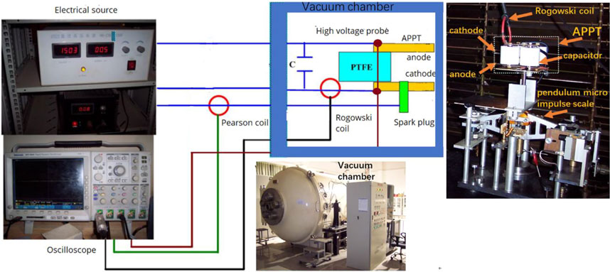
FIGURE 1. Schematic of the experimental set-up.
Discharge Circuit Parameters
Tek P5100 high voltage probe was used to measure discharge voltage, and CWT150 Rogowski coil was used to measure discharge current. Each measurement signal was collected by Tek DPO4034 four-channel oscilloscope.
The discharge circuit of APPT can be equivalent to an inductor-capacitor-resistor (LCR) circuit (Wu et al., 2020b), shown in Figure 2A. C is the capacitance, RC and LC are the equivalent resistance and equivalent inductance of the main capacitor respectively. Rt1 and Rt2 are the resistance transmission line to the electrode, Lt1 and Lt2 are the inductance of the transmission line to electrode, Rp and Lp are equivalent plasma resistance and inductance. Lext and Rext are the inductance and resistance of the external circuit. Lext is the sum of LC, Lt1, Lt2, Rext is the sum of RC, Rt1, Rt2.
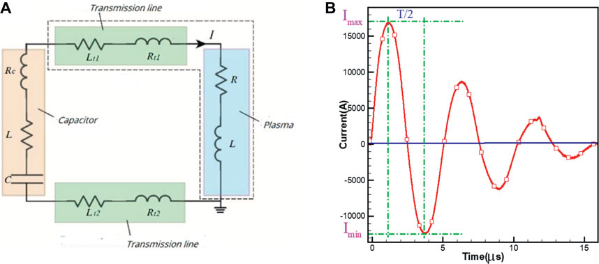
FIGURE 2. (A) Equivalent circuit diagram and (B) typical discharge current waveform of APPT.
As shown in Figure 2B, the main discharge current waveform of APPT oscillates is in the form of damped sine wave. By fitting the waveform, the equivalent resistance Req, inductance Leq and other important parameters of the discharge circuit can be obtained as
Leq is the sum of Lext, Lp, Req is the sum of Rext, Rp. Where T is the discharge cycle, Imax is the maximum value of the discharge current, Imin the minimum value of the discharge current.
By using the measurement method in Ref. (Koizumi et al., 2004), Lext, Rext and inductance gradient of electrode L’ can be obtained.
Performance Parameters
A pendulum micro impulse scale was used to measure the impulse bit Ibit. The construction and theory of the pendulum micro impulse scale can refer to Ref. (Zhang et al., 2016). The impulse bit of APPT is the sum of the impulse which is generated by aerodynamic force Igas plus the impulse which is generated by Lorentz force IEM. The Ibit can be expressed as
The IEM produced by the Lorentz force FEM can be obtained as (Pottinger et al., 2011)
Ψ is time integral value of the square of current I(t)
β is ratio of the impulse which is generated by the Lorentz force to the impulse bit, which can be expressed as
Ibit also can be expressed as
Where α is proportion of the ablated propellant which is accelerated by the Lorentz force, Cgas is movement speed of the ablated propellant accelerated by the aerodynamic force.
Four double Langmuir probes with a bias voltage of 27V were placed in the APPT plume area on axis of the thruster at 8, 12, 16 and 20 cm away from exposure face of the propellant. The plasma velocity Vp was measured by time-of-flight method (Myers et al., 1996).
The XS205DU electronic scale was used to weigh the mass change of propellant after 5400 times of discharge. Single-pulse ablation of propellant mass, mbit, can be calculated by the average. System specific impulse Isp. The efficiency η can be obtained as
Average velocity of the ablative propellant Ve can be obtained as
Experimental Results and Discussion
Effect of Different Initial Voltages on System Performance
There are Four capacitors are connected in parallel. In peace with the increasing of charging voltage from 1052 to 2031V, the initial energy of thruster increases from 7.09 to 24.74J.
Figure 3 shows APPT discharge current and voltage waveforms measured at different initial voltages. The waveforms in the figure are the average values of 10 measurements. By adopting formulas given in Discharge Circuit Parameters, discharge circuit parameters which are listed in Table 1 can be obtained.
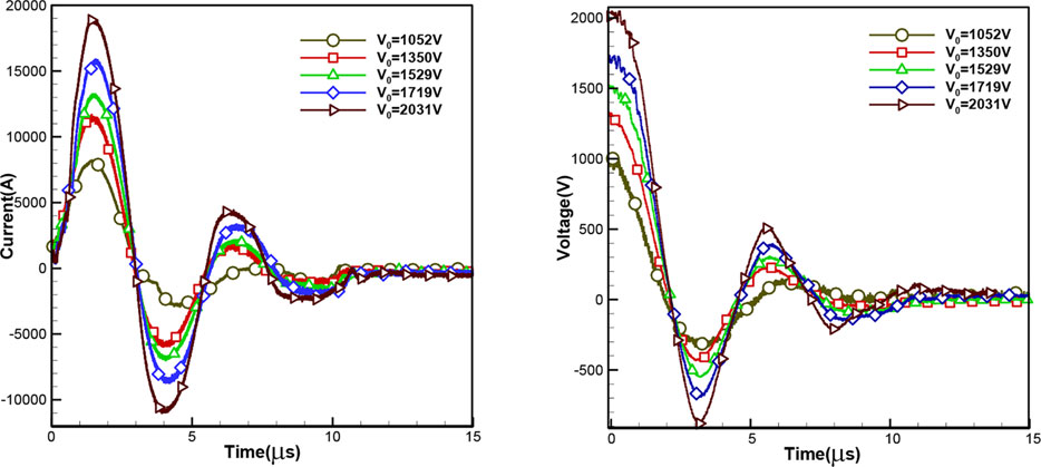
FIGURE 3. APPT discharge waveforms at different initial voltages.
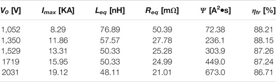
TABLE 1. APPT discharge circuit parameter at different initial voltages.
As we can see, E0 increases with the increasing of discharge voltage. The more energy is transferred to the discharge channel in a single discharge process, the more ablative propellant ionized, and provide energy for plasma acceleration. Furthermore, as Ψ increases from 72.38 A2•s to 673 A2•s, the impulse generated by Lorentz force increases, which is conducive to the acceleration of plasma. However, it’s worth noting that high initial voltage promotes the generation of highly ionized plasma (Gatsonis et al., 2002), because the highly ionized plasma reduces the plasma resistance in the discharge channel and, Req decreases with the increase of discharge voltage, resulting in ηtr reduced from 88.21 to 86.71%. Low discharge energy transfer efficiency at high initial voltage will cause more energy consumption in the external circuit which goes against improving system efficiency.
As Table 2 shows, both mbit and mbit/E0 increase with the increase of initial voltage. This means more energy is needed to further ionize additional ablated propellant, which is not conducive to performance improvement of the thruster (Keidar et al., 2004).

TABLE 2. Ablation characteristics of propellant at different initial voltages.
As shown in Table 3 and Figure 4, in pace with the increasing of the initial voltage, both IEM and Igas increase and, Ibit increases from 84.56 μN-s to 589.46 μN-s. The specific impulse increases from 458.97 to 627.85 s and, thruster efficiency increases from 2.7 to 6.81%. It can be seen that APPT system performance is improved with the increasing of initial voltage.
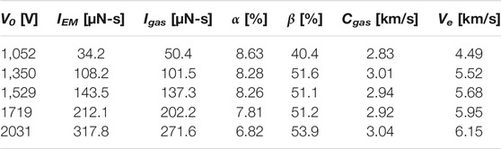
TABLE 3. APPT performance parameters at different initial voltages.

FIGURE 4. APPT thruster performances at different initial voltages.
With the increase of voltage, β increases from 40.4 to 53.9%, the ratio of the impulse generated by Lorentz force to the impulse bit increases. Vp (as shown in Figure 5), Cgas, Ve all increase accordingly. However, α decreases with the increase of initial voltage, which means that the proportion of the ablative propellant accelerated by aerodynamic force increases. Low-speed ablative propellant which is accelerated by aerodynamic force is not conducive to the ionization and acceleration because it contributes little to the system thrust (Wu et al., 2018). This is an adverse factor that will affect the utilization efficiency of propellant and the improvement of system efficiency. It can also be seen from Figure 4 that with the increasing of voltage, the specific impulse and efficiency growth rate of the thruster show a trend of gradual slowing down.
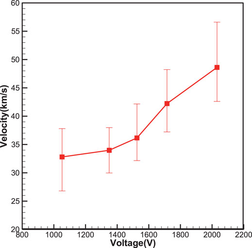
FIGURE 5. Plasma movement velocity of APPT at different initial voltages.
Effect of Different Capacitances on System Performance
The capacitor charging voltage is maintained at 1500V. By adjusting the number of parallel-connected capacitors, the capacitance increases from 3 to 12 μF. The initial discharge energy increases correspondingly. As Figure 6 shows, the discharge cycle of the thruster increases gradually and, Imax increases from 6.27 KA to 13.31 KA.
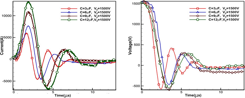
FIGURE 6. Discharge waveforms of APPT at different capacitances.
As shown in Table 4, under the influence of connection method and number of the parallel-connected capacitors, Leq, Req, and ηtr show a non-monotonic trend of change. With the increase of capacitance, Ψ increases from 49.81 A2•s at 3μF to 303.9 A2•s at 12 μF and, single capacitor discharge current square integral average value Ψ/nc also increases. Since the Lorentz force is proportional to the square integral of the current, the average Lorentz force that produced by a single capacitor increases.
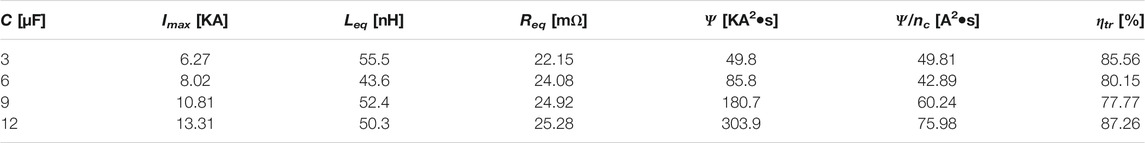
TABLE 4. APPT discharge parameters at different capacitances.
As shown in Table 5, with the increase of capacitance, mbit increases from 28.2 to 50.8 μg. Compared with the way of increasing the initial energy by increasing the initial voltage, mbit/E0 decreases accordingly, which is beneficial to improve the utilization and ionization of the propellant (Keidar et al., 2004).

TABLE 5. Ablation characteristics of propellant at different capacitances.
As shown in Table 6, as the capacitance increases, α also increases from 2.91 to 7.81%. This means that more ablative propellants are effectively ionized and accelerated by Lorentz force, which is a beneficial factor for improving propellant utilization and system efficiency. Figure 7 and Figure 8 show that performance parameters such as system efficiency, specific impulse, impulse bit, and plasma velocity all increase with the increase of capacitance. In particular, the impulse, specific impulse, and efficiency parameters all show a trend of rapid increase in slope. It seems that the performance of the thruster system can be improved more effectively by increasing the capacitance to increase the initial energy of the system.
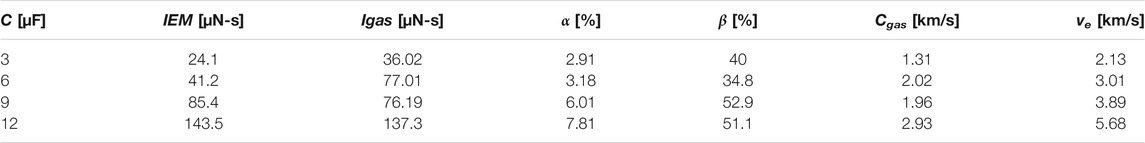
TABLE 6. APPT performance parameters at different capacitances.
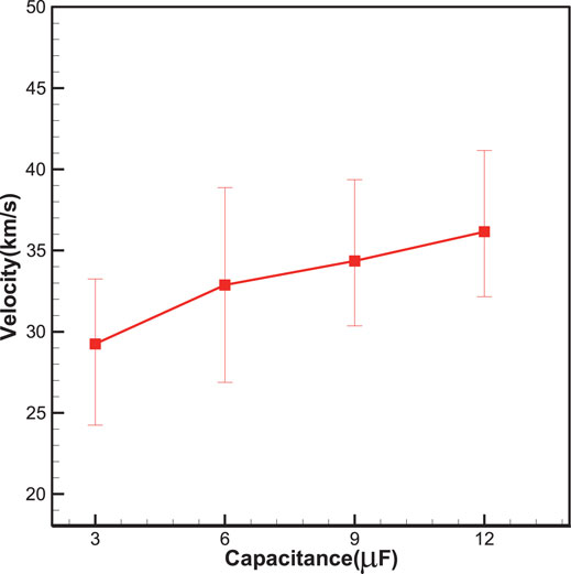
FIGURE 7. APPT plasma movement velocities at different capacitances.
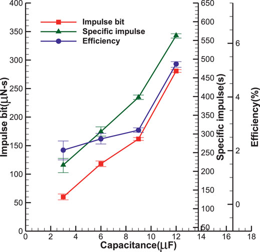
FIGURE 8. APPT system performances at different capacitances.
Performance of the APPT System at the Same Energy Level but With Different Capacitance and Voltage Configurations
This section focuses on the APPT system performance under the same initial energy (E0 = 6J), with different capacitance (C = 3, 6, 9, 12 μF), and different voltage configurations. As Figure 9 shown, in the low-capacitance, high-voltage configuration, the discharge cycle is shorter, the peak value and current rise steepness of the discharge current are larger, and the energy stored in the capacitor is released in a shorter time.
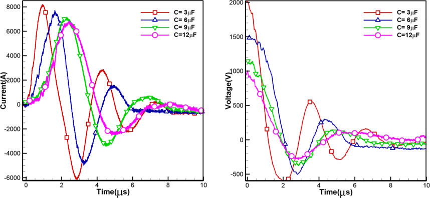
FIGURE 9. Discharge waveforms of APPT under different capacitance and voltage configurations (E0 = 6J).
Figure 10A shows the plasma density of the APPT plume which is measured by a current-model triple Langmuir probe. The construction and theory of a triple Langmuir probe can refer to Ref. (Gatsonis et al., 2004). Large peak current produces high-density plasma which causes the peak of plasma density increases from 6.98×10¹⁹ m−3 at 12μF to 1.39×10²⁰ m−3 at 3 μF. Additionally, as shown in Table 7 and Figure 10B, the value of Ψ and Ψ/nc are larger which means not only the Lorentz force but also the average Lorentz force produced by a single capacitor increase, and the plasma velocity is relatively high.
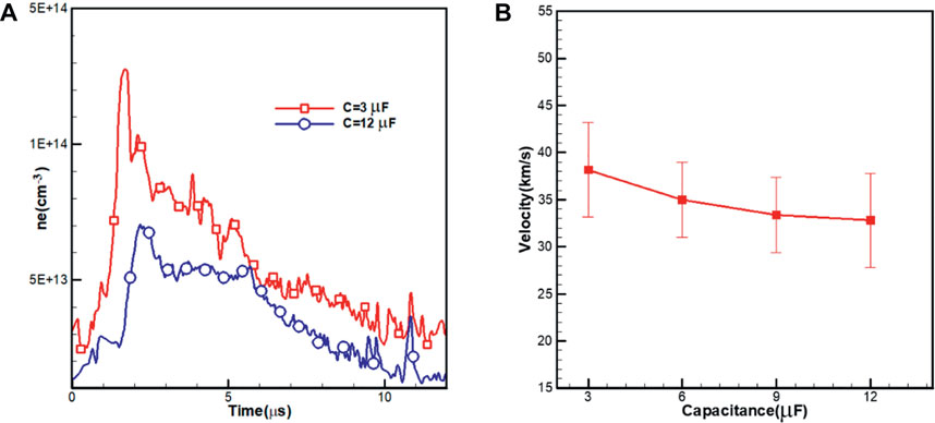
FIGURE 10. Plasma characteristics under different capacitance and voltage configurations, (A) plasma electron density, and (B) plasma velocity.
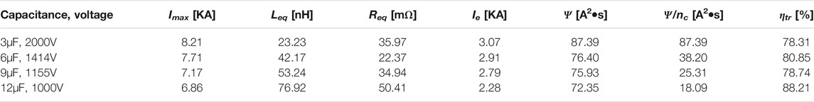
TABLE 7. Parameters of APPT discharge circuit with different capacitance and voltage configurations.
By normalizing the discharge current waveform, as shown in Figure 11, when the initial energy remains the same, the APPT discharge current oscillation intensifies under the condition of low capacitance and high voltage. The reverse discharge current will not only affect the service life of the capacitor, but will also cause “re-striking” on the surface of the propellant, and it will aggravate the ablation of the propellant (Spanjers et al., 1998). As shown in Table 8, the mass of ablative propellant is 3 times when the 3 μF capacitor is charged to 2000V of the 12 μF capacitor when it is charged to 1000V. Also, mbit/Ψ and mbit/E0 value increase as the decrease of capacitance. Therefore, under the same initial energy condition, the large capacitance and low voltage configuration can be more effective to reduce the ablation of the propellant and improve the utilization efficiency of the propellant.
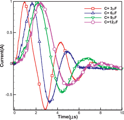
FIGURE 11. Normalized discharge current waveform.
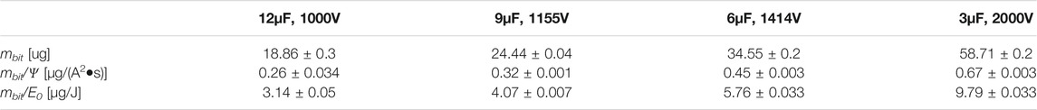
TABLE 8. Ablation characteristics of propellant under different capacitance and voltage configurations.
As shown in Table 9, as capacitance increases, IEM decreases from 41.3 μN-s to 34.2 μN-s and, Igas decreases from 74.3 μN-s to 50.4 μN-s. Vp, Cgas, and Ve also decrease accordingly. APPT with low capacitance and high voltage configuration has a relatively higher impulse bit. However, it’s worthless because β decreases from 40.4% at 12μF to 35.7% at 3 μF and, α decreases from 8.63 to 1.84%. The proportion of impulse which is generated by Lorentz force and the proportion of ablative propellant which is accelerated by Lorentz force both decrease with the increase of capacitance. Therefore, as shown in Figure 12, although APPT has a higher impulse bit under low capacitance and high voltage configuration, the specific impulse and system efficiency of the thruster decrease as the capacitance decreases.
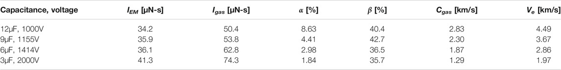
TABLE 9. APPT performance parameters under different capacitance and voltage configurations.
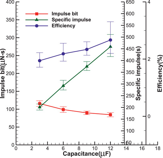
FIGURE 12. APPT thruster performances under different capacitance and voltage configurations.
Conclusion
In this paper, the discharge characteristics, propellant ablation characteristics, and system performance of APPT under different energy supply methods are systematically studied. By fitting and estimating the parameters of the APPT discharge circuit and system performance under various working conditions, the internal mechanism of how each parameter change affects the performance of the thruster is obtained.
1) Under a certain capacitance, with the increasing of discharge voltage, the plasma velocity, the impulse bit, the specific impulse, and the efficiency of the thruster all increase, and the system performance improves. However, in peace with the increasing of voltage, the efficiency of the system energy conversion to discharge energy decreases. While the mass of the ablative propellant increasing, the proportion of the ablative propellant which is effectively ionized and accelerated by the Lorentz force decreases, and the proportion of the ablative propellant which is accelerated by the aerodynamic force increases. This is not conducive to the performance improvement of the thruster. It can be concluded that simply increasing the initial voltage of the thruster has certain limitations on optimizing thruster performance.
2) At a given voltage, by increasing the capacitance can also improve system performance. Although the mass of the ablative propellant increases with the increasing of the capacitance, the mass of propellant ablated per unit energy decreases. Meanwhile, the ratio of impulse which is generated by Lorentz force to impulse bit, and the ablative propellant which is effectively ionized and accelerated by the Lorentz force increase. The thruster can obtain a better system performance by increasing APPT capacitance to increase the initial energy of the thruster.
3) Under the same initial energy with low capacitance and high voltage conditions, APPT has higher plasma density and velocity, larger discharge current square integral value and average single capacitor discharge current square integral value, which is conducive to the acceleration of the ablative propellant, so that APPT has higher impulse bit. However, in this case, the mass of the single-pulse ablative propellant is larger, and the ablative propellant which is accelerated by the Lorentz force and the proportion of impulse which is generated by Lorentz force in the impulse bit is relatively small. Therefore, the thruster specific impulse and system efficiency are the lowest.
Data Availability Statement
The original contributions presented in the study are included in the article/supplementary material, further inquiries can be directed to the corresponding author.
Author Contributions
ZR is responsible for the analysis of test data and the writing of articles, XW is responsible for the design of experiments and project guidance, and HQ is responsible for the implementation of experiments.
Funding
The Research Foundation of Education Bureau of Hunan Province, China (grant number 19C0009).
Conflict of Interest
The authors declare that the research was conducted in the absence of any commercial or financial relationships that could be construed as a potential conflict of interest.
Publisher’s Note
All claims expressed in this article are solely those of the authors and do not necessarily represent those of their affiliated organizations, or those of the publisher, the editors and the reviewers. Any product that may be evaluated in this article, or claim that may be made by its manufacturer, is not guaranteed or endorsed by the publisher.
References
Antropov, N., Diakonov, G., and Orlov, M. (2003). Development and Refinement of Highly Efficient 150J APPT, 28th International Electric Propulsion Conference, IEPC 03-061. Toulouse: France.
Arrington, L. A., Haag, T. W., and Pencil, E. J., (1997). A Performance Comparison of Pulsed Plasma Thruster Electrode Configurations. 25th International Electric Propulsion Conference. Cleveland, Ohio: IEPC-97-127.
Cheng, L., Ding, W., and Wang, Y. (2017). Preliminary Study on Discharge Characteristics in a Capillary Discharge Based Pulsed Plasma Thruster for, the 35th International Electric Propulsion Conference, IEPC-2017-433. USA: Georgia Institute of Technology.
Gatsonis, N. A., Byrne, L. T., Zwahlen, J. C., Pencil, E. J., and Kamhawi, H. (2004). Current-Mode Triple and Quadruple Langmuir Probe Methods with Applications to Flowing Pulsed Plasmas. IEEE Trans. Plasma Sci. 32 (5), 2118–2129. doi:10.1109/tps.2004.835520
Gatsonis, N. A., Zwahlen, J. C., and Wheelock, A. (2002). Characterization of a Pulsed Plasma Thruster Plume Using a Quaruple Langmuir Probe Methode. 38th AIAA/ASME/SAE/ASEE Joint Propulsion Conference and Exhibit. Indianapolis, Indiana: AIAA. 2002-4123.
Huang, T., Wu, Z., Liu, X., Xie, K., Wang, N., and Cheng, Y. (2015). Study of breakdown in an ablative pulsed plasma thruster. Phys. Plasmas 22, 103511. doi:10.1063/1.4933211
Huang, T., Wu, Z., Sun, G., Liu, X., and Ling, W. Y. L. (2020). Study and modeling of propellant ablation in coaxial ablative pulsed plasma thrusters. Acta Astronautica 173, 69–75. doi:10.1016/j.actaastro.2020.04.010
Huang, T., Wu, Z., and Zhu, K., (2018). The energy distribution mechanism in an ablative pulsed plamsa thruser. Chin. Space Sci. Tech. 38, 38–45.
Kazeev, M. N., Popov, G. A., Antropov, N. N., et al. (2002). Dynamics and Distribution of Electron Density in the Channel of Pulsed Plasma Thruster, 38th AIAA/ASME/SAE/ASEE Joint Propulsion Conference and Exhibit. Indianapolis, Indiana: AIAA. 2002-4119.
Keidar, M., Boyd, I. D., Antonsen, E. L., Gulczinski, F. S., and Spanjers, G. G. (2004). Propellant Charring in Pulsed Plasma Thrusters. J. Propulsion Power 20 (6), 978–984. doi:10.2514/1.2471
Koizumi, H., Furuta, Y., and Komurasaki, K. (2004). A Pulsed Plasma Thruster Using Water as the Propellant, 40th AIAA/ASME/SAE/ASEE Joint Propulsion Conference. AIAA 2004-3460. Fort Lauderdale, Florida, 11–14.
Lemmer, K. (2017). Propulsion for CubeSats. Acta Astronautica 134, 231–243. doi:10.1016/j.actaastro.2017.01.048
Myers, R. M., Arrington, L. A., and Pencil, E. J. Pulsed Plasma Thruster Contamination. 32rd AIAA/ASME/SAE/ASEE Joint Propulsion Conference. Lake Buean Vista, FL: AIAA. Paper 96-2729July 1-3, 1996.
Nawaz, A., Albertoni, R., and Auweter-Kurtz, M. (2010). Thrust Efficiency Optimization of the Pulsed Plasma Thruster SIMP-LEX. Acta Astronautica 67, 440–448. doi:10.1016/j.actaastro.2010.03.006
Ou, Y., Wu, J., and Zhang, Y., (2018). Theoretical modeling and parameter analysis of micro-pulsed plasma thruster. Energies 11, 1–23. doi:10.3390/en11051146
Pottinger, S. J., Krejci, D., and Scharlemann, C. A. (2011). Pulsed Plasma Thruster Performance for Miniaturised Electrode Configurations and Low Energy Operation. Acta Astronaut 68, 1996–2004. doi:10.1016/j.actaastro.2010.11.011
Rezaeiha, A., Anbarloui, M., and Farshchi, M. (2011). Design, Development and Operation of a Laboratory PPT for the First Time in West Asia. Trans. Jpn. Soc. Aeronaut. Space Sci. 9, 37–42. doi:10.2322/tastj.9.45
Schönherr, T., Komurasaki, K., and Kawashima, R., (2010). Effect of Capacitance on Discharge Behavior of Pulsed Plasma Thruster. J. IAPS 18 (1), 23–28.
Silnikov, M. V., Kulakov, K. S., Kulakov, S. L., and Panov, D. V. (2015). Correction thruster development based on high-current surface discharge in vacuum. Acta Astronautica 109, 177–181. doi:10.1016/j.actaastro.2014.10.021
Spanjers, G. G., Lotspeich, J. S., McFall, K. A., and Spores, R. A. (1998). Propellant Losses Because of Particulate Emission in a Pulsed Plasma Thruster. J. Propulsion Power (14), 554–559. doi:10.2514/2.5313
Sun, G., Wu, Z., Li, H., and Zeng, L. (2019). Discharge voltage characteristic in ablative pulsed plasma thrusters. Aerospace Sci. Tech. 86, 153–159. doi:10.1016/j.ast.2019.01.017
Wu, J., Zhang, Y., and Ou, Y. (2020). Experimental investigation on the plasma morphology of ablative pulsed plasma thruster with tongue-shaped and flared electrodes. Plasma Sci. Tech. 22, 1–8. doi:10.1088/2058-6272/ab9171
Wu, Z., Huang, T., and Liu, X. (2020). Application and development of the pulsed plasma thruster. Plasma Sci. Tech. 22, 1–14. doi:10.1088/2058-6272/aba7ac
Wu, Z., and Sun, G. (2018). Continuous discharge in micro ablative pulsed plasma thrusters. Acta Astronautica 149, 11–14. doi:10.1016/j.actaastro.2018.05.026
Wu, Z., Sun, G., Huang, T., Liu, X., Xie, K., and Wang, N. (2018). Optimization of the energy distribution in ablative pulsed plasma thrusters. AIAA J. 56, 3024–3034. doi:10.2514/1.j056272
Zhang, R., Zhang, D., Zhang, F., He, Z., and Wu, J. (2013). Deposition of fluorocarbon films by Pulsed Plasma Thruster on the anode side. Appl. Surf. Sci. 270, 352–358. doi:10.1016/j.apsusc.2013.01.029
Zhang, Y., Wu, J., and Ou, Y., (2020). Investigation on plasma characteristics in a laser ablation pulsed plasma thruster by optical emission spectroscopy. Plasma Sci. Tech. 4, 83–89. doi:10.1088/2058-6272/ab5a8e
Keywords: pulsed plasma thruster, discharge characteristic, impulse bit, electric propulsion, energy supply methods
Citation: Zhang R, Xi W and Huang Q (2021) Influence of Different Energy Supply Methods on Performance of Ablative Pulsed Plasma Thrusters. Front. Energy Res. 9:752017. doi: 10.3389/fenrg.2021.752017
Received: 02 August 2021; Accepted: 18 August 2021;
Published: 31 August 2021.
Edited by:
Zichao Yan, Hunan University, ChinaReviewed by:
Xiao Yan, Shenzhen Institute of Information Technology, ChinaXiaobo Zheng, Tsinghua University, China
Copyright © 2021 Zhang, Xi and Huang. This is an open-access article distributed under the terms of the Creative Commons Attribution License (CC BY). The use, distribution or reproduction in other forums is permitted, provided the original author(s) and the copyright owner(s) are credited and that the original publication in this journal is cited, in accordance with accepted academic practice. No use, distribution or reproduction is permitted which does not comply with these terms.
*Correspondence: Wenxiong Xi, MTM3MzkwNzYwODFAMTYzLmNvbQ==