- 1Qinghai Key Lab of Efficient Utilization of Clean Energy (New Energy Photovoltaic Industry Research Center), Qinghai University, Xining, China
- 2Economics and Technological Research Institute of State Grid Qinghai Electric Power Company, Xining, China
- 3Clean Energy Development Research Institute of State Grid Qinghai Electric Power Company, Xining, China
- 4State Key Laboratory of Power System and Generation Equipment, Department of Electrical Engineering, Tsinghua University, Beijing, China
Improving electricity and heat utilization can speed up China’s decarbonization process in the northwest villages on the Qinghai-Tibet Plateau. In this paper, we proposed an architecture with zero-carbon-emission micro-energy network (ZCE-MEN) to increase the reliability and flexibility of heat and electricity. The advanced adiabatic compressed air energy storage system (AA-CAES) hybrid with solar thermal collector (STC) is defined as hybrid adiabatic compressed air energy storage system (HA-CAES). The ZCE-MEN adopts HA-CAES as the energy hub, which is integrated with power distribution network (PDN) and district heating network (DHN). The STC can greatly improve the efficiency of HA-CAES. Furthermore, it can provide various grades of thermal energy for the residents. The design scheme of HA-CAES firstly considers the thermal dynamics and pressure behavior to assess its heating and power capacities. The optimal operating strategy of ZCE-MEN is modeled as mixed-integer nonlinear programming (MINLP) and converts this problem into a mixed-integer linear programming problem (MILP) that can be solved by CPLEX. The simulation results show that the energy hub based on HA-CAES proposed in this paper can significantly improve ZCE-MEN efficiency and reduce its operation costs. Compared with conventional AA-CAES, the electric to electric (E-E) energy conversion efficiency of the proposed system is increased to 65.61%, and the round trip efficiency of the system is increased to 70.18%. Besides, operating costs have been reduced by 4.78% in comparison with traditional micro-energy network (MEN).
Introduction
In recent years, many nature reserves have been established in the Qinghai-Tibet Plateau due to increasing emphasis on environmental protection and sustainable development in China. The heating season of villages lasts as long as 10 months per year in the northwestern part of the Qinghai-Tibet Plateau. Moreover, constrained by the high costs of system maintenance and the fragile environment, the contradiction between energy supply and demand is prominent in northwest villages (Liu et al., 2005). Fortunately, northwest villages are abundant in wind, solar, and other renewable resources to address the above problem. In addition, since China has pledged to peak its carbon dioxide emissions by 2030 and achieve carbon neutrality by 2060 Xiao et al. (2021), it has vigorously developed the efficient use of renewable energy (Zhou et al., 2019). However, these renewable energies have strong intermittency and fluctuation (Bitaraf and Rahman, 2018). Therefore, the strategy of ensuring the safe and efficient utilization of renewable energy has become the key to solve this problem (Yuan et al., 2013; Sun et al., 2018).
Currently, energy storage technology is considered to be one of the best solutions for the integration and peak-shaving of renewable energy sources (LUO et al., 2015). At present, electrochemical energy storage and physical energy storage are widely used. Nevertheless, the efficiency of battery energy storage (BES) is greatly reduced in high-altitude and cold regions, and the discarded batteries will also cause pollution to the environment (Yang et al., 2018; MADDUKURI et al., 2020; FLY et al., 2021). Pumped hydro energy storage (PHES) requires strict geographical conditions and other natural resources as support (Jin et al., 2005; Rehman et al., 2015; Cheng et al., 2019).
Apart from BES and PHES, another promising solution is AA-CAES, which has significant advantages in storing electric energy safely and efficiently without supplementary fired natural gas (Jakiel et al., 2007; Xue et al., 2016). The technology can achieve zero-carbon-emission in the entire process by recycling the heat of compression. However, AA-CAES is completely dependent on compression heat, which limited its heat supply capability. Owing to abundant solar energy in northwestern villages, the STC module is applied as the external heat source of the AA-CAES, which is defined as HA-CAES in this article. Moreover, the excess heat can be used to satisfy the heating and cooling needs of inhabitants (Jakiel et al., 2007; Wang et al., 2017), which will further improve the economic benefits and operational flexibility of the HA-CAES.
In the study of expansion compressed air energy storage (CAES) technologies, a novel system integrating CAES and anaerobic digester has been proposed in Llamas et al. (2020). Since the performance can be enhanced by increasing the inlet temperature of the turbine. A CAES that integrates solar and hydrogen production modules was analyzed in Alirahmi et al. (2021a). In the turbine power generation stage, this new system burns hydrogen to heat the high-pressure air, which greatly improves efficiency and eliminates the generation of harmful gases such as carbon monoxide. A scheme combining CAES with water pumping and energy storage was described, and its related performance was analyzed in Kim et al. (2011). A subcooled CAES was proposed, and the performance of its combined heat and power generation was analyzed in Arabkoohsar et al. (2017). In Roushenas et al. (2020), a combined system combining solid oxide fuel cell, CAES and turbocharger was established, and a thermodynamic analysis was performed for the first time.
Although there are many research articles concerning the integrated CAES and their characteristics, the recent articles focus on them in low-altitude areas. The air mass flow into the CAES is decreased due to the high-altitude, which influenced the efficiency of the system. In addition, the plateau low pressure will also affect the performance of the air storage tank. Consequently, the study of the characteristics of CAES in high-altitude areas should be highly valued.
To improve the efficiency of CAES, many researchers and scholars are focus on finding efficient thermal sources and storage materials, which can directly enhance the efficiency of the entire system. Mei et al. (2015) described the design and engineering implementation of the demonstration project TICC-500, and analyzed its related efficiency. In Semprini et al. (2016), a high-energy efficiency design scheme for optimizing a hybrid system of micro-turbines, solar collectors, and CAES was described. To effectively solve the problem that compressed air heavily depended on fuel, the waste gas with high temperature emitted by the gas turbine would be used for heating compressed air stored in CAES in Salvini (2017). Sadeghi and Askari (2019) studied the use of photovoltaic (PV) panels to generate electricity, the use of a hybrid system containing molten carbonate fuel cells and CAES to store electricity, and conducted the economic analysis. A CAES system coupled with a seawater desalination plant was established, and its exergy and energy efficiency economic analysis was carried out in Alirahmi et al. (2021b). A CAES for recovery and utilization of compressed heat was proposed, and the heat storage material of compressed heat was studied in Saputro and Farid (2018), and phase Change Material was selected for heat storage.
All the studies above worked on the efficient thermal sources and storage materials and obtained satisfying results, which mainly focused on the thermodynamic and thermal economic analysis for large scale of CAES and combined cooling heating and power. However, the concerns are seldom concentrated on small scale. To bridge this gap, this paper develops an optimization model for the proposed ZCE-MEN and presents a comparative economic cost analysis on the comprehensive MEN of small villages in the plateau region.
In this research, we intend to use HA-CAES with STC as an energy hub to decrease operating costs and solar curtailment in the northwestern villages. The major contributions of this article are: 1) A HA-CAES with STC module for small villages in plateau areas is proposed and analyzed, which can achieve zero-carbon-emission; 2) The coupling of the STC module with external heat source improves the inlet temperature of the turbine which improves the system efficiency; 3) Compared with traditional MEN, the operation of ZCE-MEN is optimized to reduce solar curtailment and operating costs.
The rest of this article is organized as follows. The overall design scheme of ZEC-MEN and the mathematical model of HA-CASES are elaborated in Zero-Carbon-Emission Micro-energy Network. Operation of Green Pollution-Free Micro Energy Network introduces the regulation and optimization method of ZCE-MEN. Results and discussion verifies the effectiveness of the proposed system through a ZCE-MEN consisting of a HA-CAES hub, a 9-node PDN, and an 8-node DHN, followed by the conclusions in Conclusion.
Zero-Carbon-Emission Micro-Energy Network
Micro Energy Network
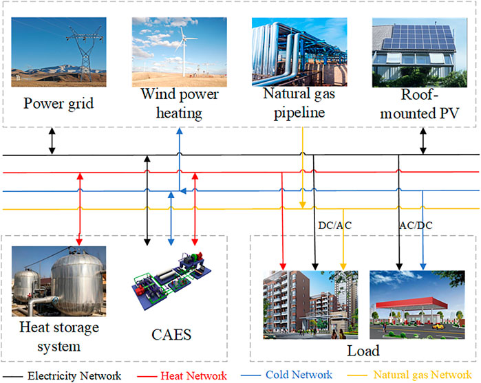
Micro energy network is composed of the distributed power generation system, energy storage system, load, intelligent control device, and power grid (Hwang et al., 2012). MEN can operate independently or be coupled in a public network. For example, urban and rural residential areas, large office spaces, industrial and agricultural parks, and skyscrapers are all typical application scenarios of MEN. The Energy Efficiency Initiative aims to achieve the comprehensive optimization and scheduling of multiple energy sources through the conversion and storage of different energy carriers to save costs and reduce emissions.
The typical MEN composition is shown in Figure 1. Energy conversion and energy storage equipment are connected to each other through electricity, heat, cold and natural gas networks.
HA-CAES System Composition
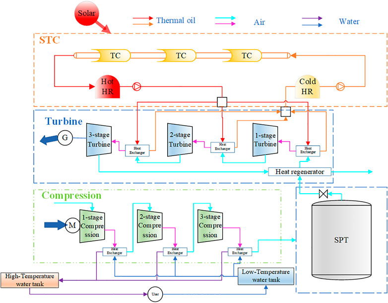
First of all, the distributed AA-CAES relies heavily on the compression heat recovered during charging process. However, the distributed CAES is seriously insufficient in compression heat. Fortunately, the high-altitude regions of the northwest have abundant solar energy resources. Therefore, we adopt the AA-CAES integrated with STC module that is defined as HA-CAES. And use it as the energy hub of ZEC-MEN. Secondly, it should be noted that the pressure ratio of each stage compressor is different. The number of compression stages is determined by the maximum pressure of the steel pipeline tank (SPT) and the type of compressor. The SPT in this paper can withstand a pressure of up to 10 MPa. Consequently, this article chooses a three-stage compressor to meet the requirements of design. The structure of the HA-CAES which has three-stage compression and three-stage expansion is shown in Figure 2. This system consists of four subsystems, including the compression subsystem, the STC subsystem, the turbine subsystem, and the air storage subsystem.
The compression subsystem includes a three-stage compressor and heat exchangers, a low-temperature water tank, and a high-temperature water tank. The STC subsystem includes a trough collector (TC), a cold heat reservoir (HR), and a hot HR. The cold HR and hot HR are called thermal energy storage system (TES). The turbine subsystem includes a three-stage turbine, a throttle valve, a heat regenerator, and three-stage heat exchangers as well. The air storage subsystem includes a SPT.
Compared with other energy storage technologies such as PHES and BES, HA-CAES is not only a zero-carbon-emission system and pollution-free energy storage method, but it also has the capability of multi-energy storage and supply. Therefore, HA-CAES can be used for cooling, heating, and power. While exerting the synergistic effect of multi-energy complementarity, it can enhance the flexibility of the power system and become an effective way to improve renewable energy accommodation.
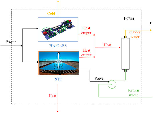
The design scheme of HA-CAES is shown in Figure 3. In addition, photovoltaic (PV) power and off-peak electricity are used as inputs to the HA-CAES hub. In addition, the HA-CAES hub can provide users with power during on-peak time.
Basic Assumptions
The modeling of HA-CAES satisfies the following assumptions.
1) The air is assumed to be an ideal gas.
2) The air storage tank adopts an isothermal constant volume model (Wang et al., 2016).
3) Compressor and turbine adopt an adiabatic model.
4) The heat storage tank adopts an adiabatic model.
5) Ignore the pressure loss of compressed air and water in the heat exchanger.
HA-CAES Modeling
Compressor
According to (Dielmann and van der Velden, 2003; Hwang et al., 2012; Mei et al., 2015; Chen et al., 2017), electricity consumption of
where
The electricity consumption of each stage of compressor should be kept within the lower and upper bound as follows:
where
The aggregate electricity demand of the compressor is given by:
where
The air mass flow rate of each stage compressor should be kept within the lower and upper bound as follows:
where
The relationship between air temperature of input and output of
where
Air pressure of each stage compressor is constrained as follows:
where
Turbine
For HA-CAES, electricity generated by
where
Electricity generated by each stage of the turbine should stay within these bounds:
where
Accordingly, we can get the aggregate electricity generation as follow:
where
The air mass flow rate of each stage turbine should be kept within this limit:
where
The connection between the input and output air temperature of the
where
Air pressure of each stage turbine is restricted as follows:
where
Air Storage Tank
The pressure of compressed air in the air storage tank at period
where
The air pressure in the air storage tank should be kept in the lower and upper bound:
where
Solar Thermal Collection Module
STC module converts solar energy into heat energy that can be directly used through devices such as mirrors, receivers, and heat exchangers:
where
Compressed Heat Recovery System
In the charging process, the compression heat generated by
where
Therefore, the aggregate thermal energy collected during charging process is the sum of that of each cooler,
Also, heat energy consumed by
where
Similarly, we can get the aggregate thermal energy consumed as follow
The state of charge (SOC) of the TES of HA-CAES can be depicted as
where
Operation of Green Pollution-Free Micro Energy Network
Objective Function
This article assumes that the HA-CAES hub, the heat collected by STC, and the heat pump are the thermal sources in the proposed ZCE-MEN, and the heat pump is the standby thermal source. At the same time, we think that the heat pump buys electricity from the grid. We aim to reduce MEN scheduling costs throughout the scheduling period:
where
The objective function 36) is subjected to the following constraints.
Constraints
Heat Pump and Circulating Water Pump
The aggregate thermal energy generated by the HA-CAES hub and heat pump equipped at node
where
The temperature of the water at each heat pump should be in the lower and upper bound as follow:
where
Electricity consumed by circulating water pump equipped at the node i is given by:
where
The power consumption of heat pump and circulating water should be in the lower and upper bound as follows:
where
Heat Load
Heat load at node
where
Each HA-CAES connected to the node
Therefore, the temperature of return water at heat load
where
District Heat Network
Since the liquid flows continuously (Budt et al., 2016; Liu et al., 2016), for each node
where
The relationship between the temperature of node
where
The relationship between node temperature and temperature of the pipe is depicted as:
where
Mass flow of each pipe
where
The pressure between input and output of pipe
where
During the circulation of water in the pipeline, the temperature drops exponentially.
where
Power Distribution Network
It is supposed that the DistFlow model is used to represent the PDN of proposed ZCE-MEN. The improved DistFlow model includes renewable energy, continuous and discrete reactive power compensators. Thus, the PDN of ZCE-MEN can be expressed as (Baran and Wu, 1989; Farivar and Low, 2013; Ji et al., 2013; Liu et al., 2015; Wang et al., 2015; Wei et al., 2017):
where
Eq. 54 and Eq. 55 depict the balance of the active power and reactive power of PDN, respectively. Eq. 56 describes the voltage drops along the distribution line
The active power distribution of line
Model Simplifications
The dispatch model proposed above is a large-scale MINLP problem, which is difficult to solve by various existing solvers. In this section, the various parts of the models are linearized to obtain a MILP problem that is easy to solve with CPLEX.
CP-CT Operation Model Simplification
Due to the complexity of hydrothermal dynamics, it is difficult to adjust air pressure
Big M Method Simplification
The following part takes the OLTC branch
where
Similarly, the other nonlinear constraint problems in PDN can be transformed into linearization problems by using the Big M method, which simplifies the solving process and will not be described here.
The original MINLP has been simplified and transformed into a MILP problem that can be solved efficiently with CPLEX.
Results and Discussion
System Settings
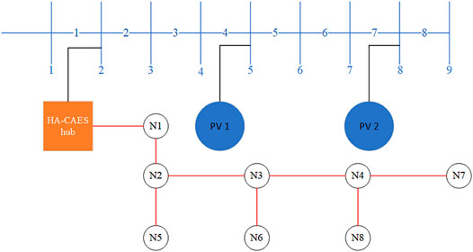
Figure 4 shows the configuration of ZCE-MEN. This ZCE-MEN consists of a 9-bus PDN, an eight- node DHN, a HA-CAES hub, a STC, and a heat pump. A HA-CAES hub coupled with STC is installed at bus 2. PV is installed at bus 4, 8, respectively. Equipped with a heat pump at node N1. Because the heat pump purchases electricity directly from the grid. Therefore, DHN and PDN can only be connected through a HA-CAES hub. The relevant parameters of the eight nodes DHN are shown in Appendix Table A1.
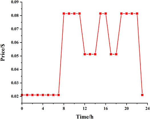
For the Chinese sustainable development policy, the location of this ZCE-MEN used to be an industrial area, which was relocated due to severe pollution and high energy consumption. Although it is now an agricultural park, the electricity price is still the same as the previous one. The time-of-use power price in the Qinghai power grid is shown in Figure 5. The data was from Qinghai Development and Reform Commission (Zhang, 2020).
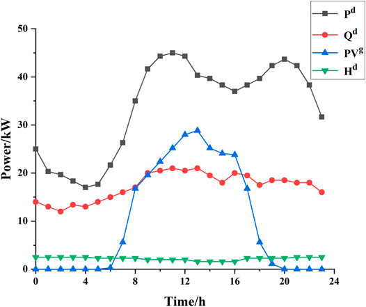
Figure 6 shows the demand of the ZCE-MEN for power and heat and the available solar power.
Simulation of HA-CAES
To verify the model, the modeling and operation are based on the 100kW HA-CAES system located in Qinghai University, Xining City, Qinghai Province (Chen et al., 2018). It is mainly assumed that air is an ideal gas, and the specific heat capacity of air, heat transfer medium, and heat storage medium is constant. Because northwest villages need more heat than electricity. This paper selects the Major Cold solar term (January 20, 2021) as a typical day. The solar irradiance data used is from the measured data in Huzhu County, Haidong City, Qinghai Province. The longitude is 101.956,734 and the latitude is 34.83994. The main parameters of the system are detailed in Table 1:
The simulation parameters of HA-CAES are mainly referred to (Jafarkazemi et al., 2016; Bai et al., 2020; Bai et al., 2021), and we have refined the parameters to be more reasonable according to the actual situation. Table 2 and Table 3 illustrate the rated parameters of the selected three-stage compressor and three-stage turbine.
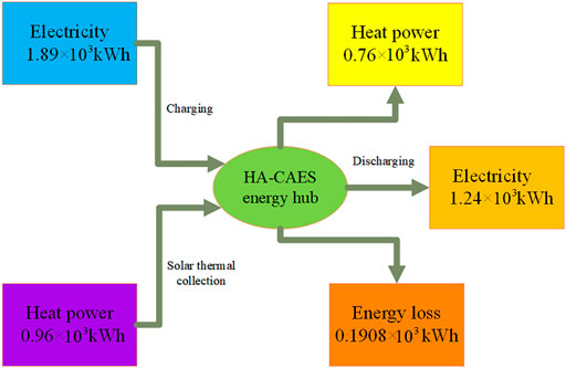
The energy flow in the whole process of the designed HA-CAES hub is illustrated in Figure 7. The E-E conversion efficiency is the ratio of the energy generated by the turbine to the energy consumed by compressor. The round trip efficiency refers to the ratio of the energy output to the input system in a cycle of energy storage-standstill-release energy (Mei et al., 2015). For the system proposed in this paper, the E-E energy conversion efficiency
Simulation Result
Operation of HA-CAES
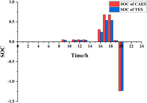
The SOC of HA-CAES and that of TES of the HA-CAES hub are indicated in Figure 8. From this figure, we can see that HA-CAES, during the period of low electricity price, for example, from t = 9, t = 11 to t = 13 and t = 17 to t = 18, uses free solar power and cheap electricity to fill air into the SPT to store energy in two forms, namely, the thermal energy and the molecular potential energy. In the case of consuming a certain amount of thermal energy in TES, the latter one can be used to drive the turbine to generate electricity at the on-peak time, for example, periods t = 20. At the same time, it can directly provide residents with heat to reduce consumption.
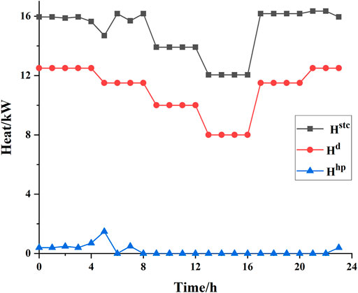
Figure 9 shows the heat power output of the STC module, HA-CAES hub, and the heat pump. Villages in the northwest rely almost as much on heat as electricity. Although part of the heat load of DHN is provided by the heat pump. Due to the coupling of the STC module, the heat generated by it can heat the compressed air, and can also be directly used to provide thermal for the residents. It can be illustrated from Figure 9 that the load of the heat pump has been greatly reduced. Most of the heat is provided by STC module. Consequently, the cost is greatly saved.
Operation Costs
Table 4 illustrates the operation costs under different operation modes. This table compares the operating costs of the ZCE-MEN and the separate operations of PDN and DHN. Through the joint optimization of the PDN and DHN for the HA-CAES hub, there has been a conspicuous reduction. The operating cost of the proposed ZCE-MEN is reduced by 4.78% compared with the single optimization of DHN and PDN. The comparison results show that the introduction of STC module enriches the heat source of the system. This enables the HA-CAES hub to provide more heat demand while ensuring the power supply load. It reduces the need for heat pumps to purchase electricity from the grid, thereby improving the operating economy of the system. And the level of solar output level has a great influence on the operation costs.
Solar Power Curtailment
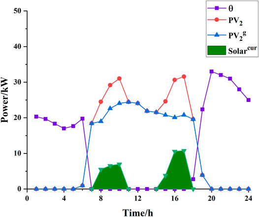
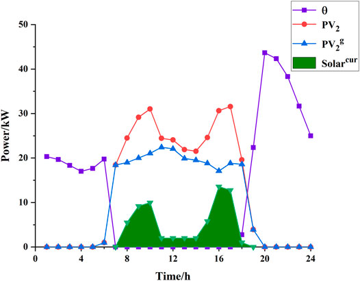
The electricity purchased from the power grid, PV power plants, and curtailment power of solar in different operation modes with and without HA-CAES are compared in Figure 10 and Figure 11.
We can compare Figure 10 and Figure 11 to know that by using the HA-CAES hub in the proposed ZCE-MEN to store the free solar energy during off-peak hours, and use the stored energy to provide power or heat demand during on-peak hours, such as t = 20 to t = 23. The green shades in Figure 10 and Figure 11 show that compared with traditional MEN, the solar curtailment rate of ZCE-MEN has been greatly reduced. Consequently, the need to purchase electricity from the grid can be reduced, thereby reducing system operating costs.
Optimal Temperature Distribution
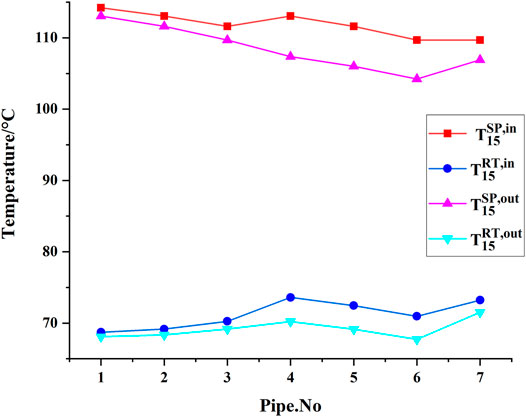
Figure 12 and Figure 13 present the optimal temperature distribution of HA-CAES at the on-peak heat load period and off-peak heat load period. Comparing these two figures, the temperatures of the supply system are much higher than the return system. Meanwhile, the temperatures of the return system at the off-peak time are much lower than the on-peak time, so it can be seen that the recycling water system is responsible for a large part of the heating demand. It provides effective protection for residents’ domestic water.
The Effect of Irradiance on the Overall Performance
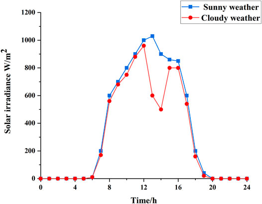
The STC heats the heat-conducting oil in the hot HR to 300°C by focusing and collecting heat, and then exchanges heat with the air through the heat exchange system to heat the compressed air. The heat-conducting oil after heat exchange enters the cold HR and is used to supply heat to residents. After that, it is transported to the STC to be heated again. Figure 14 shows the measured solar irradiation intensity on sunny and cloudy days. On a typical sunny day, the design temperature can usually be reached within one cycle. However, due to insufficient solar on typical cloudy days, it is difficult for the heat-conducting oil in the hot HR to reach the design temperature after one cycle. At this point, it will continue to circulate heating. From Figure 14, we can see that the solar irradiation intensity is about 70% of that on sunny days.
The heating is designed according to the requirements of national standards. The heating temperature of the room was kept between 16 C and 24°C, the qualified heating temperature was above 16°C, and the standard room temperature was above 18 C (Health Legal System and S, 2003; Ministry of HousingUrban-, 2012). Table 5 shows the rated heating parameters of the ZCE-MEN.
Table 6 demonstrates the situation of power supply and heating on different typical days. To analyze the impact of solar irradiance on the system more clearly, only HA-CAES is considered. No heat pump is used for heating. It can be seen from the figure that under the premise of ensuring stable electricity consumption for residents, the heating area on sunny days is 34% larger than that on cloudy days. Under the premise of ensuring stable heating for residents, the power supply time on a sunny day is 43% longer than in the cloudy scenario. This has largely solved the problem of heating difficulties in northwestern villages. The use of HA-CAES as a clean energy hub has solved environmental pollution. Thereby effectively protecting the fragile ecological environment of the Qinghai-Tibet Plateau.
Although cloudy weather has a greater impact on the system, the Qinghai-Tibet Plateau has abundant solar energy resources. The annual heating season is not the rainy season. Therefore, there is less cloudy weather, and most of the time the solar irradiance is at a satisfactory level. Therefore, HA-CAES is still very helpful to satisfy residents’ electricity and heat demands.
Conclusion
In this paper, a ZCE-MEN using HA-CAES with STC as an energy hub is proposed and analyzed. HA-CAES uses the compression heat and the solar thermal energy collected by STC to heat the compressed air during the discharging process to enhance the system efficiency. In addition, the excess heat energy can also provide heating for residents to reduce operating costs. A mathematical model including energy and cost analysis was developed. Through simulation verification, HA-CAES still has high efficiency in the regions of low air pressure and low air mass flow rate on the plateau. The E-E energy conversion and round trip efficiency can reach 65.61 and 70.18%. The introduction of STC significantly improves the system efficiency by increasing the turbine input temperature. Compared with the independent MEN system, the proposed ZCE-MEN with HA-CAES has economic benefits. The average daily operating cost of the entire system has been reduced by 4.78%. Furthermore, the proposed system also improves solar power curtailment. Although the solar irradiance will affect the efficiency of the system. Due to the abundant solar resource in the northwestern villages, there is less cloudy weather. Therefore, the system can still protect residents’ electricity and heat to a large extent. Therefore, HA-CAES can become an energy hub of villages and cities. It is of great significance to promote the deep decarbonization of the energy system.
Please note that the system parameters in this article are assumed to be definite, and uncertainty is not considered. And solar power is the daily average. Therefore, this method cannot adapt to the uncertain situation in the actual system. Our further work will optimize the regulation of uncertain MEN, and use robust optimization methods to deal with such problems. In addition, due to the large temperature changes in the northwest villages, parameters such as the specific heat capacity will affect the system. We also focus on the study of these thermal parameters on the overall performance of the system in future research.
Data Availability Statement
The raw data supporting the conclusions of this article will be made available by the authors, without undue reservation.
Author Contributions
QJ: conceptualization, writing-original draft preparation, software. TL: practical engineering guidance, project administration, interpretation of data for the work. XC: funding acquisition, writing review and editing, supervision. LC: validation, methodology. YS: validation. SM: supervision. All authors have read and agreed to the published version of the manuscript.
Funding
This study was supported by Qinghai Province Key Laboratory of Photovoltaic grid connected power generation technology (Grant No. 106000004816) and the Scientific and Technological Project of Qinghai Province (Grant No. 2018-GX-A6).
Conflict of Interest
Author TL was employed by Economics and Technological Research Institute of State Grid Qinghai Electric Power Company and Clean Energy Development Research Institute of State Grid Qinghai Electric Power Company.
The remaining authors declare that the research was conducted in the absence of any commercial or financial relationships that could be construed as a potential conflict of interest.
Publisher’s Note
All claims expressed in this article are solely those of the authors and do not necessarily represent those of their affiliated organizations, or those of the publisher, the editors and the reviewers. Any product that may be evaluated in this article, or claim that may be made by its manufacturer, is not guaranteed or endorsed by the publisher.
Abbreviations
ZCE-MEN, Zero-carbon micro-energy network; AA-CAES, Advanced adiabatic compressed air energy storage; STC, Solar thermal collector; HA-CAES, Hybrid adiabatic compressed air energy storage; PDN, Power distribution network; DHN, District heating network; MINLP, Mixed-integer nonlinear programming; MILP, Mixed-integer linear programming problem; E-E, Electric to electric; MEN, Micro energy network; BES, Battery energy storage; PHES, Pumped hydro energy storage; CAES, Compressed air energy storage; SPT, Steel pipeline tank; TC, Trough collector; HR, Heat reservoir; TES, Thermal energy storage; PV, Photovoltaic; SOC, State of charge; OLTC, On load tap changer, CP-CT; Constant pressure and constant temperature.
Appendix A1
References
Alirahmi, S. M., Bashiri Mousavi, S., Razmi, A. R., and Ahmadi, P. (2021). A Comprehensive Techno-Economic Analysis and Multi-Criteria Optimization of a Compressed Air Energy Storage (CAES) Hybridized with Solar and Desalination Units. Energ. Convers. Management 236, 114053. doi:10.1016/j.enconman.2021.114053
Alirahmi, S. M., Razmi, A. R., and Arabkoohsar, A. (2021). Comprehensive Assessment and Multi-Objective Optimization of a green Concept Based on a Combination of Hydrogen and Compressed Air Energy Storage (CAES) Systems. Renew. Sustainable Energ. Rev. 142, 110850. doi:10.1016/j.rser.2021.110850
Arabkoohsar, A., Dremark-Larsen, M., Lorentzen, R., and Andresen, G. B. (2017). Subcooled Compressed Air Energy Storage System for Coproduction of Heat, Cooling and Electricity. Appl. Energ. 205, 602–614. doi:10.1016/j.apenergy.2017.08.006
Bai, J., Liu, F., Xue, X., Wei, W., Chen, L., Wang, G., et al. (2021). Modelling and Control of Advanced Adiabatic Compressed Air Energy Storage under Power Tracking Mode Considering Off-Design Generating Conditions. Energy 218, 119525. doi:10.1016/j.energy.2020.119525
Bai, J., Wei, W., Chen, L., and Mei, S. (2020). Modeling and Dispatch of Advanced Adiabatic Compressed Air Energy Storage under Wide Operating Range in Distribution Systems with Renewable Generation. Energy 206, 118051. doi:10.1016/j.energy.2020.118051
Baran, M. E., and Wu, F. F. (1989). Network Reconfiguration in Distribution Systems for Loss Reduction and Load Balancing. IEEE Power Eng. Rev. 9 (4), 101–102. doi:10.1109/mper.1989.4310642
Bitaraf, H., and Rahman, S. (2018). Reducing Curtailed Wind Energy through Energy Storage and Demand Response. IEEE Trans. Sustain. Energ. 9 (1), 228–236. doi:10.1109/TSTE.2017.2724546
Budt, M., Wolf, D., Span, R., and Yan, J. (2016). A Review on Compressed Air Energy Storage: Basic Principles, Past Milestones and Recent Developments. Appl. Energ. 170, 250–268. doi:10.1016/j.apenergy.2016.02.108
Chen, J., Liu, W., Jiang, D., Zhang, J., Ren, S., Li, L., et al. (2017). Preliminary Investigation on the Feasibility of a Clean CAES System Coupled with Wind and Solar Energy in China. Energy 127, 462–478. doi:10.1016/j.energy.2017.03.088
Chen, X., Zhang, T., Xue, X., Chen, L., Li, Q., and Mei, S. (2018). A Solar-Thermal-Assisted Adiabatic Compressed Air Energy Storage System and its Efficiency Analysis. Appl. Sci. 8 (8), 1390. doi:10.3390/app8081390
Cheng, C., Blakers, A., Stocks, M., and Lu, B. (2019). Pumped Hydro Energy Storage and 100% Renewable Electricity for East Asia. Glob. Energ. Interconnection 2 (5), 386–392. doi:10.1016/j.gloei.2019.11.013
Dielmann, K., and van der Velden, A. (2003). “Virtual Power Plants (VPP) - a New Perspective for Energy Generation? Proceedings of the 9th International Scientific and Practical Conference of Students, Post-graduates Modern Techniques and Technologies, Tomsk, Russia, 7-11 April 2003 (Piscataway, New Jersey, United States: IEEE), 18–20. doi:10.1109/SPCMTT.2003.1438108
Ding, T., Liu, S., Yuan, W., Bie, Z., and Zeng, B. (2016). A Two-Stage Robust Reactive Power Optimization Considering Uncertain Wind Power Integration in Active Distribution Networks. IEEE Trans. Sustain. Energ. 7 (1), 301–311. doi:10.1109/TSTE.2015.2494587
Farivar, M., and Low, S. H. (2013). Branch Flow Model: Relaxations and Convexification-Part I. IEEE Trans. Power Syst. 28 (3), 2554–2564. doi:10.1109/TPWRS.2013.2255317
Fly, A., Kirkpatrick, I., and Chen, R. (2021). Low Temperature Performance Evaluation of Electrochemical Energy Storage Technologies. Appl. Therm. Eng. 189, 116750. doi:10.1016/j.applthermaleng.2021.116750
Health Legal System and Supervision Bureau of the Ministry of Health (2003). Indoor Air Quality Standard" Implementation Guide. Beijing: China Standard Press.
Hwang, T., Choi, M., Kang, S., and Lee, I. (2012). “Design of Application-Level Reference Models for Micro Energy Grid in IT Perspective,” in Proceedings of the 2012 8th International Conference on Computing and Networking Technology (INC, ICCIS and ICMIC), Gyeongju, Korea, 27-29 Aug. 2012 (Piscataway, New Jersey, United States: IEEE), 180–183.
Jafarkazemi, F., Ahmadifard, E., and Abdi, H. (2016). Energy and Exergy Efficiency of Heat Pipe Evacuated Tube Solar Collectors. Therm. Sci. 20 (1), 327–335. doi:10.2298/TSCI130227150J
Jakiel, C., Zunft, S., and Nowi, A. (2007). Adiabatic Compressed Air Energy Storage Plants for Efficient Peak Load Power Supply from Wind Energy: the European Project AA-CAES. Ijetp 5 (3), 296–306. doi:10.1504/IJETP.2007.014736
Ji, Z., Kang, C., Chen, Q., Xia, Q., Jiang, C., Chen, Z., et al. (2013). Low-carbon Power System Dispatch Incorporating Carbon Capture Power Plants. IEEE Trans. Power Syst. 28 (4), 4615–4623. doi:10.1109/TPWRS.2013.2274176
Jin, H., Hong, H., Wang, B., Han, W., and Lin, R. (2005). A New Principle of Synthetic cascade Utilization of Chemical Energy and Physical Energy. Sci. China Ser. E 48 (2), 163–179. doi:10.1360/04ye0234
Kim, Y. M., Shin, D. G., and Favrat, D. (2011). Operating Characteristics of Constant-Pressure Compressed Air Energy Storage (CAES) System Combined with Pumped Hydro Storage Based on Energy and Exergy Analysis. Energy 36 (10), 6220–6233. doi:10.1016/j.energy.2011.07.040
Liu, B., Liu, F., Mei, S., and Chen, Y. (2015). “AC-constrained Economic Dispatch in Radial Power Networks Considering Both Continuous and Discrete Controllable Devices,” in Proceedings of the The 27th Chinese Control and Decision Conference (2015 CCDC), Qingdao, China, 23-25 May 2015 (Piscataway, New Jersey, United States: IEEE), 6249–6254. doi:10.1109/CCDC.2015.7161937
Liu, X., Wu, J., Jenkins, N., and Bagdanavicius, A. (2016). Combined Analysis of Electricity and Heat Networks. Appl. Energ. 162, 1238–1250. doi:10.1016/j.apenergy.2015.01.102
Liu, Y.-h., Dong, G.-r., Li, S., and Dong, Y.-x. (2005). Status, Causes and Combating Suggestions of sandy Desertification in Qinghai-Tibet Plateau. Chin. Geograph.Sc. 15 (4), 289–296. doi:10.1007/s11769-005-0015-9
Llamas, B., Ortega, M. F., Barthelemy, G., de Godos, I., and Acién, F. G. (2020). Development of an Efficient and Sustainable Energy Storage System by Hybridization of Compressed Air and Biogas Technologies (BIO-CAES). Energ. Convers. Management 210, 112695. doi:10.1016/j.enconman.2020.112695
Luo, X., Wang, J., Dooner, M., and Clarke, J. (2015). Overview of Current Development in Electrical Energy Storage Technologies and the Application Potential in Power System Operation. Appl. Energ. 137, 511–536. doi:10.1016/j.apenergy.2014.09.081
Maddukuri, S., Malka, D., Chae, M. S., Elias, Y., Luski, S., and Aurbach, D. (2020). On the challenge of Large Energy Storage by Electrochemical Devices. Electrochimica Acta 354, 136771. doi:10.1016/j.electacta.2020.136771
Mei, S., Wang, J., Tian, F., Chen, L., Xue, X., Lu, Q., et al. (2015). Design and Engineering Implementation of Non-supplementary Fired Compressed Air Energy Storage System: TICC-500. Sci. China Technol. Sci. 58 (4), 600–611. doi:10.1007/s11431-015-5789-0
Ministry of HousingUrban-Rural Development (2012). Etc. GB50736-2012 "Code for Design of Heating, Ventilation and Air Conditioning of Civil Buildings. Beijing: China Construction Industry Press.
Rehman, S., Al-Hadhrami, L. M., and Alam, M. M. (2015). Pumped Hydro Energy Storage System: A Technological Review. Renew. Sustainable Energ. Rev. 44, 586–598. doi:10.1016/j.rser.2014.12.040
Roushenas, R., Razmi, A. R., Soltani, M., Torabi, M., Dusseault, M. B., and Nathwani, J. (2020). Thermo-environmental Analysis of a Novel Cogeneration System Based on Solid Oxide Fuel Cell (SOFC) and Compressed Air Energy Storage (CAES) Coupled with Turbocharger. Appl. Therm. Eng. 181, 115978. doi:10.1016/j.applthermaleng.2020.115978
Sadeghi, S., and Askari, I. B. (2019). Prefeasibility Techno-Economic Assessment of a Hybrid Power Plant with Photovoltaic, Fuel Cell and Compressed Air Energy Storage (CAES). Energy 168, 409–424. doi:10.1016/j.energy.2018.11.108
Salvini, C. (2017). Performance Assessment of a CAES System Integrated into a Gas-Steam Combined Plant. Energ. Proced. 136, 264–269. doi:10.1016/j.egypro.2017.10.280
Saputro, E. A., and Farid, M. M. (2018). A Novel Approach of Heat Recovery System in Compressed Air Energy Storage (CAES). Energ. Convers. Manag. 178, 217–225. doi:10.1016/j.enconman.2018.10.024
Semprini, S., Sánchez, D., and De Pascale, A. (2016). Performance Analysis of a Micro Gas Turbine and Solar Dish Integrated System under Different Solar-Only and Hybrid Operating Conditions. Solar Energy 132, 279–293. doi:10.1016/j.solener.2016.03.012
Sun, J., Wang, Z., and Li, G. (2018). Measuring Emission-Reduction and Energy-Conservation Efficiency of Chinese Cities Considering Management and Technology Heterogeneity. J. Clean. Prod. 175, 561–571. doi:10.1016/j.jclepro.2017.12.042
Wang, J., Lu, K., Ma, L., Wang, J., Dooner, M., Miao, S., et al. (2017). Overview of Compressed Air Energy Storage and Technology Development. Energies 10 (7), 991. doi:10.3390/en10070991
Wang, S., Zhang, X., Yang, L., Zhou, Y., and Wang, J. (2016). Experimental Study of Compressed Air Energy Storage System with thermal Energy Storage. Energy 103, 182–191. doi:10.1016/j.energy.2016.02.125
Wang, Z., Chen, B., Wang, J., Begovic, M. M., and Chen, C. (2015). Coordinated Energy Management of Networked Microgrids in Distribution Systems. IEEE Trans. Smart Grid 6 (1), 45–53. doi:10.1109/TSG.2014.2329846
Wei, W., Mei, S., Wu, L., Wang, J., and Fang, Y. (2017). Robust Operation of Distribution Networks Coupled with Urban Transportation Infrastructures. IEEE Trans. Power Syst. 32 (3), 2118–2130. doi:10.1109/TPWRS.2016.2595523
Xiao, J., Li, G., Xie, L., Wang, S., and Yu, L. (2021). Decarbonizing China's Power Sector by 2030 with Consideration of Technological Progress and Cross-Regional Power Transmission. Energy Policy 150, 112150. doi:10.1016/j.apenergy.2019.01.15410.1016/j.enpol.2021.112150
Xue, X. D., Mei, S. W., Lin, Q. Y., Chen, L., and Chen, Y. (2016). Energy Internet Oriented Non-supplementary Fired Compressed Air Energy Storage and Prospective of Application. Power Syst. Technol. 40 (1), 164–171. doi:10.13335/j.1000-3673.pst.2016.01.022
Yang, Y., Bremner, S., Menictas, C., and Kay, M. (2018). Battery Energy Storage System Size Determination in Renewable Energy Systems: A Review. Renew. Sustainable Energ. Rev. 91, 109–125. doi:10.1016/j.rser.2018.03.047
Yuan, X., Cheng, S., and Wen, J. (2013). Prospects Analysis of Energy Storage Application in Grid Integration of Large-Scale Wind Power. Dianli Xitong Zidonghua(Automation Electric Power Systems) 37 (1), 14–18. doi:10.7500/AEPS201210050
Zhang, D. (2020). Qinghai Development and Reform Commission. Available at: http://fgw.qinghai.gov.cn/zfxxgk/sdzdgknr/fgwwj/202012/t20201218_76157.html (Accessed December 18, 2020).
Keywords: zero carbon emission micro-energy network, hybrid compressed air energy storage system, solar thermal collection module, power distribution network, district heating network, mixed integer linear programming
Citation: Jia Q, Liu T, Chen X, Chen L, Si Y and Mei S (2021) Optimized Regulation of Hybrid Adiabatic Compressed Air Energy Storage System for Zero-Carbon-Emission Micro-Energy Network. Front. Energy Res. 9:745457. doi: 10.3389/fenrg.2021.745457
Received: 22 July 2021; Accepted: 16 November 2021;
Published: 09 December 2021.
Edited by:
Aldo Bischi, Skolkovo Institute of Science and Technology, RussiaReviewed by:
Yusuf Bicer, Hamad bin Khalifa University, QatarWei He, University of Warwick, United Kingdom
Copyright © 2021 Jia, Liu, Chen, Chen, Si and Mei. This is an open-access article distributed under the terms of the Creative Commons Attribution License (CC BY). The use, distribution or reproduction in other forums is permitted, provided the original author(s) and the copyright owner(s) are credited and that the original publication in this journal is cited, in accordance with accepted academic practice. No use, distribution or reproduction is permitted which does not comply with these terms.
*Correspondence: Xiaotao Chen, Y2hlbnhpYW9fcWh1QGZveG1haWwuY29t
 Qiwei Jia
 Tingxiang Liu2,3
 Yang Si
 Shengwei Mei