 Xueyong Qu1
 Hongzhong Xu
 Shuqin Fan
94% of researchers rate our articles as excellent or good
Learn more about the work of our research integrity team to safeguard the quality of each article we publish.
Find out more
ORIGINAL RESEARCH article
Front. Energy Res., 06 January 2022
Sec. Wind Energy
Volume 9 - 2021 | https://doi.org/10.3389/fenrg.2021.741703
This article is part of the Research TopicAerodynamic Upgrades of Wind Turbines and Wind FarmsView all 5 articles
In order to improve the unit-power of a wind-driven generator, a wind concentrator with complex shape is installed in front of the impeller, which makes the airflow integrated and accelerated. It is important to manufacture the wind concentrator with high precision. The double-roller clamping spinning (DRCS) is a dieless, flexible spinning process that is very suitable for forming a wind concentrator with complex shape. The profile of a wind concentrator is divided into two parts: the contraction section and the expanding section. The process routes of both the contraction section and the expanding section are determined, and roller path equations are derived. Then the finite element (FE) analysis model that can describe the plastic deformation behavior of the DRCS forming for a wind concentrator is established, and the DRCS process of the flange is simulated. Furthermore, the wall-thickness distribution on the expanding section during the forming process is obtained. Finally, the reliability of the FE model is verified using the experimental results.
To relieve the energy crisis, more and more new energy sources have been developed, such as wind energy, solar energy, hydrogen energy, and so on. Wind energy is a kind of renewable and clean energy and has been widely used in wind power generation. For the development of wind power equipment, it is important to improve the efficiency of wind power units, and meanwhile ensure the safety of use and proper manufacturing cost. To improve the unit power of the wind-driven generator, a wind concentrator with a complex shape is installed in front of the impeller, which makes the airflow integrated and accelerated. Thus, it is important to design and manufacture the wind concentrator with a satisfactory shape and high precision. Generally, the wind concentrator is formed by three methods, which are deep drawing forming combined tailor-welding process, integral die forming process, and composite forming process of shear spinning and deep drawing spinning. The first method has a high cost of the mold. Moreover, the surface quality and aerodynamic characteristics are limited by the quality and the quantity of the welded seam. The second method is a kind of integral forming process, which needs more energy and much expensive equipment. Also, it cannot ensure the local forming quality. The third method adopts shear spinning. In the shear spinning process, the different sizes of parts need different molds, which results in the high cost of the mold.
A new double-roller clamping spinning (DRCS) process is suitable for forming the wind concentrator with a complex profile. Figure 1 shows a schematic of the DRCS process. Before the DRCS process, a thin-walled cylindrical workpiece is fixed on the internal expanding clamp, which expands radially under an axial compressive load to tightly clamp the cylindrical workpiece. At the same time, two rollers clamp the section, which is to be formed and exert forming the load. In the DRCS spinning process, the workpiece rotates together with the clamp, while the two rollers rotate on their axis, performing three degrees of freedom motion driven by the spinning head (linear motion along the Z and X axes, and rotation around the Y axis). Thus the thin-walled cylindrical part with a complex profile can be formed.
FIGURE 1. Schematic illustration of the DRCS process.
In addition, the DRCS process can be used to form other key parts with hollow axisymmetric shape, such as fans and ventilators of heating, ventilating, and air conditioning (HVAC), and hydrogen storage of fuel cells for electric vehicles that is the research focus in recent years (Ding et al., 2020a; Ding et al., 2020b).
Many scholars have investigated conventional spinning, flow forming, and shear spinning (Wang and Long, 2011; Childerhouse and Long, 2019; Wang et al., 2020; Huang et al., 2021). However very few researchers studied the DRCS process. Fan, et al. used two methods to establish the FE model of DRCS for a cylinder with a rectangular flange. The first method is the same as that for actual working conditions, where the workpiece rotates around its axis. The second method makes the workpiece motionless, unlike in the actual forming process. Different methods may be chosen according to the different computing conditions (Fan et al., 2010). To save computing time, the authors used the second method to establish an FE model of the DRCS and solved key problems in establishing the model. Then, a precise three-dimensional elastoplastic FE model was established for DRCS, and the FE model was verified by experiments (Fan et al., 2011). Moreover, the authors carried out experimental research and many FE simulations and obtained the effects of the main process parameters, such as the roller radius, the spacing between two rollers, and the feed rate of rollers on the DRCS process (Fan et al., 2012). Both a finite element numerical simulation and experimental research on the DRCS process were carried out. DRCS spinning force, stress, strain, and wall thickness distributions for the different deformation areas were obtained. Furthermore, microstructure analysis and tensile test results show that the flanged thin-walled cylinder formed by DRCS has good mechanical properties (Fan et al., 2018). The finite element model of the multi-pass DRCS for the sheet metal is established. The simulations on the multi-pass DRCS of the ordinary Q235A steel cylindrical part with the arc-shaped surface flange are carried out. The variations of the spinning forces and the distributions of the stresses, strains, and wall thickness during the multi-pass DRCS process are revealed (Fan et al., 2013).
All of the above research is valuable for the forming of wind concentrators. However, the wind concentrator used in the wind-driven generator is a kind of thin-walled cylinder part with a complex profile. The profile of the wind concentrator includes two parts: the contraction section and the expanding section, which are more than simple right-angle flange or bell mouthparts. Therefore, the roller path of DRCS for wind concentrators is more complex. To reveal the deformation mechanism of DRCS for the wind concentrator with a complex profile, FE simulations and experiments of the DRCS process for 6061-T6 aluminum alloy wind concentrator have been carried out in this study. First, the process route of DRCS for the wind concentrator is determined, and the roll path equations are deduced. Then the finite element model of DRCS for wind concentrators is established. The DRCS process of the wind concentrator is simulated, and the experiment results verified the reliability of the FE model.
Figure 2 shows the geometrical model of the wind concentrator, which consists of the diffusion ventilation section and the vortex forming section, and the vortex forming section is formed by a straight edge flange. The profile of the diffusion ventilation section is a cycloidal curve that includes the contraction section and the expanding section.
FIGURE 2. Geometry model of a wind concentrator.
It has been verified that the cycloidal curve in the diffusion ventilation section has higher output power and output efficiency than the straight one. Increasing the curvature of the curve causes the increase of air outlet area of the diffusion ventilation section, which can improve the output power. Table 1 shows the key geometric parameters of the wind concentrator.
TABLE 1. The key geometric parameters.
Both the contraction section and expanding section of the diffusion ventilation section in the wind concentrator can be formed by the DRCS process. During both forming processes, several AC servo motors are used to control the path of the roller.
First, the contraction section of the wind concentrator is formed, as shown in Figure 3A. In the forming process, a workpiece tube is fixed on the internal expanding clamp and rotates together with the clamp. Two rollers clamp the workpiece and exert the forming load, and the rollers perform motion according to the designed roller path. Second, the end region is flanged inward, which is convenient for clamping in the DRCS process of the expanding section.
FIGURE 3. (A) DRCS process for the contraction segment of a wind concentrator. (B) DRCS process of the expanding segment and vortex forming section of a wind concentrator.
After the contraction section is formed, the workpiece is removed. The blank of the second process is obtained through the first process. The straight side of the contraction section is fixed on the internal expanding clamp. Then the expanding section and the straight edge flange of the vortex forming section are formed successively by controlling the motion of rollers according to the designed roller path, as shown in Figure 3B. Finally, remove the straight side used for clamping, and the wind concentrator with a complex profile is obtained.
In order to perform satisfied roller motion in the DRCS process of wind concentrators, it is important to design the proper roller path. Furthermore, the roller path has an important influence on the forming quality and processing efficiency. Two cylindrical rollers are used in the single-pass DRCS process, which causes the line contact between the roller and the sheet metal. Thus, the loading action area is larger than that of the conventional spinning, and the plastic deformation of each pass spinning is larger. So spinning efficiency is higher.
The geometry model of the wind concentrator is shown in Figure 4. Figure 4A is the initial workpiece, Figure 4B is the contraction section after DRCS. Figure 4C is the expanding section after DRCS. The geometric parameters are shown in Table 2.
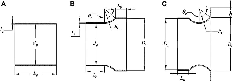
FIGURE 4. (A) Geometry model of the blank of a wind concentrator. (B) Contraction segment after DRCS. (C) Expanding segment after DRCS.
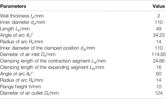
TABLE 2. Geometric parameters of the contraction segment.
It is shown in Figure 5A that the generatrix of deformation zone in the contraction section consists of a circular segment OM and line segment MN. Point Cs (0, Rsm) is the center of the circular segment. The equation of the circular segment OM is
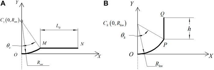
FIGURE 5. (A) The generatrix of deformation zone in a contraction segment. (B) The generatrix of deformation zone in an expanding segment.
where: Rsm -- Radius of the circular segment OM, and Rsm = Rs + tp/2.
θs -- Arc angular of the circular segment OM.
The equation of the line segment MN is
where: Lkj -- Length of the line segment MN.
It is shown in Figure 5B that the generatrix of the deformation zone in the expanding section consists of a circular segment OP and a line segment PQ. Point Ck (0, Rkm) is the center of the circular segment. The equation of the circular segment OP is
where: Rkm -- Radius of the circular segment OP, and Rkm = Rk + tp/2
θk -- Arc angular of the circular segment PQ.
The equation of the line segment PQ is
where: h -- Length of line segment PQ.
The DRCS process of a wind concentrator is simulated using the non-linear FE analysis software Abaqus/Explicit. Some simplification and reasonable assumptions of the DRCS are made for convenience. For example, the blank material is homogeneous, isotropic, and incompressible, the rollers and internal expanding clamp are rigid bodies, and no deformation occurs. Furthermore, the temperature effect is neglected.
6061-T6 aluminum alloy is chosen as the material of the wind concentrator in the simulation of the DRCS process, and the material parameters are determined using a tensile test. The main material parameters of 6061-T6 aluminum alloy are shown in Table 3, and its true stress-strain curve is shown in Figure 6. The cylindrical rollers are used in the DRCS process of wind concentrators. The diameter of the cylindrical roller is 20 mm, its length is 25 mm, and its round radius is 1 mm.

TABLE 3. Material parameters.
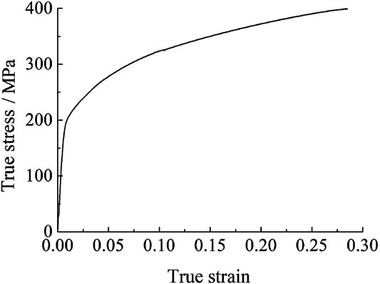
FIGURE 6. True stress-strain curve for 6061-T6 aluminum alloy.
First, the geometry model of DRCS for the contraction section of the wind concentrator is established. The parts include a workpiece tube of the contraction section, inner roller, outer roller, and internal expanding clamp. The workpiece tube is defined as a deformable shell, meshed by the S4R element, which is a four-node doubly curved general-purpose shell, reduced integration with hourglass control. To improve the analysis accuracy and efficiency, the deformation area of the workpiece has a higher density than the rest of the workpiece, and the mesh size of the deformation area is 0.83 mm, and that of the clamping area is 1.67 mm. Both the two rollers and the clamp are defined as analytical rigid bodies which is unnecessary to be meshed. Then the reference points of the rollers and the clamp are assigned to represent their motion in all degrees of freedom.
During the DRCS process, the workpiece-internal expanding clamp contact and workpiece-rollers contact are complex and dynamic. In this study, the contact pair is defined between the outer surface of the clamp and the inner surface of the workpiece tube. In addition, the contact pairs are defined between the outer surface of the outer roller and the outer surface of the workpiece tube, as well as between the outer surface of the inner roller and the inner surface of workpiece tube. Furthermore, a frictionless contact is set between the clamp and the workpiece tube, and the contact pair is constrained by binding. The penalty-contact method is used to set the contact properties between the rollers and the workpiece tube, and the friction coefficient is 0.2.
Next, the displacement and rotational freedom of the rigid bodies are defined in the boundary condition manager. The motion amplitude curve of the clamp is defined in the form of a smooth analysis step. Because the contact pair between the clamp and the workpiece tube is constrained by binding, the workpiece rotates with the clamp. The motion amplitude curve of the rollers is defined according to the equation of the roller path.
The main parameters in the simulation of the DRCS process are similar to the experimental conditions. The rotation rate of the workpiece is 180 r·min-1. Both the DRCS process of the contraction section and that of the expanding section have two forming stages: the stage of expanding forming and the stage of flanging forming. At the stage of expanding forming, the roller feed rate f is defined as the displacement of the rollers along the roller path when the workpiece rotates through a complete cycle around the main spindle. At the stage of flanging forming, the roller flanging feed rate f is defined as the rotating angle of the rollers when the workpiece rotates through a complete cycle around the main spindle. The roller feed rate is 0.5 mm·r-1, and the flanging feed rate is 0.05 rad·r-1 in the simulation.
An FE model for the DRCS process of the expanding section is established in the same way. The FE model of the DRCS process for wind concentrator is established, as shown in Figure 7. Figure 7A shows the FE model of DRCS for the contraction section, and Figure 7B shows that for the expanding section.
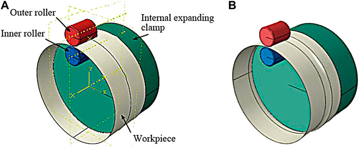
FIGURE 7. (A) Finite element model of a DRCS process for the contraction segment of a wind concentrator. (B) Finite element model of the DRCS process for the expanding segment of a wind concentrator.
Using the FE model, the simulation of DRCS for a wind concentrator is carried out. Figure 8A shows the wall thickness distribution on the contraction section of the wind concentrator at the two forming stages: the stage of expanding forming and the stage of flanging forming. The wall thickness distribution in the circumferential direction of the workpiece is uniform at the stage of expanding forming. It can be seen that material accumulation occurs in the arc transition area, where the wall thickness is higher than the initial one. The wall thickness gradually decreases from the arc transition area to the outer edge along the generatrix.
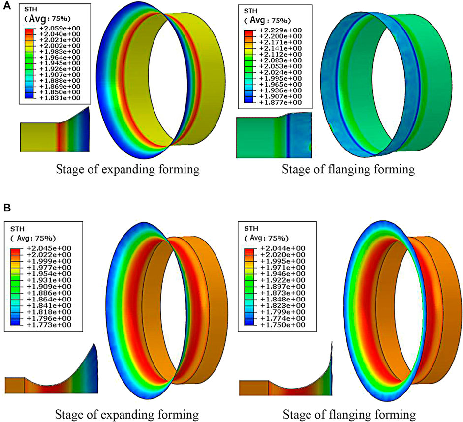
FIGURE 8. (A) Wall thickness distribution on the contraction segment of a wind concentrator. (B) Wall thickness distribution on the expanding segment of a wind concentrator.
The workpiece has a tendency of wrinkling and instability at the stage of flanging forming, which is restrained by the combined action of the two cylindrical rollers. Even so, the forming process is still affected, and there are fluctuations in the wall thickness distribution in the circumferential direction of the workpiece. Moreover, it can be seen that the wall thickness on the arc transition area is still higher than the initial one, which is similar to the stage of expanding forming. It is different than the wall thickness on the line segment which is thicker than that in the stage of expanding forming.
Figure 8B shows the wall thickness distribution on the expanding section of the wind concentrator at the two forming stages. The wall thickness distribution in the circumferential direction of the workpiece is uniform whichever the stage. It can be seen that material accumulation occurs in the arc transition area, where the wall thickness is higher than the initial one. The wall thickness gradually decreases from the arc transition area to the outer edge along the generatrix.
In order to verify the FE model of the DRCS process, experiments are carried out in this work. Figure 9A shows the experimental set-up. It can be seen the set-up mainly consists of an internal expanding clamp, AC servo motor of the clamp, a spinning head, and AC servo motors of the X-axis, Y-axis, and Z-axis. Based on the equations of the circular segment OP and PQ, the motion equations of the rollers are derived according to the motion relation of each axis of the experiment set-up. The partial derivation can be seen in the reference (Fan et al., 2019). The motion curves of rollers when forming the contraction section can be obtained, as shown in Figure 9B. Moreover, the motion curves of rollers when forming the expanding section can be obtained, as shown in Figure 9C. By controlling the speed and displacement of the AC servo motor in three directions, the rollers perform three degrees of freedom motion according to the designed curve equation.
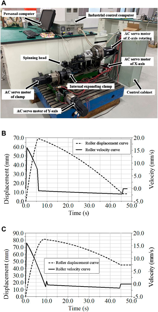
FIGURE 9. Experimental set-up and motion curves of the rollers. (A) Experimental set-up. (B) When forming the contraction section. (C) Motion curves of the rollers when forming the expanding segment.
The workpiece tubes are used in the experiment. The material of workpiece is 6060-T6 aluminum alloy, the inner diameter is 110 mm, the wall thickness is 2 mm, and the length is 50 mm.
Several duplicate experiments for the contraction section of the wind concentrator are carried out. Split the samples vertically to obtain the vertical sections and take 10 points uniformly in the deformation area of the sample. The wall thickness distributions of the deformation areas of the samples are obtained by measuring the thickness of the vertical sections, and then the average values of data on the thickness distributions in three groups are chosen as the final experiment data. In addition, then the final experiment data are compared with the simulation results.
The experiment process of DRCS for the contraction section of the wind concentrator is shown in Figure 10A. The workpiece of the contraction section after forming is shown in Figure 10B. Split the sample vertically to obtain a vertical section, as shown in Figure 10C, and take 10 points uniformly in the deformation area of the sample, as shown in Figure 10D.
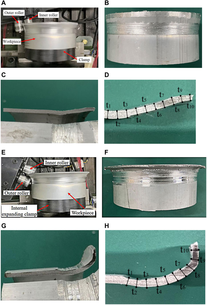
FIGURE 10. (A) Experiment process of DRCS for the expanding section of a wind concentrator. (B) Final formed sample. (C) Section of the sample. (D) Schematic diagram of monitor points for the wall thickness on the sample. (E) Experiment process of DRCS for the expanding section of a wind concentrator. (F) Final formed sample. (G) Section of the sample. (H) Schematic diagram of monitor points for the wall thickness on the sample.
The experiment of DRCS for the expanding section of the wind concentrator is carried out, as shown in Figure 10E. The workpiece of the expanding section after forming is shown in Figure 10F. Split the sample vertically to obtain a vertical section, as shown in Figure 10G, and take 10 points uniformly in the deformation area of the sample, as shown in Figure 10H.
Figure 11 shows the comparison of simulation results with experimental results of the wall thickness distribution. Figure 11A shows the contraction section of the wind concentrator. It can be seen that the simulation results, to a large extent, agree with the experimental results, and the maximum relative error is 2.5%. Figure 11B shows the expanding section of the wind concentrator. It shows the same conclusion as the contraction section.
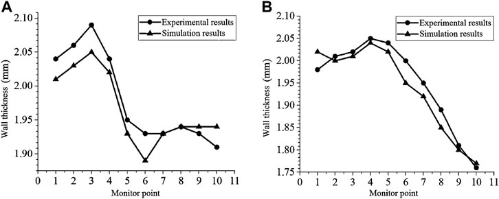
FIGURE 11. (A) Comparison curve of wall thickness on the contraction section. (B) Comparison curve of wall thickness on the expanding section.
The difference between experimental and simulation results is mainly due to the simplification of the model and the measurement error in the experiment. Thus, the FE model built in this study is reliable and practical, and the numerical simulation results are considered to be valid.
In this paper, the process route of DRCS for the wind concentrator was determined, and the roll path equations were deduced. Thus, the finite element analysis model of the DRCS for 6061-T6 aluminum alloy wind concentrator was established.
Furthermore, the DRCS process of the wind concentrator was simulated, and the wall-thickness distributions on the deformation area were obtained.
Then the experiment of DRCS for the expanding section of the wind concentrator was carried out, and the wall thickness distributions on the deformation area were measured and compared with the appropriate simulation results. It can be concluded that the FE model established in this study is reliable and practical.
The raw data supporting the conclusion of this article will be made available by the authors, without undue reservation.
Design the process route of the wind concentrator: X.Q. Design of the roller path: S.F., Y.H., and S.Z. Finite element simulation of the DRCS: H.X., S.F., and Y.H. Experiment: X.C. and Y.H. Wrote the paper: X.Q., H.X., S.F., and S.Z.
This research work was financially supported by the Fund of the State Key Laboratory of Metal Extrusion and Forging Equipment Technology (Nos. B1608101) and the National Natural Science Foundation of China (Nos. U1937203).
The authors declare that the research was conducted in the absence of any commercial or financial relationships that could be construed as a potential conflict of interest.
All claims expressed in this article are solely those of the authors and do not necessarily represent those of their affiliated organizations, or those of the publisher, the editors, and the reviewers. Any product that may be evaluated in this article, or claim that may be made by its manufacturer, is not guaranteed or endorsed by the publisher.
Childerhouse, T., and Long, H. (2019). Processing Maps for Wrinkle Free and Quality Enhanced Parts by Shear Spinning. Proced. Manufacturing 29, 137–144. doi:10.1016/j.promfg.2019.02.118
Ding, Z., Chen, Z., Ma, T., Lu, C.-T., Ma, W., and Shaw, L. (2020b). Predicting the Hydrogen Release Ability of LiBH4-Based Mixtures by Ensemble Machine Learning. Energ. Storage Mater. 27, 466–477. doi:10.1016/j.ensm.2019.12.010
Ding, Z., Li, H., and Shaw, L. (2020a). New Insights into the Solid-State Hydrogen Storage of Nanostructured LiBH4-MgH2 System. Chem. Eng. J. 385, 123856. doi:10.1016/j.cej.2019.123856
Fan, S., Yi, H., Gu, R., Zhao, S., Gao, J., and Du, W. (2019). Servo Motion Control System for Double-Roller Clamping Spinning Device. Forging Stamping Tech. 44 (12), 82–90.
Fan, S., Zhao, S., and Chen, C. (2018). Plastic Deformation Mechanism in Double-Roller Clamping Spinning of Flanged Thin-Walled Cylinder. Chin. J. Mech. Eng. 31 (3), 56. doi:10.1186/s10033-018-0254-1
Fan, S., Zhao, S., Zhang, Q., and Wang, C. (2010). Finite Element Model Determination of Double Rollers Clamping Expanding Spinning for Right-Angle Flange. J. Xi’an Jiaotong Univ. 44 (5), 66–70.
Fan, S. Q., Zhao, S. D., Zhang, Q., and Wang, C. H. (2011). Finite-element Modelling of a Novel Flanging Process on a cylinder with a Large Diameter-Thickness Ratio. Proc. Inst. Mech. Eng. B: J. Eng. Manufacture 225 (7), 1117–1127. doi:10.1177/2041297510393627
Fan, S., Zhao, S., and Zhang, Q. (2012). Research on Effects of Roller Parameters on Double Rollers Clamping Spinning. Jme 48 (18), 60–66. doi:10.3901/jme.2012.18.060
Fan, S., Zhao, S., Zhang, Q., and Li, Y. (2013). Plastic Mechanism of Multi-Pass Double-Roller Clamping Spinning for Arc-Shaped Surface Flange. Chin. J. Mech. Eng. 26 (6), 1127–1137. doi:10.3901/cjme.2013.06.1127
Huang, J., Jin, J., Deng, L., Wang, X., Gong, P., Zhang, M., et al. (2021). Theoretical Prediction of Flange Wrinkling in the First-Pass Conventional Spinning of Dual-Metal Sheets. J. Manufacturing Process. 62, 368–377. doi:10.1016/j.jmapro.2020.12.044
Wang, L., and Long, H. (2011). Investigation of Material Deformation in Multi-Pass Conventional Metal Spinning. Mater. Des. 32, 2891–2899. doi:10.1016/j.matdes.2010.12.021
Keywords: double-roller clamping spinning, wind concentrator, process route, roller path, FE model
Citation: Qu X, Xu H, Fan S, Cheng X, Zhao S and Hua Y (2022) Finite-Element Modelling of Double-Roller Clamping Spinning of Wind Concentrator. Front. Energy Res. 9:741703. doi: 10.3389/fenrg.2021.741703
Received: 15 July 2021; Accepted: 25 November 2021;
Published: 06 January 2022.
Edited by:
Unai Fernandez-Gamiz, University of the Basque Country, SpainReviewed by:
Rino Nelson, Indian Institute of Information Technology Design and Manufacturing Kancheepuram, IndiaCopyright © 2022 Qu, Xu, Fan, Cheng, Zhao and Hua. This is an open-access article distributed under the terms of the Creative Commons Attribution License (CC BY). The use, distribution or reproduction in other forums is permitted, provided the original author(s) and the copyright owner(s) are credited and that the original publication in this journal is cited, in accordance with accepted academic practice. No use, distribution or reproduction is permitted which does not comply with these terms.
*Correspondence: Shuqin Fan, c3VubnlmYW5AeGp0dS5lZHUuY24=
Disclaimer: All claims expressed in this article are solely those of the authors and do not necessarily represent those of their affiliated organizations, or those of the publisher, the editors and the reviewers. Any product that may be evaluated in this article or claim that may be made by its manufacturer is not guaranteed or endorsed by the publisher.
Research integrity at Frontiers
Learn more about the work of our research integrity team to safeguard the quality of each article we publish.