 Xiao-Hong Yuan1,2
 Chuang-Hui Qin
 Xun Liu
- 1Hubei Key Laboratory of Advanced Technology for Automotive Components, Wuhan University of Technology, Wuhan, China
- 2Hubei Collaborative Innovation Center for Automotive Components Technology, Wuhan University of Technology, Wuhan, China
In cold chain logistics, refrigerated trucks are used for long-distance transportation across cities, and insulated trucks are used for short-distance delivery within cities. However, the small insulated vans for short-distance transportation like delivering home in urban have heat leakage and no pre-cooling, the transportation time of traffic congestion becomes longer, resulting in poor insulation effect. So, to achieve stable temperature control is difficult, it leads to a big fluctuation in the temperature of the cargo. The thermoelectric cooling technology has the unique advantages of compact structure, flexible layout, no refrigerant, and environmental friendliness, which is very suitable for controlling the temperature of the small insulated vans. In the paper, relationship among COP, working power, and working current of the designed thermoelectric cooler (TEC) is investigated first. And then the best working state of the TEC is obtained. Next, set hot and cold dual temperature zones to ensure the effective use of energy based on thermoelectric cooling characteristics, arranged the cooling device in the insulated van, and revealed the changes in the temperature of the compartment and the cargo through the actual vehicle test. Compared the thermal insulation effect of the compartment with or without thermoelectric cooling technology through CFD. According to the simulation results, the cargo temperature of the insulated van fluctuates between 4 and 6°C within 2.5 h of actual delivery in urban, the insulated van using thermoelectric cooling technology can make the temperature of the cargo fluctuate within 1.5°C. The above proved the good insulated effect of the thermoelectric cooling insulated vans. Finally, the influence of the working time of the thermoelectric refrigeration system on the temperature control effect is also studied. The research results have a certain guiding significance for the application of thermoelectric cooling technology in insulated vans.
Introduction
With the construction of cold chain logistics, many e-commerce companies entered the market and began to deploy cold chain logistics construction.
In cold chain logistics, there are refrigerated trucks used for long-distance transportation across the city. Refrigerated vans refer to vehicles equipped with thermal insulated structures and refrigeration systems, and special vans used for refrigerated transportation. There is also short-distance home delivery insulated vans delivered to homes in cities. Generally, the insulated van is only equipped with insulated compartment, without refrigeration system. At present, refrigerated and insulated vehicles are the most important vehicles for road cold chain transportation (Zhao et al., 2018).
The increasing emphasis on environmental protection has promoted the rapid development of new energy vehicle technology, and the electrification of special operating vehicles and short-distance transportation vehicles is also imperative. Therefore, traditional refrigerated vehicles are also facing the transformation of driving energy (Liang et al., 2019). With the improvement of living standards and the acceleration of the pace of life, people’s demand for quick-frozen food and fresh food has increased significantly. In the entire cold chain of many quick-frozen foods, the urban “last one mile” delivery has become a weak logistics link, and now the “last one mile” delivery is still being gradually resolved.
This research aimed at the major demand for the “last one mile” cold chain home delivery in cold chain transportation, as well as the problems of large noise, low energy utilization, and refrigerant pollution in traditional refrigerated trucks. It is proposed to adopt noiseless, vibration-free, and no refrigerants required. The thermoelectric cooling technology, which is small in size, light in weight, reliable in work, simple in operation, and easy to adjust the refrigeration capacity, is researched on the feasibility of refrigerating and holding vehicles (Nunes et al., 2009).
As the key equipment of cold chain logistics and transportation, refrigerated and insulated trucks play an irreplaceable role in improving people’s living standards and ensuring that perishable food or medicine is transported in a low-temperature environment. Among them, the insulated compartment and the refrigerating unit are important factors for the refrigerated truck to realize the function of refrigerated and fresh-keeping transportation. In recent years, with the development of refrigeration and heat preservation technology, domestic refrigerated vehicles have also made rapid progress in related technologies, especially the insulated and refrigeration technology of refrigerated vehicles. At present, the refrigeration technology for refrigerated trucks mainly includes water ice and salt ice refrigeration, solid carbon dioxide refrigeration, cold plate refrigeration, mechanical refrigeration, liquid nitrogen refrigeration, and LNG cold recovery technology. Among them, water ice and salt ice refrigeration methods have low unit heat capacity and limited cooling capacity (Ahmed et al., 2010; Oró et al., 2012), and the melting of salt ice will contaminate objects, corrode the carriage, and make cargo damp. This method is mainly used for refrigerated transportation of fish, shrimp and other aquatic products. The scope is relatively narrow, although the solid carbon dioxide refrigeration method is convenient to use and the goods are reluctant to be damp or contaminated, because of the higher cost of solid carbon dioxide, the actual application is also less. Although the method of solid carbon dioxide refrigeration is convenient to use and makes the goods less susceptible moisture or pollution, due to the high cost of solid carbon dioxide, there are few practical applications.
Mechanical refrigeration is currently the most widely used form of refrigeration. This method is driven by a compressor. The refrigerant circulates continuously in the refrigeration system. The refrigeration function is equipped with automatic temperature control to realize absorbing and releasing heat. The device can set the control temperature in the compartment according to the characteristics of the cargo, which is used for long-distance transportation of medium and heavy transport vehicles. Mechanical refrigeration methods rely on refrigerants for refrigeration. The destruction of the ozone layer by chlorine atoms in the refrigerant can easily cause the greenhouse effect (Bulat and Nekhoroshev, 2003).
Thermoelectric cooling technology uses the Peltier effect of different semiconductor materials. When direct current passes through a galvanic couple composed of dissimilar semiconductor materials, heat is absorbed and released at both ends of the galvanic couple to achieve cooling. Thermoelectric cooling technology, it is a kind of refrigeration technology that produces negative thermal resistance. Thermoelectric cooling technology has the advantages of fast cooling, no complicated mechanical structure and mechanical movement, no mechanical refrigeration compressors and refrigerants. Therefore, under this background, the pollution-free, noise-free, green and energy-saving thermoelectric cooling method has gradually developed and become a “new favorite” in the refrigeration industry.
There are also some thermoelectric cooling technologies in the car. Luo et al. (2010) presented a novel thermoelectric air-conditioner for a truck cab. They found that the cooling performance can be further improved by optimizing system design and manufacture craft. Besides the automobile air-conditioning system, researchers also utilized thermoelectric device to control car-seat temperature. Hyeung-Sik et al. (Choi et al., 2007) developed a temperature-controlled car seat system utilizing thermoelectric device to either cooling down or heating up the car-seat. Gentherm (former Amerigon) company developed their principal thermoelectric product, the Climate Control Seat (CCS), which delivers a thermal comfort to automotive and truck drivers (Gentherm, 2014).
Thermoelectric cooling technology has been widely used in the medical field, as well as the industrial field (You et al., 2021; Cai et al., 2019; Weerasinghe and Hughes, 2017; Ngo et al., 2021), even in daily life. The technology has very important development prospects. For example, using thermoelectric cooling technology in various modern refrigeration equipment, such as refrigerators, air conditioners, etc., (Luo et al., 2010; Astrain et al., 2003; Dai et al., 2003), In specific applications, it can be used according to the needs of different customers to better meet customer requirements. Different numbers of thermoelectric cooling modules can be connected in parallel or in series according to needs during the connection process, and they can play a role when they are placed in a suitable position. If the temperature must be strictly controlled (Astrain et al., 2005), and the application of thermoelectric cooling technology can meet the refrigeration requirements of refrigerators. The use of thermoelectric air conditioners is different from the air conditioners used in daily life, but used in special places, such as cabins, submarines, and so on. Some American companies have discovered that thermoelectric cooling technology has another important function, its reasonable application in active batteries can ensure continuous power supply for more than 8 h. Including agriculture, astronomy and medicine, thermoelectric cooling technology also plays an important role.
At present, most of the logistics refrigerated trucks on the market use traditional mechanical refrigeration methods (Sulaiman et al., 2018). Cold chain logistics vehicles using new energy have not yet adopted thermoelectric cooling systems to refrigerate items. Foreign cold chain systems are more developed. Western developed countries such as Europe and the United States also use traditional mechanical refrigeration, while more expensive items are refrigerated by liquid nitrogen or solid carbon dioxide. This refrigeration method has a higher cost. Demands are increasing, and the use of cheaper and more environmentally friendly thermoelectric cooling is also just getting started in foreign cold chain systems. But the material of the thermoelectric module limits the development of thermoelectric refrigeration technology, and the coefficient of merit is too small. Therefore, thermoelectric refrigeration is not suitable for high-power refrigeration conditions. Refrigerator trucks are often used for long-distance transportation across cities and require a large amount of refrigeration. It is more reasonable to use mechanical compressors for refrigeration. In the short-distance small insulated vehicles that are delivered from the cold storage to the home, the goods are directly put into the vehicle from the cold storage, and the required refrigeration capacity is small, and the refrigeration system is generally not equipped. With the expansion of the city, the problem of traffic congestion has become more and more serious, resulting in longer delivery times and poor thermal insulation. This article studies the problem. Thermoelectric refrigeration, as a new environmentally friendly refrigeration method, is suitable for this low-power working condition. The thermoelectric refrigeration system is used to replace the traditional mechanical refrigeration in the insulated vans, and the Peltier effect of the thermoelectric module is used to set high and low temperature zones. It can meet the needs of multiple temperature distribution. This article proposes that it is highly feasible and forward-looking. The complete domestic related intellectual property rights and technical standard system have not yet been established, but thermoelectric cooling technology will become an important development direction for urban refrigerated trucks in the future.
Principle of Thermoelectric Cooling
Thermoelectric cooling is the application of thermoelectric effect in the field of refrigeration. The thermoelectric effect includes five basic effects that occur simultaneously, interact with each other, and act together. They are the Seebeck effect, the Peltier effect, and the Thomson effect, Fourier effect and Joule heating effect. In the theory of thermoelectric cooling, the Peltier effect plays a key role, but the actual refrigeration performance of the thermoelectric cooling system is the result of the combined effect of the five effects (Enescu and Virjoghe, 2014; Ebale et al., 2019; Villante et al., 2019).
Model
Geometry Model
A 2.68 m miniature insulated compartment model is constructed to simulate the real cargo transportation state. The enclosed cargo compartment is 2680 mm length, 1500 mm width and 1500 mm high. The compartment is equipped with dual temperature zones and the outside temperature is 300 K as shown in Figure 1.
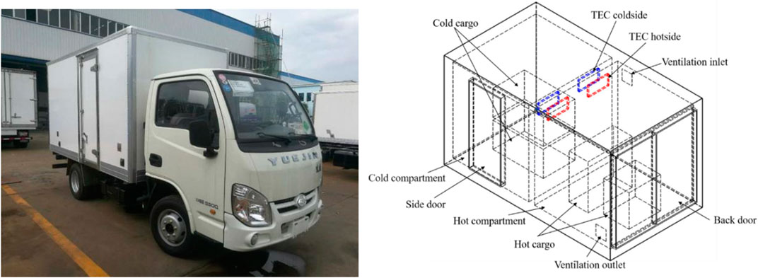
FIGURE 1. Insulated van and Dual temperature zone insulated compartment model.
The compartment is made of polyurethane material with a density of 40 kg/m³, a specific heat capacity of 1380 J/kgK, and a specific heat capacity of 0.04 W/m K. The thickness of the compartment is 50 mm, and the thermoelectric cooling device is placed on the partition of the two temperature zones, and the fans are used to force heat exchange to accelerate the air flow in the compartment. In order to prevent the high temperature of the space in the hot zone from affecting the refrigeration performance, a ventilation port is installed in the hot zone. In order to have a better contrast, the goods are stacked and placed side by side as shown in Figure 2. The goods in the cold zone are fruits and vegetables, in Table 1, the fresh-keeping temperature of several common fruits and vegetables are shown, the sizes of them are 800 × 500 × 400 mm. The goods in the hot zone are high-temperature takeaway food, the size of them are 500 × 400 × 500 and 700 × 300 × 600 mm. The compartment simulates the delivery work at an ambient temperature of 300 K. The goods in the cold zone are taken out of the cold storage at 285 K according to the insurance temperature of common fruits and vegetables, and the goods in the hot zone are placed in the compartment at 320 K. The entire delivery time is 2.5 h (9000 s).
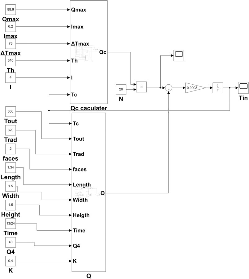
FIGURE 2. Thermal equilibrium.
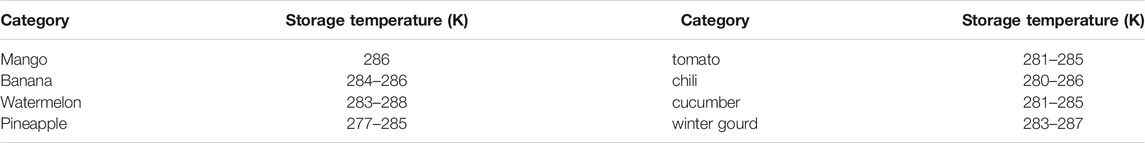
TABLE 1. The fresh-keeping temperature of several common fruits and vegetables (Wenku Baidu, 2021).
The cargo in the hot zone is not sensitive to temperature requirements, and the temperature fluctuation in the hot zone is small. This article mainly studies the air temperature and cargo temperature in the cold zone.
First calculate the heat load in the cold zone:
1) Heat transferred from the outside of the vehicle to the inside of the vehicle through the insulated wall
Heat transfer coefficient of refrigerated compartment
2) Heat transferred from the air leakage into the insulated compartment
In the formula, β is Multiples of compartment air leakage, When the heat transfer area of the car body<20 m2, β ≤ 2.1 h-1, L is latent heat of vaporization (J/kg),
3) Heat transferred from solar radiation into the insulated compartment
4) Heat introduced when the door is opened when loading and unloading goods
In the formula,
5) Heat production of cargo in the compartment
Since the loaded goods are fruits and vegetables, taking bananas as an example, the heat generated by breathing needs to be considered, then
6) Heat production of cabin lights and fans
In the formula,
7) Heat consumed when the van compartment is pre-cooled
The pre-cooling capacity may not be included in the running work, then
8) Heat consumed when the cargo is pre-cooled
Since the goods come from cold storage and do not need to be pre-cooled, then
So, the cooling power demand is
In order to ensure sufficient refrigeration power, safety factor n should be considered when designing and selecting refrigeration power. Generally, n = 1.3–1.5 for small refrigerated trucks. Taking n = 1.5, the required cooling power is
Mathematical Model
Comparing two commonly used thermoelectric cooling modules, the rated voltage is 6A, 12,706 is composed of 127 PN type semiconductors, and 19,906 is composed of 199 PN type semiconductors, the parameters are shown in the Table 2. Due to the greater number of PN type semiconductors and semiconductor materials with greater merit coefficient, 19,906 has a large cooling capacity and a larger cooling temperature difference. Due to the setting of hot and cold dual temperature zones, the temperature difference between the cold side and hot side is too large. In order to make the cold side have a sufficiently low cooling temperature, the model 19,906 thermoelectric cooling module is selected (Hu et al., 2018; TECooler, 2021).
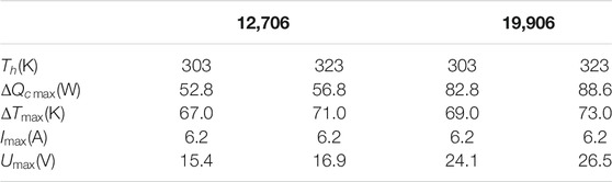
TABLE 2. The parameters of Two kinds of thermoelectric cooling modules.
The simplified energy equilibrium model, it has been used and validated by many researchers (Palacios et al., 2009; Chen and Snyder, 2013; Russel et al., 2013; Zhao and Tan, 2014) as shown below:
The cooling power of the thermoelectric cooling module can be obtained by Equation 11, and the input power of the thermoelectric module can be obtained by Eq. 12. where,
Thermoelectric module
Alternatively. Since thermoelectric cooling modules consists of a bunch of thermoelements. Thus, the other way to obtain thermoelectric module cooling power (
The temperature of the in insulated compartment is achieved by adjusting the cooling power or heating power to balance with the required cooling or heating power to reach a stable temperature. According to the energy balance equation and the basic theoretical equation of thermoelectric cooling, the following system mathematical model is obtained.
Heat balance equation of compartment:
Dynamic equation:
Stable equation:
To build a mathematical model in MATLAB. Considering the cooling speed and requiring cooling as fast as possible, so build a numerical simulation model in MATLAB based on the above equation of state. It is concluded that when 20 thermoelectric cooling modules are arranged, the temperature can reach stability within 4 min.
In order to get the optimal working range of the thermoelectric cooling module. Numerical calculations are performed on the working current conditions of 1–6 A, and the changes of the compartment temperature, the cooling capacity of the single-chip thermoelectric cooling module and the COP of the thermoelectric cooling module with the time are obtained, and the results are shown in the Figures 3, 4. Finally, the stable temperature of the carriage, the maximum cooling capacity of the single-chip thermoelectric cooling module and the curve of the stable COP value with the current change are shown in the Figure 5.
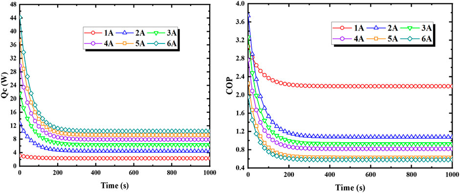
FIGURE 3. The variation of Single-chip TEM cooling power and COP with time in different currents.
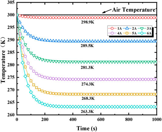
FIGURE 4. The variation of compartment temperature with time in different currents.
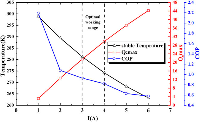
FIGURE 5. The variation of stable temperature, maximum cooling capacity and COP of the refrigeration device with current in the compartment.
As shown in the figure, the results of the numerical model show that as the current increases, the maximum cooling capacity increases, and the stable temperature in the compartment decreases, but the COP value of the thermoelectric cooling device decreases. This is because the temperature difference between the cold and hot sides increases, Thomson heat increases at the same time, the increase in current leads to an increase in Joule heat and a sharp decrease in cooling efficiency. Comprehensively considering the cooling effect, cooling temperature and cooling efficiency of the thermoelectric cooling module, the best working current of the thermoelectric cooling module is 3–4 A.
Considering the temperature of the cargo in the compartment of the insulted vans, the requirement is below 280 K, and the lower the temperature, the faster the cooling speed. Based on the actual situation, this article sets the current at 4 A for simulation. At this time, according to the calculation results of the mathematical model, the maximum cooling power of the thermoelectric cooling device is 29.8 W, the stable COP value will be 0.82, and the stable temperature in the compartment will reach 274.3 K. When working under this condition, sufficient cooling capacity can be ensured, the stable temperature in the compartment is ideal, and the COP can be as high as possible.
Design and Analysis of Thermoelectric Cooling Device
The performance of the thermoelectric cooling device directly determines the refrigeration effect of the refrigeration system. This chapter studies the refrigeration performance of thermoelectric cooling devices (Seo et al., 2018; Chen and Snyder, 2013; Saifizi et al., 2018).
The size of each thermoelectric cooling module is 40 × 40 × 3.7 mm, the size of water tank is 160 × 40 × 20 mm, the size of radiator is 250 × 120 × 20 mm. As Figure 6 shown, the heat exchange method of the hot side of the thermoelectric cooling device adopts water-cooled circulation heat exchange, and the cold side adopts forced convection heat exchange. In order to ensure good heat transfer efficiency, use a clamping device to dissipate the finned heat sink, the thermoelectric cooling modules and the water tank are clamped (Han and Wang, 2021). The water tank flows the heat into the radiator through the water pipe to dissipate the heat and sends the heat to the hot zone; the cold side is radiated by the fan on the surface of the finned heat sink, and the cold air is sent into the cold zone. The whole device is fixed on the partition of the cold and hot temperature zone (Boccardi et al., 2019). Use Flotherm to perform steady-state simulation of the thermoelectric cooling device, and the temperature cloud diagram under the refrigerator is shown in Figure 7B.
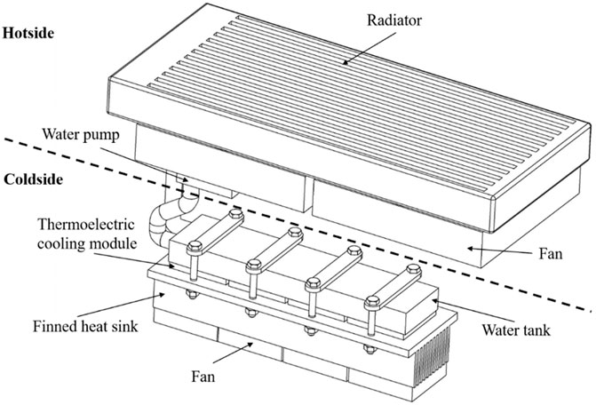
FIGURE 6. Thermoelectric cooling device model.
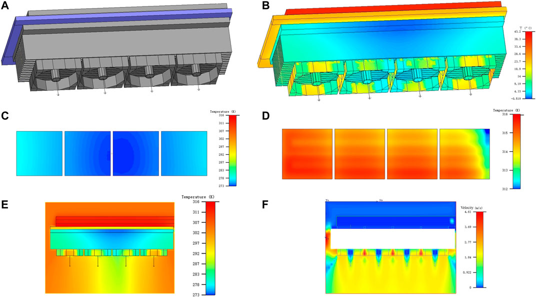
FIGURE 7. Performance analysis of thermoelectric cooling device.
A steady-state analysis has been made. Four thermoelectric cooling modules were installed in the thermoelectric cooling device, and the surface temperature field of the hot side and cold side were analyzed. The temperature field of the hot side and the cold side are shown in the Figure 7C and Figure 7D, the temperature of the middle surface is shown in Figure 7E, and the speed of the middle surface is shown in the Figure 7F when the surface temperature was stable.
It can be seen from the figure that the cold side temperature of the thermoelectric cooling modules at both ends is 274–276K, and the cold side temperature of the two thermoelectric cooling modules in the middle is 272–273 K. For the four thermoelectric cooling modules, the cold side temperature of the two thermoelectric cooling modules at the both ends are higher than that in the middle. TEM1 has a higher temperature than TEM4, and TEM2 has a higher temperature than TEM4. This is because the right thermoelectric cooling modules are closer to the inlet of water. At the water inlet of the hot water tank, the cooling water takes away the heat generated by the hot side of the right thermoelectric cooling module and the water temperature rises, so that the heat exchange capacity of the hot side of the left thermoelectric cooling module decreases and the cooling capacity of the left thermoelectric cooling module decreases.
It can be seen from the simulation that the cooling performance of the thermoelectric cooling module meets the conditions, the cold side temperature meets the cooling temperature requirement of 274.3 K, and the cooling capacity reaches the design requirement of 29.8 W.
The data obtained in Flotherm post-processing is shown in Table 3.

TABLE 3. The TEM date from Flotherm post-processing.
Simulation Results
The numerical simulation calculation method used by Fluent is the finite volume method (FVM). The turbulence models provided by Fluent include: single equation (Spalart-Allmaras) model, two equation model (Standard
In order to accurately analyse the airflow state inside the carriage, a suitable turbulence model needs to be selected. Fluent contains two equation turbulence models such as
The control equation of the turbulence model is:
Fluid motion must follow the laws of conservation of physics. These laws include the law of conservation of mass, the law of conservation of momentum, and the law of conservation of energy. If the flow involves the mixing or interaction of different components, the law of conservation of components must also be followed. In actual calculations, different flow regimes must also be considered. For example, turbulence must follow additional turbulence equations.
The differential form of the continuity equation of hydromechanics:
The differential form of the momentum equation of hydromechanics:
The differential form of the energy equation of hydromechanics:
In the formula,
For the convenience of calculation, the following assumptions are made for the model: the air inside the compartment is a radiant transparent medium, which is incompressible and consistent; the walls of the compartment are insulated and the compartment is well-sealed, there is no air leakage; the air in the compartment is Newtonian fluid, the cargo area is regarded as a porous medium; the influence of moisture loss and latent heat of vaporization in the cargo area on the temperature of the cargo is not considered; the influence of temperature changes on the physical parameters of the air and cargo is ignored; the pipes and guide rails in the refrigerated truck and the experimental platform used for building the experiment platform are ignored The effect of iron wire on airflow (Tso et al., 2002).
The simplec algorithm is selected for iterative calculation. Compared with the simple algorithm, the simplec algorithm may get better results on many problems, and the convergent solution will be obtained faster. This time in simplec, the sub-relaxation factor of the pressure correction is set to 1.0. After detecting the mesh and boundary conditions, redefining the size of the model, and smoothing the mesh, the meshing is shown in Figure 8, it is necessary to define various parameters of the model in detail:
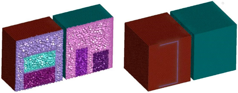
FIGURE 8. Meshing model.
Simulation boundary condition setting: It simulates an unsteady state process, the insulated compartment is made of polyurethane foam material, the thickness of the insulated compartment is 50 mm, and the outdoor temperature is set to 300 K. The cargo is set in porous media. The cold zone cargo takes banana as an example. The water content is 74.8%, the thermal conductivity is 0.465 W/m K, the breathing heat is 60 W/m3, the specific heat capacity is 3120 J/kg K, the density is 813 kg/m3, and the initial temperature is 285 K. The goods in the hot zone are high-temperature food as an example. The thermal conductivity is 0.3 W/m K, the specific heat capacity is 3500 J/kg K, the density is 750 kg/m3, and the initial temperature is 320 K. Considering solar radiation, take Wuhan coordinates (114°E longitude, 30°N latitude). The entire transportation process takes 2.5 h (9000 s).
The Figure 9 shows the working condition of the thermoelectric cooling system not working. The changes of hot and cold zone temperature and cargo temperature with time of double temperature zone without refrigeration system were simulated. At the beginning, the temperature in the compartment dropped rapidly because of the low-temperature cargo in the cold zone. As time went by, the cargo breathed heat, and the heat transferred into the compartment through the insulating wall and solar radiation heat continued to increase, and the temperature inside the compartment began to rise, the temperature inside the compartment rose to 297.3 K within 2.5 h, the temperature of the cargo slowly increased from the initial temperature of 285–290.8 K, and the temperature floated at 5.8 K.
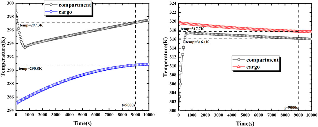
FIGURE 9. The variation of dual zone temperatures and cargo temperatures with time.
In the hot zone, the temperature inside the compartment rises rapidly because of the high-temperature cargo. Because the heat leakage is greater than the radiation heat, the temperature in the compartment decreases slowly. The temperature of the cargo decreases slowly from the initial temperature of 320–317.7 K, and the temperature fluctuates at 2.3 K.
Refrigeration condition 1: Thermoelectric cooling module were used as heat source output, UDF was used to write control codes, and the temperature of the hot and cold surfaces of the thermoelectric cooling module were collected. The cooling capacity and heating capacity were set by formulas
The Figure 10 shows the temperature change of the middle surface of Y = 0.75 m, which simulates the change of the temperature field in the compartment 40 min before the real cooling situation.
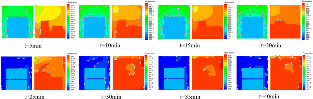
FIGURE 10. The temperature field of the compartment at y = 0.75 m in the first 40 min.
The Figure 10 is a graph of the temperature change in the compartment of a complete refrigeration cycle. Within 0–20 min, the compartment is in a heat preservation state. It can be seen that the initial temperature in the compartment is 300 K. After the cargo are put in, the cargo in the compartment and the air conduct heat conduction. The air temperature in the compartment drops rapidly and then starts to rise slowly, while the temperature of the cargo is guaranteed to rise slowly. When it reaches 20 min, the refrigeration system starts to work. Due to the high heat transfer coefficient and low specific heat capacity of the air, the ambient air in the compartment cools down quickly, and the temperature of the cargo begins to drop after the air cools down.
Result analysis: As shown in Figure 11. The temperature of the cargo at the cold side showed an oscillating increase, and the temperature of the cargo in the compartment reached the maximum at the 8460 s, which was 286.5 K, an increase of 1.5 K. During the entire transportation process, it stops working for 80 min within 2.5 h, and the thermoelectric refrigeration system works for 70 min.
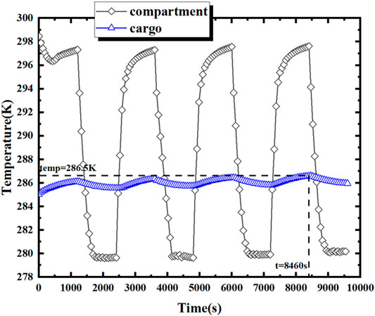
FIGURE 11. Cooling condition 1.
Set up another cooling condition 2 for comparison: Thermoelectric cooling module were used as heat source output, UDF was used to write control codes, and the temperature of the hot and cold surfaces of the thermoelectric cooling module were collected. The cooling capacity and heating capacity were set by formulas
Result analysis: As shown in Figure 12. In 0–840 s, the situation is preserving heat, and the refrigeration system does not work. The thermoelectric cooling system starts to work when the temperature rises to 286.2 K. At 2700 s, the temperature is close to the initial temperature of the cargo and stops thermoelectric cooling system working, and the temperature of the entire cargo stabilizes at 285–286.2 K. Within 2.5 h, the thermoelectric cooling system works for 92 min in total, and the temperature fluctuation can be maintained within 1.2 K.
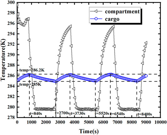
FIGURE 12. Cooling condition 2.
Conclusion
This paper has established the physical model and mathematical model of the home delivery insulated vehicle, build a Simulink numerical calculation simulation model, obtained the best working range of the thermoelectric cooling module, designed the thermoelectric cooling device for the compartment and analyzed the refrigeration performance of it, finally, simulated internal flow field and temperature field of the whole vehicle with or without thermoelectric cooling system in the real 2.5-h delivery process.
This system can reduce the temperature fluctuation of cargo in the two compartments. In this case, during the 2.5 h distribution process without thermoelectric cooling system, the temperature of the cargo in the hot zone fluctuates by 2.3 K, and the temperature of the cargo in the cold zone fluctuates by more than 5.8 K. After adding the thermoelectric cooling system, the temperature fluctuation of the hot zone is 2 K, which is reduced to 13%, and the temperature fluctuation of the cargo in the cold zone is 1.5 K, which is a reduction of 74%. It is suitable for the transportation of cargo with strict requirements on temperature preservation. In this case, the temperature control is within 1.5 K as an example. When the temperature control fluctuates less, the working time of the thermoelectric cooling system will increase drastically, resulting in a sharp deterioration in economy.
Therefore, it is feasible to use the thermoelectric cooling system on the short-distance insulated distribution vehicle, and it can be realized on the vehicle with the cold and hot dual temperature zone. It is most suitable that the temperature in the cold zone is 280–300 K and the temperature difference between the hot and cold zones is within 50 K. If the temperature in the cold zone is lower, or the temperature difference between the hot and cold zones is more than 50 K, the cooling performance of the unipolar thermoelectric cooling modules cannot meet the demand.
The work that will be carried out after this research includes: 1. Do experiments to verify the research results. 2. Study how to reduce the energy consumption of thermoelectric cooling system when the insulation conditions are met. 3. The influence of the position of the thermoelectric cooling device in the compartment on the refrigeration effect should be study.
Data Availability Statement
The original contributions presented in the study are included in the article/supplementary material, further inquiries can be directed to the corresponding author.
Author Contributions
The review and verification of the paper are completed by X-HY, the simulation and writing are completed by C-HQ, the data analysis is completed by Y-PW, and the proposal and improvement of the argument are completed by XL.
Funding
This work was supported by National Natural Science Foundation of China (Grant No. 51805387 and No. 51775395), State’s Key Project of Research and Development Plan (Grant No. 2018YFB0105301) and the Fundamental Research Funds for the Central Universities (WUT: 2017II18XZ), and the 111 Project (B17034).
Conflict of Interest
The authors declare that the research was conducted in the absence of any commercial or financial relationships that could be construed as a potential conflict of interest.
Publisher’s Note
All claims expressed in this article are solely those of the authors and do not necessarily represent those of their affiliated organizations, or those of the publisher, the editors and the reviewers. Any product that may be evaluated in this article, or claim that may be made by its manufacturer, is not guaranteed or endorsed by the publisher.
References
Ahmed, M., Meade, O., and Medina, M. A. (2010). Reducing Heat Transfer across the Insulated walls of Refrigerated Truck Trailers by the Application of Phase Change Materials. Energ. Convers. Manag. 51, 383–392. doi:10.1016/j.enconman.2009.09.003
Astrain, D., Vián, J. G., and Albizua, J. (2005). Computational Model for Refrigerators Based on Peltier Effect Application. Appl. Therm. Eng. 25, 3149–3162. doi:10.1016/j.applthermaleng.2005.04.003
Astrain, D., Vián, J. G., and Domı́nguez, M. (2003). Increase of COP in the Thermoelectric Refrigeration by the Optimization of Heat Dissipation. Appl. Therm. Eng. 23, 2183–2200. doi:10.1016/s1359-4311(03)00202-3
Boccardi, S., Ciampa, F., and Meo, M. (2019). Design and Development of a Heatsink for Thermo-Electric Power Harvesting in Aerospace Applications. Smart Mater. Struct. 28, 105057. doi:10.1088/1361-665x/aacbac
Bulat, L., and Nekhoroshev, V. (2003). “Thermoelectric Cooling-Heating Unit For Thermostatic Body of Pickup Refrigerated Trucks,” in Proceedings ICT'03. 22nd International Conference on Thermoelectrics, La Grande Motte, France, August 17–21, 2003. doi:10.1109/ICT.2003.1287596
Cai, Y., Wang, Y., Liu, D., and Zhao, F.-Y. (2019). Thermoelectric Cooling Technology Applied in the Field of Electronic Devices: Updated Review on the Parametric Investigations and Model Developments. Appl. Therm. Eng. 148, 238–255. doi:10.1016/j.applthermaleng.2018.11.014
Chen, M., and Snyder, G. J. (2013). Analytical and Numerical Parameter Extraction for Compact Modeling of Thermoelectric Coolers. Int. J. Heat Mass Transfer 60, 689–699. doi:10.1016/j.ijheatmasstransfer.2013.01.020
Choi, H.-S., Yun, S., and Whang, K.-i. (2007). Development of a Temperature-Controlled Car-Seat System Utilizing Thermoelectric Device. Appl. Therm. Eng. 27, 2841–2849. doi:10.1016/j.applthermaleng.2006.09.004
Dai, Y. J., Wang, R. Z., and Ni, L. (2003). Experimental Investigation and Analysis on a Thermoelectric Refrigerator Driven by Solar Cells. Solar Energ. Mater. Solar Cell 77, 377–391. doi:10.1016/s0927-0248(02)00357-4
Ebale, L. O., Pierre Gomat, L. J., Nzonzolo, L., Mavoungou, M. R., and Kibongani, F. (2019). Optimization of a Thermoelectric Cooling System with Peltier Effect. Am. J. Energ. Eng. 7 (3), 55–63. doi:10.11648/j.sjee.20190703.12
Enescu, D., and Virjoghe, E. O. (2014). A Review on Thermoelectric Cooling Parameters and Performance. Renew. Sustain. Energ. Rev. 38, 903–916. doi:10.1016/j.rser.2014.07.045
GENTHERM (2014). The Thermal Comfort of Drivers in the Vehicle. Available at: http://www.gentherm.com/page/thermal-management-applications (Accessed January, 2014).
Han, X., and Wang, Y. (2021). Experimental Investigation of the thermal Performance of a Novel Split-type Liquid-Circulation Thermoelectric Cooling Device. Appl. Therm. Eng. 194, 117090. doi:10.1016/j.applthermaleng.2021.117090
Hu, J.-Z., Liu, B., Zhou, J., Li, B., and Wang, Y. (2018). Enhanced Thermoelectric Cooling Performance with Graded Thermoelectric Materials. Jpn. J. Appl. Phys. 57, 071801. doi:10.7567/jjap.57.071801
Liang, K., Li, Z., Chen, M., and Jiang, H. (2019). Comparisons between Heat Pipe, Thermoelectric System, and Vapour Compression Refrigeration System for Electronics Cooling. Appl. Therm. Eng. 146, 260–267. doi:10.1016/j.applthermaleng.2018.09.120
Luo, Q., Wang, Y., and Zhang, P. (2010). “A Novel Thermoelectric Air-Conditioner for a Truck Cab,” in International Conference on Advances in Energy Engineering, doi:10.1109/icaee.2010.5557585
Moureh, J., Menia, N., and Flick, D. (2002). Numerical and Experimental Study of Airflow in a Typical Refrigerated Truck Configuration Loaded with Pallets. Comput. Electron. Agric. 34, 25–42. doi:10.1016/s0168-1699(01)00178-8
Moureh, J., Tapsoba, S., Derens, E., and Flick, D. (2009). Air Velocity Characteristics within Vented Pallets Loaded in a Refrigerated Vehicle with and without Air Ducts. Int. J. Refrig. 32, 220–234. doi:10.1016/j.ijrefrig.2008.06.006
Ngo, T.-T., Wang, C.-C., Chen, Y.-T., and Than, V.-T. (2021). Developing a Thermoelectric Cooling Module for Control Temperature and thermal Displacement of Small Built-In Spindle. Therm. Sci. Eng. Prog. 25, 100958. doi:10.1016/j.tsep.2021.100958
Nunes, M. C. N., Emond, J. P., Rauth, M., Dea, S., and Chau, K. V. (2009). Environmental Conditions Encountered during Typical Consumer Retail Display Affect Fruit and Vegetable Quality and Waste. Postharvest Biol. Techn. 51, 232–241. doi:10.1016/j.postharvbio.2008.07.016
Oró, E., Miró, L., Farid, M. M., and Cabeza, L. F. (2012). Thermal Analysis of a Low Temperature Storage Unit Using Phase Change Materials without Refrigeration System. Int. J. Refrig. 35, 1709–1714. doi:10.1016/j.ijrefrig.2012.05.004
Palacios, R., Arenas, A., Pecharromán, R. R., and Pagola, F. L. (2009). Analytical Procedure to Obtain Internal Parameters from Performance Curves of Commercial Thermoelectric Modules. Appl. Therm. Eng. 29, 3501–3505. doi:10.1016/j.applthermaleng.2009.06.003
Russel, M. K., Ewing, D., and Ching, C. Y. (2013). Characterization of a Thermoelectric Cooler Based thermal Management System under Different Operating Conditions. Appl. Therm. Eng. 50, 652–659. doi:10.1016/j.applthermaleng.2012.05.002
Saifizi, M., Lee, T. W., Anuar, S. N. N., Zunaidi, I., Diana, N. S., Mustafa, W. A., et al. (2018). Development and Investigation of Thermoelectric Cooling Performance Based on Space Scales. IOP Conf. Ser. Mater. Sci. Eng. 429, 012083. doi:10.1088/1757-899x/429/1/012083
Seo, Y. M., Ha, M. Y., Park, S. H., and Lee, G. H. (2018). A Numerical Study on the Performance of the Thermoelectric Module with Different Heat Sink Shapes. Appl. Therm. Eng. 128, 1082–1094. doi:10.1016/j.applthermaleng.2017.09.097
Sulaiman, A. C., Amin, N. A. M., Basha, M. H., Majid, M. S. A., Nasir, N. F. b. M., and Zaman, I. (2018). Cooling Performance of Thermoelectric Cooling (TEC) and Applications: A Review. MATEC Web Conf. 225, 03021. doi:10.1051/matecconf/201822503021
TECooler (2021). Optimum Temperature for Some Fruits and Vegetables Storage. Available at: www.TECooler.com (Accessed June, 2021).
Tso, C. P., Yu, S. C. M., Poh, H. J., and Jolly, P. G. (2002). Experimental Study on the Heat and Mass Transfer Characteristics in a Refrigerated Truck. Int. J. Refrig. 25, 340–350. doi:10.1016/s0140-7007(01)00015-9
Villante, C., Anatone, M., and De Vita, A. (2019). A Distributed Parameter Approach for the Modeling of Thermoelectric Devices. SAE Int. J. Engines 12, 45–56. doi:10.4271/03-12-01-0004
Weerasinghe, R., and Hughes, T. (2017). Numerical and Experimental Investigation of Thermoelectric Cooling in Down-Hole Measuring Tools; a Case Study. Case Stud. Therm. Eng. 10, 44–53. doi:10.1016/j.csite.2017.02.002
WENKU BAIDU (2021). Available at: https://wenku.baidu.com/view/8a9addd36edb6f1afe001f6f.html (accessed June, 2021).
You, L., Mohammad Siddique, A. R., Andrew Gadsden, S., and Mahmud, S. (2021). Experimental Investigation of Thermoelectric Cooling for a New Battery Pack Design in a Copper Holder. Results Eng. 10, 100214. doi:10.1016/j.rineng.2021.100214
Zhao, D., and Tan, G. (2014). A Review of Thermoelectric Cooling: Materials, Modeling and Applications. Appl. Therm. Eng. 66, 15–24. doi:10.1016/j.applthermaleng.2014.01.074
Zhao, H., Liu, S., Tian, C., Yan, G., and Wang, D. (2018). An Overview of Current Status of Cold Chain in China. Int. J. Refrig. 88, 483–495. doi:10.1016/j.ijrefrig.2018.02.024
Glossary
Keywords: thermoelectric cooling, temperature control compartment, cold chain logistics, CFD simulation, automobile
Citation: Yuan X-H, Qin C-H, Wang Y-P and Liu X (2021) Characteristics Analysis of Small Insulated Vans Based on Thermoelectric Cooling. Front. Energy Res. 9:740748. doi: 10.3389/fenrg.2021.740748
Received: 13 July 2021; Accepted: 30 August 2021;
Published: 10 September 2021.
Edited by:
Fu-Yun Zhao, Wuhan University, ChinaReviewed by:
Liang Li, University of Hertfordshire, United KingdomFubin Yang, Beijing University of Technology, China
Xinzhi Huang, Wuhan University, China
Yulong Zhao, Hebei University of Technology, China
Jinghui Meng, North China Electric Power University, China
Copyright © 2021 Yuan, Qin, Wang and Liu. This is an open-access article distributed under the terms of the Creative Commons Attribution License (CC BY). The use, distribution or reproduction in other forums is permitted, provided the original author(s) and the copyright owner(s) are credited and that the original publication in this journal is cited, in accordance with accepted academic practice. No use, distribution or reproduction is permitted which does not comply with these terms.
*Correspondence: Xun Liu, bGl1eHVuQHdodXQuZWR1LmNu