 Jingbo Zhao*
 Yan Tao
- State Grid Jiangsu Electric Power Co., Ltd, Research Institute, Nanjing, China
The hybrid HVDC with cascaded multi-infeed MMC inverters is proposed in recent years and it will be put into reality in near future. But the control characteristic of this hybrid HVDC have not been discussed in details. This paper investigates the control strategy characteristic of the hybrid HVDC using cascaded multi-infeed MMC inverters. By combining the UI curves (the DC voltage and DC current curves) of LCC rectifiers, LCC inverter and MMC inverters, the complete UI curves of the hybrid HVDC are obtained in different control modes. Through the complete UI curve, the characteristic of the control strategy is investigated in different operation situations. It is found that the MMC inverter in DC voltage control could shift to the rectifying mode if the fault occurs or active power orders are intensively changed. To solve such problem, the coordinated control strategy based on the dynamic limiter, diodes and LCC-MMC active orders is proposed in this paper, which can not only prevent the MMC inverter from becoming a rectifier at DC side but also can improve the AC side voltage stability. Nevertheless, the proposed strategy can further endow the MMC with fault ride through abilities. The simulations in PSCAD software verify the correctness and effectiveness of the proposed control strategy.
Introduction
The hybrid high voltage direct current (HVDC) transmission technology combines the advantages of line commutated converters (LCC) and voltage sourced converters (VSC), hence it is proposed in the past years and has become a new direction of HVDC technology (Qahraman, 2010).
Generally, the hybrid HVDC can be divided into three types according to the topologies shown in Figure 1 (Lou et al., 2019). The first type in shown in Figure 1A is the hybrid HVDC with LCC at rectifier and MMC at inverter. This kind of hybrid HVDC represents the original combination concept between VSC and LCC. Based on type (A) structure, by further modifying its VSC inverter, a lot of similar hybrid HVDCs are investigated in the past. Such as the ultra-high voltage hybrid HVDC with a bipolar structure (Yang et al., 2019), the hybrid HVDC for renewable power transmission (Torres-Olguin et al., 2013), and the hybrid HVDC with clamped double sub-modules modular multi-level converters (MMC) (Xue et al., 2019). Although the structures of these hybrid HVDCs are varied, the control strategy of them is not much complex, of which the VSC inverter is usually operating in constant DC voltage control and the LCC rectifier retains the original control configuration (Shu et al., 2019).
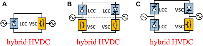
FIGURE 1. The three type hybrid HVDCs with different topologies. (A) type (A) hybrid HVDC (B) type (B) hybrid HVDC (C) type (C) hybrid HVDC.
However, the type (A) hybrid HVDC usually suffers from the power limitation of its VSC inverter, which has much smaller rated capacity compared to the LCC converter. To overcome this shortage, one solution is to add more VSC inverters and let the type (A) hybrid HVDC become a multi-terminal DC grid, which has been realized in the Wudongde hybrid HVDC project in China (Rao et al., 2019). Another solution is letting the LCC be in series with VSC at both rectifier side and inverter side (Xiang et al., 2020), which is the second type hybrid HVDC as shown in Figure 1B. In such a topology the capacity of the whole hybrid HVDC system can be enlarged and the commutation failure risk of the LCC inverter can also be significantly decreased (Xiao et al., 2017). For this kind of hybrid HVDC, the active power control strategy is also simple and clear, which is inverters in constant DC voltage control and rectifiers in constant active power or current control (Kaur and Chaudhuri, 2019). The main attention on type (B) hybrid HVDC is concentrated on the receiving AC side, as there is the AC voltage stability and the reactive power interaction mechanism issues between the VSC and LCC (Guo et al., 2012; Li et al., 2017; Ni et al., 2018; Zou et al., 2018; Xiao et al., 2019).
To further reduce the cost, the type (C) hybrid HVDC shown in Figure 1C with only one VSC inverter is studied (Qahraman and Gole, 2005), which has similar active power control strategy with type (B) hybrid HVDC. However, the VSC inverter in type (C) hybrid HVDC would also limit the maximum transmitted active power as it is in series with the LCC inverter. By considering the bulk capacity and reasonable economical cost, some researchers have proposed another new type hybrid HVDC with cascaded multi-infeed MMC inverters in last 2 years (Chen et al., 2019)- (Liu et al., 2018), which is shown in Figure 2. Obviously, this new hybrid HVDC is developed from the type (c) structure, where the single VSC inverter is replaced by several paralleled MMC inverters, such that more active power can be transmitted. On the other side, the LCC inverter and MMC inverters are infeeding into different AC areas rather than into one location. Thus, the flexibility and reliability can be highly increased both in the preliminary construction and the in later operation. Due to the above advantages, the State grid corporation of China, which is the biggest power company in China, has planned to construct such a hybrid HVDC project in the near future.
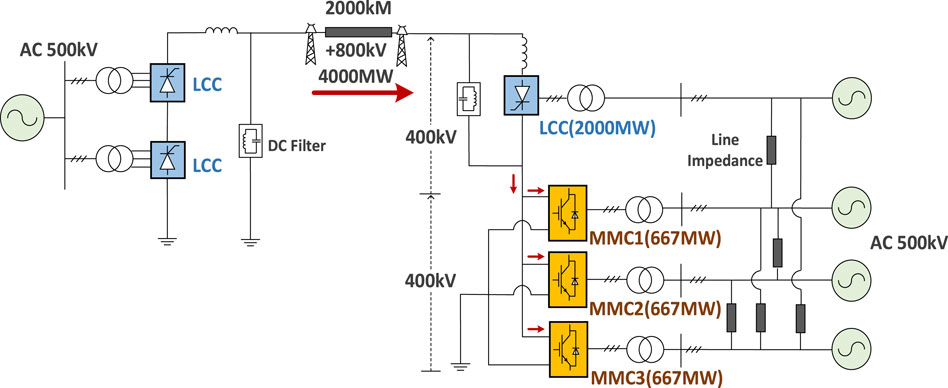
FIGURE 2. Hybrid HVDC with cascaded multi-infeed MMC inverters.
However, for such an important and practical hybrid HVDC, the specific active power control strategy and its characteristic have not been studied in details, and only a few simulations analysis are reported (Chen et al., 2019)- (Liu et al., 2018). Although some papers have studies the HVDC control strategies in hybrid situations, most of them are concentrated on the classical hybrid styles in Figures 1A,B. Such as the droop coefficients design method in hybrid multi-terminal HVDC systems (Lee et al., 2020), the power reversal strategies for hybrid LCC/MMC HVDC systems (Li et al., 2020), and the fault ride-through methods of hybrid VSC-LCC multi-terminal HVDC transmission systems (Haleem et al., 2019). In cascaded situation the control and operating modes are discussed (Xiang et al., 2020), but the topology is different and its control characteristic are neither the same. Actually, in this new hybrid HVDC structure, by introducing multi-infeed MMCs has changed it from a traditional hybrid HVDC to a multi-terminal system. This makes the control strategies of the hybrid HVDC with cascaded multi-infeed MMC inverters to be very different from the point-to-point hybrid HVDC system. Because the increased MMCs endow the VSC inverters with inner power distribution abilities rather than a pure constant DC voltage control station. Simultaneously, the extra obtained ability increases its operation complexity, and how the active power is distributed between multi-MMC inverters and what the impact is should also be clarified.
To investigate the detailed control characteristic of the hybrid HVDC with cascaded multi-infeed MMC inverters, this paper analyzes the control strategy characteristic of the hybrid HVDC and designs the dynamic coordinated control strategy to improve its stability performance. The organization of this paper is as follows. The Hybrid High Voltage Direct Current With Cascaded Multi-Infeed MMC Inverters introduces the topology and control strategies of hybrid HVDC with cascaded multi-infeed MMC inverters. The UI Curves of Hybrid High Voltage Direct Current for Different Control Strategies obtains hybrid HVDC’s complete DC voltage and DC current curves (UI curves) through theoretical analysis. Based on the obtained UI curves, The Control Characteristic Analysis and Coordinated Strategy Design analyzes the control characteristic of the hybrid HVDC system and designs the dynamic coordinated strategy. Simulation Verifications validates the theoretical analysis by simulations. Finally, Conclusion gives suggestions and concludes the paper.
The Hybrid High Voltage Direct Current With Cascaded Multi-Infeed MMC Inverters
The structure of a hybrid HVDC with cascaded multi-infeed MMC inverters is presented in Figure 2. It can be seen that the rated power and voltage of the hybrid HVDC are 4000 MW and 800 kV, where three 400 kV/677 MW MMC inverters are in series with a 2000 MW LCC. The MMCs are all half-bridge inverters and infeeding into different AC areas, which are connected through varied distances.
The Control Strategies of Line Commutated Converters
The control strategies of LCC are composed of two parts, which are the rectifier control strategy and the inverter control strategy. For a classical LCC HVDC transmission system with 800 kV rated voltage, the UI curves of rectifier and inverter can be drawn as shown in Figure 3 (Arrillaga, 1998).
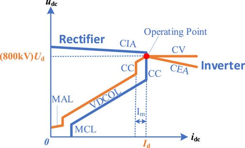
FIGURE 3. Classical control strategies of LCC HVDC where the abbreviated control modes can be found in Table 1.
In Figure 3, the blue curve represents the UI characteristic of rectifier operation, and the yellow curve represents the inverter characteristic. The detailed descriptions of different control modes for each line segment are presented in Table 1, which are all classical control strategies in LCC HVDC system. Ud and Id are the corresponding DC voltage and DC current in the red operating point.
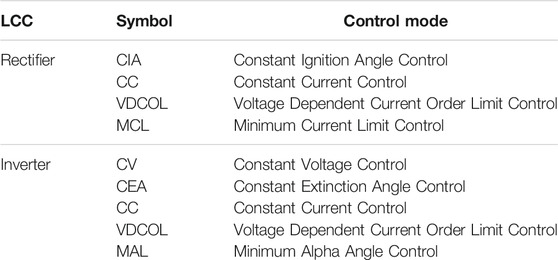
TABLE 1. The control modes of LCC rectifier and inverter.
The Control Strategies of MMC
As for the control strategies of the three MMC inverters, the active power control mode can be varied, because these MMCs have formed a multi-terminal DC grid. Thus, all the control strategies suitable for a DC grid can be applied to the MMC inverters of the proposed hybrid HVDC. Generally, the DC grid active power control strategy can be divided into droop control mode and master-slave control mode, which are based on the combination of constant DC voltage control, droop control, constant active power control and island control (VF control). Because the hybrid HVDC’s MMC inverters are not connected to a passive network according to Figure 2, the island control mode is not considered in this paper. On the other side, the droop control is not suitable for accurate power distribution and would lead to DC voltage fluctuation in practical operation. Thus, the master slave control strategy is selected for investigation, as shown in Table 2.
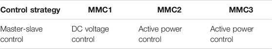
TABLE 2. The typical control modes of MMC inverters.
The UI Curves of Hybrid High Voltage Direct Current for Different Control Strategies
Based on above basic control strategies investigation of the LCC and MMC, this section discusses the whole control characteristic of the complete hybrid HVDC, which is obtained through the UI curve analysis. As the cascaded MMC inverters are the main difference of the hybrid HVDC in this paper from the classical hybrid HVDC, the UI curve analysis are discussed based on different impact to the inverter side and rectifier side.
The Basic Characteristic of Master-Slave Control
When the cascaded MMC inverters are in master-slave control, the DC voltage of MMC is controlled by one inverter, while the other two inverters control their active power as presented in Table 2. Thus, the expression of the MMCs’ UI curve is a line according to the external characteristic of all MMCs, which can be written as
The
Influence to the Line Commutated Converters Inverter UI Curves
According to the characteristic of master-slave control strategy used in MMC inverters, its influence on the UI curves can be obtained by adding the DC voltage control expressions of the LCC and MMC, including all the modes which will impact the DC voltage. Consider that the upper 400 kV LCC inverter in Figure 2 is still in the classical control mode, for each line segment of the LCC inverter UI curve, the expressions of the CV control, CEA control, VDCOL control and MAL control can be written as (see Table 1 for the abbreviations of each control mode)
The
By adding (Eq. 1) to (Eq. 2) to (Eq. 5) successively, the complete DC voltage expressions of hybrid HVDC can be obtained as follows.
Thus, the new UI curves can be drawn according to the above expressions, as the yellow line segments at the left side coordinates shows in Figure 4, which includes the new line segments of MAL′, VDCOL′, CV′ and CEA′ part.
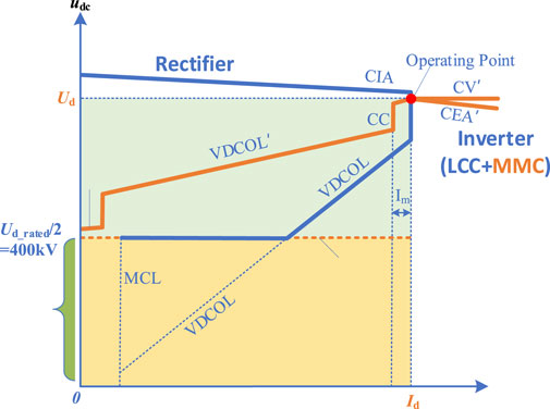
FIGURE 4. Complete UI curves of Hybrid HVDC when MMCs are in Master-slave control (see Table 2).
The Influence on the Rectifier UI Curves
As the MMCs are all inverters, there is little influence to the rectifiers’ UI curves, except that the DC voltage is limited above half of the rated value, which is 400 kV. This is because the half bridge MMC inverter is always in constant DC voltage control mode. Thus, based on the original LCC rectifier UI curves in Figure 3, the new rectifier UI curves of hybrid HVDC are also presented in Figure 4, which are the blue line segments at the left side coordinates.
The Control Characteristic Analysis and Coordinated Strategy Design
Based on the obtained UI curves, the control characteristic of the active power control strategy will be discussed in this section. And the dynamic coordinated control strategy will also be investigated to enhance the system stability when fault happens.
The Static Control Characteristics Analysis
The most important and different static characteristics of the hybrid HVDC control strategy are the active power distribution characteristic between the MMC inverters, and the distribution characteristic between the upper LCC inverter and the lower MMC inverter also.
According to the left part of Figure 4, the active power of the LCC inverter and the MMC inverters are the areas of the upper blue square and the lower yellow square when the system operates at the red point in the UI diagram. It can be seen that the upper blue square area will be influenced both by the operating DC voltage Ud and DC current Id when the control mode of inverters and rectifiers vary. However, the lower yellow square area can only be influenced by the operating DC current Id, because the MMC DC voltage is fixed at the Ud_rated, namely 400 kV. It indicates that more active power of LCC inverter will be changed when the control modes are shifting. Compared to LCC inverter, the MMC inverters can still transmit active power when DC voltage decreases as long as the current order is not zero.
As for the distribution characteristic between the MMC inverters, the master-slave control strategy makes the MMC inverters in constant active power control always to have fixed outputs, while the MMC inverter in constant DC voltage control acts the role of a balance node, as the right side of Figure 4 shows. The sum of the three yellow square areas at the right side coordinates of Figure 4 are the output active powers of three MMC inverters, where the black square area indicates the MMC1 are absorbing active power from AC system when it becomes a rectifier, which may decrease the stability of the receiving end AC system.
The Transient Control Characteristics When Inverter Side Fault Happens
As the topology of the hybrid HVDC is new, its transient characteristic in fault situation needs to be discussed, where the most typical and influential fault, namely the inverter side AC grounding fault, is selected for investigation. It is known that the grounding fault usually leads to voltage decrease in AC system, so the discussion concentrates on the DC side influence.
The Control Modes of Inverters and Rectifiers in Fault
When fault happens at inverter side, the commutation failure will occur in the LCC inverter. Hence the control of LCC inverters will change to the constant extinction angle (CEA) mode, and the operating point will move left side according to the VDCOL current order from rectifiers, where the DC voltage decreases because of the AC fault and it makes the operating point to move downside too, as Figure 5 shows. The most important thing is that because of the DC voltage of MMC inverters cannot be decreased to zero, the whole DC voltage of hybrid HVDC would not be zero either, such that the non-zero current order from rectifiers’ VDCOL curve makes the active power can still be transmitted through the MMC inverters, even when LCC inverters has a commutation failure, where the over current is assumed not enough to block MMC. If the MMCs are blocked, the whole hybrid HVDC would be in outage.
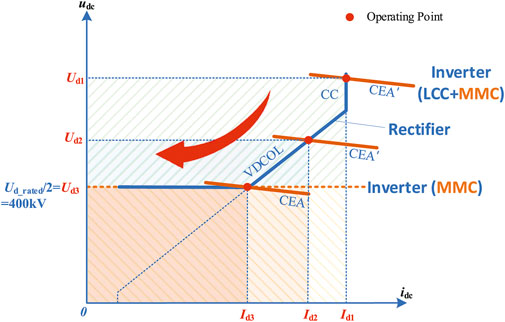
FIGURE 5. Transient characteristic when AC fault happens at inverter side.
The situation of rectifier side AC fault is better than inverter side because no commutation failure could usually happen. Similarly to the conventional LCC HVDC systems, when a rectifier side fault happens, the rectifier would change to constant ignition angle (CEA′) mode and the LCC inverter also changes to constant current (CC) and VDCOL′ control. Such that the current order from LCC inverter curves makes the operating point to move to the left side, and the DC voltage also decreases. The DC voltage can neither be zero because of the MMC inverters, as Figure 6 shows.
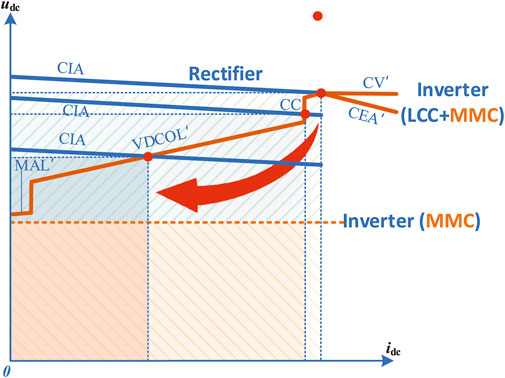
FIGURE 6. transient characteristic when AC fault happens at rectifier side.
The Active Power Distribution of the MMCs
Based on the analysis above, it is known that the MMC1 is possible to become a rectifier as the whole power of three MMCs is actually decided by the orders from LCC rectifiers. If the references of the MMCs in constant active power control are larger than the orders from the LCC rectifiers, the MMC in constant voltage control will rectify the active power from its connected AC system. This situation always occurs when inverter side AC grounding fault happens.
Actually, the current orders from LCC rectifiers will decrease sharply when the AC fault occurs at the inverter side because of the VDCOL control, in which case the MMC in constant DC voltage control could rectify active power from its connected AC system to satisfy the extra active power need of the other two MMCs, as Figure 7 shows.
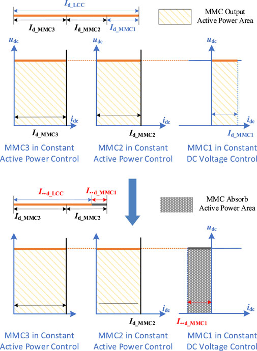
FIGURE 7. The active power distribution characteristic when fault happens at inverter side.
The Coordinated Control Strategy Design for Hybrid High Voltage Direct Current
Thus, it can be clearly seen that the AC grounding fault will not only decrease the voltage and cause LCC commutation failures at AC side, but also leads to the unreasonable active power distribution between MMCs, where the MMC inverter becomes a rectifier would change the power flow intensively at AC side. To solve these problems, the coordinated control strategies need to be designed.
The proposed coordinated control strategies are composed of three parts. The first is the dynamic limiters to enhance MMC’s reactive power supporting ability, which can also prevent the inverter from shifting to a rectifier in some case. The second strategy is the additional diodes devices to further guarantee the inverter operation mode and also can protect the MMC to get through the pole-to-ground fault. And the last strategy is the active power coordinated control between LCC and MMCs.
The Dynamic Limiter
It is known that the current limit of MMC comprises an active current limit and a reactive current limit (Liu and Chen, 2013), which can be given by
According to (Li et al., 2017), designing a dynamic limiter for the MMC in constant active power control can not only enhance AC side voltage stability when fault and disturbance happens but also could limit the active power reference automatically to avoid the MMC in DC voltage control turns to a rectifier. The dynamic reactive current limiter is designed as (Eq. 11) and (Eq. 12) shows.
Where iDlim is the minimum active current limit set to guarantee the necessary active power transmission and
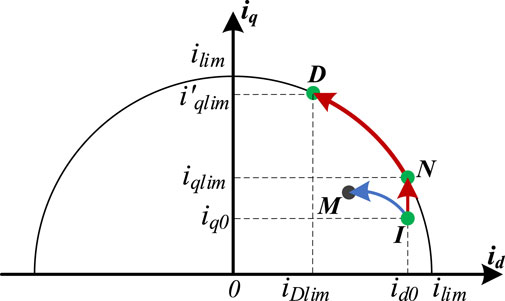
FIGURE 8. The mechanism of the dynamic limiter.
By adding the dynamic limiters to the MMCs in constant active power control, the control characteristic of the hybrid HVDC can be improved.
It can be clearly seen in Figure 8 that when the grounding fault happens at inverter side, the dynamic limiters force the MMCs in constant active power to generate more reactive power
The Additional Diodes Protection Strategy
Although the dynamic limiter is helpful to prevent the inverter from operating in rectifying mode, the inverter in constant DC voltage control will still shift to a rectifier when it is in low power operation. To further guarantee the stability of the hybrid HVDC, the diodes are added as Figure 9 shows. The diodes can make the MMCs always operate in inverter mode. Nevertheless, the diodes can also protect the MMCs from the pole-to-ground fault, because the capacitance discharging path from MMC to DC line is cut off.
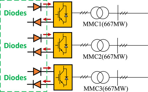
FIGURE 9. The additional diodes protection strategy.
The Coordinated Strategy Between Line Commutated Converters and MMC
Based on the above strategy, the active power thus can only be transferred from DC side to AC side. It is noted that if the active power references of LCC and MMC are not coordinated, the system will still face the stability problems, such as the situation where the LCC decrease its active power while the MMCs remain their previous orders. So, to avoid the instability, the coordinated strategy between LCC and MMC is designed as (Eq. 13) shows. In such strategy, when the MMC and LCC find the orders are not suitable, the active references will be adjusted.
Finally, the whole coordinated control strategy can be described by Figure 10. And the detailed control strategies of each converter can be found in Table 3.
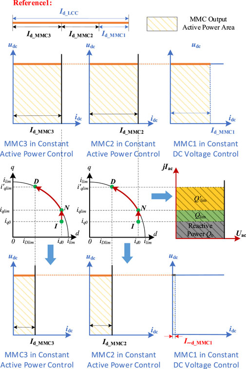
FIGURE 10. The mechanism of the coordinated strategy based on dynamic limiters and diodes.
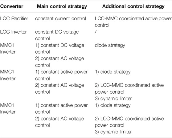
TABLE 3. The control strategies of each converter.
Simulation Verifications
To verify the analysis above, the simulations are implemented in this section, which are used for the validation of dynamic limiters, diodes function, LCC-MMC coordinated strategy and pole-to-ground protection ability respectively. The system parameters can be found in Supplementary Table S1.
Simulation Verification for Dynamic Limiters Strategy
To verify the control characteristic with dynamic limiters, a 0.08s single phase to ground fault happens at the LCC inverter side AC system when t = 2.5 s. The control of the LCC inverter is in constant extinction angle and transfers about 1800MW active power, while the LCC rectifiers are in constant current control. The MMC inverters are in master-slave control as Table 2 shows, each MMC transfers 600MW active power, where the reactive control modes of MMCs are all in constant AC voltage control.
The simulations are implemented when MMC2 and MMC3 are with and without dynamic limiters respectively, where the MMC2 and MMC3 are with a 0.4 p.u. fixed reactive limiter when the dynamic limiters are not added. The simulations results are presented in Supplementary Figures S1–S4 separately.
According to Supplementary Figures S1, S2 it can be clearly seen that the reactive q-axis current limit is enlarged when fault happens, such that much more reactive power can be output by MMC2 and MMC3 to support to connected AC systems.
Nevertheless, it can also be seen from Supplementary Figure S3 that the dynamic limiters simultaneously suppress the active power output of MMC2 and MMC3, such that the MMC1 inverter in DC voltage control will not become a rectifier, which would absorb the active power from inverter side AC system and cause frequency problems. And the DC voltage is slightly more stable when the dynamic limiters are added according to Supplementary Figure S4.
Simulation Verification for Diodes Strategy
To validate the control function of the added diodes, the simulations when the hybrid HVDC is with no additional control, only with dynamic limiters, with both dynamic limiter and diodes are implemented respectively. The simulation settings are basically the same with previous cases, except that the hybrid HVDC is operating in low active power transferring situation.
It can be concluded from Supplementary Figures S5–S7 that, when the hybrid HVDC operates in low power situation, especially, the MMC1 is in low power operation, the dynamic limiter cannot guarantee the inverter mode anymore. Because the MMC1 in constant DC voltage control is near to zero output and can easily become a rectifier. However, when the diodes are added, such problems can be solved and the inverting mode can always be guaranteed according to Supplementary Figure S7.
Simulation Verification for Line Commutated Converters-MMC Coordinated Strategy
The simulation verifications for LCC-MMC coordinated strategy are implemented in this part. In this situation, the simulation settings are similar to the previous Simulation Verification for Dynamic Limiters Strategy, except that the fault at 2.5 s is replaced by the active power order decreasing disturbance of LCC converter. The results with and without LCC-MMC coordinated control are shown in Supplementary Figures S8, S9.
It can be seen that if the coordinated strategy were not added, the DC voltage and the active power of MMC inverter will be forced to decreased, which will deteriorate the system stability.
Simulation Verification for Diodes Protection Ability When Pole-To-Ground Fault Occurs
To further verify the protection ability of diodes in DC fault situation, a pole-to-ground fault is added at 2.5 s. The comparison results in Supplementary Figures 10–12 show that the diodes can effectively cut off the discharging path of the MMCs and help the MMC get ride through the pole-to-ground fault situation. Or that the MMCs will be over current and the hybrid HVDC suffers from instability problems.
Conclusion
This paper studies the coordinated control strategies of hybrid HVDC with cascaded multi-infeed MMC inverters. Based on the theoretical analysis and simulation results, following conclusions can be obtained.
1) The hybrid active power control characteristic can be separated into two parts; the first part is the whole active power transmission characteristic, which is decided by the LCC current orders. The second part is the active distribution part between MMC inverters, which is decided by the active power control strategy both of LCCs and MMCs.
2) In fault and disturbance situations, the MMC inverters can guarantee the DC voltage not to decrease to zero, and the active power can still be transmitted through MMC inverters. But the inverter side grounding fault could intensively change the active power orders, which will let the MMC inverter in constant DC voltage control be operating in rectifier mode if no coordinated control strategy is designed.
3) The dynamic coordinated control strategy proposed by the paper can not only prevent the MMC inverter from becoming a rectifier at DC side but also can improve the voltage stability at AC side, nevertheless, the strategy can also protect the MMC from pole-to-ground fault. Thus, the proposed strategy can improve the hybrid HVDC system stability efficiently.
Data Availability Statement
The original contributions presented in the study are included in the article/Supplementary Material, further inquiries can be directed to the corresponding author.
Author Contributions
JZ: Conceptualization, Writing-original draft, Writing-review & editing. TY: Software, Data curation.
Funding
Science and Technology Project of State Grid Jiangsu Electric Power Cooperation, LTD. (Power Coordination Technology for Multi-Feeding System of UHV Hybrid HVDC with Multi-Type Converters, No. SGJSDK00XTJS2100477).
Conflict of Interest
Authors JZ and YT are employed by State Grid Jiangsu Electric Power Co., Ltd. Research Institute.
The remaining author declares that the research was conducted in the absence of any commercial or financial relationships that could be construed as a potential conflict of interest.
Publisher’s Note
All claims expressed in this article are solely those of the authors and do not necessarily represent those of their affiliated organizations, or those of the publisher, the editors and the reviewers. Any product that may be evaluated in this article, or claim that may be made by its manufacturer, is not guaranteed or endorsed by the publisher.
Acknowledgments
This work is supported by the Science and Technology Project of State Grid Jiangsu Electric Power Cooperation, LTD. (Power Coordination Technology for Multi-Feeding System of UHV Hybrid HVDC with Multi-Type Converters).
Supplementary Material
The Supplementary Material for this article can be found online at: https://www.frontiersin.org/articles/10.3389/fenrg.2021.737294/full#supplementary-material
References
Arrillaga, J. (1998). High Voltage Direct Current Transmission. Available at Online: https://books.google.dk/books?id=I2mdgdflTQUC&printsec=frontcover&dq=High+voltage+direct+current+transmission&hl=zhCN&sa=X&ved=0ahUKEwiJ47yZnNTmAhV_AxAIHRz5B1gQ6AEIMjAB#v=onepage&q=High%20voltage%20direct%20current%20transmission&f=false (Accessed September 14, 1998.
Chen, Y., Yin, X., Wang, X., Yin, X., Cao, W., and Pan, Y. (2019). “A New Kind of Hybrid UHVDC System Dedicated for Long-Distance Power Delivery and Regional Power Grids Back-To-Back Hierarchical Interconnection,” in 10th International Conference on Power Electronics and ECCE Asia (ICPE 2019 - ECCE Asia), Busan, Korea (South), 27-30 May 2019, 1–7. doi:10.23919/icpe2019-ecceasia42246.2019.8797047
Guo, C., Zhang, Y., Gole, A. M., and Zhao, C. (2012). Analysis of Dual-Infeed HVDC with LCC-HVDC and VSC-HVDC. IEEE Trans. Power Deliv. 27 (3), 1529–1537. doi:10.1109/tpwrd.2012.2189139
Haleem, N. M., Rajapakse, A. D., Gole, A. M., and Fernando, I. T. (2019). Investigation of Fault Ride-Through Capability of Hybrid VSC-LCC Multi-Terminal HVDC Transmission Systems. IEEE Trans. Power Deliv. 34 (1), 241–250. doi:10.1109/TPWRD.2018.2868467
Kaur, J., and Chaudhuri, N. R. (2019). A Coordinating Control for Hybrid HVdc Systems in Weak Grid. IEEE Trans. Ind. Electron. 66 (11), 8284–8295. doi:10.1109/tie.2018.2890496
Lee, G.-S., Kwon, D.-H., and Moon, S.-I. (2020). Method for Determining the Droop Coefficients of Hybrid Multi-Terminal HVDC Systems to Suppress AC Voltage Fluctuations. IEEE Trans. Power Syst. 35 (6), 4944–4947. Nov. 2020. doi:10.1109/TPWRS.2020.3014805
Li, B., Liu, T., and Zhang, Y. (2017). Unified Adaptive Droop Control Design Based on Dynamic Reactive Power Limiter in VSC-MTDC. Electric Power Syst. Res. 148, 18–26. doi:10.1016/j.epsr.2017.03.010
Li, G., An, T., Liang, J., Liu, W., Joseph, T., Lu, J., et al. (2020). Power Reversal Strategies for Hybrid LCC/MMC HVDC Systems. Csee Jpes 6 (1), 203–212. doi:10.17775/CSEEJPES.2019.01050
Liu, Y., and Chen, Z. (2013). A Flexible Power Control Method of VSC-HVDC Link for the Enhancement of Effective Short-Circuit Ratio in a Hybrid Multi-Infeed HVDC System. IEEE Trans. Power Syst. 28 (2), 1568–1581. doi:10.1109/tpwrs.2012.2222057
Liu, S., Yu, J., He, Z., Liu, Z., Guo, X., Lin, C., et al. (2018). Research on the Topology and Characteristic of Multi-Terminal HVDC Based on VSC and LCC. Proc. CSEE 38 (10), 2980–2988. doi:10.13334/j.0258-8013.pcsee.180375
Lou, B., Zhou, H., Xu, Z., Wang, S., and Xu, Y. (2019). Fault Response Comparison of LCC-MMC Hybrid Topologies and Conventional HVDC Topology. J. Eng. 2019, 2068–2073. Mar. 2019. doi:10.1049/joe.2018.8828
Ni, X., Gole, A. M., Zhao, C., and Guo, C. (2018). An Improved Measure of AC System Strength for Performance Analysis of Multi-Infeed HVdc Systems Including VSC and LCC Converters. IEEE Trans. Power Deliv. 33 (1), 169–178. doi:10.1109/tpwrd.2017.2711363
Qahraman, B., and Gole, A. (2005). “A VSC Based Series Hybrid Converter for HVDC Transmission,” in Canadian Conference on Electrical and Computer Engineering, Saskatoon, Sask.,Canada, 1-4 May 2005, 458–461.
Qahraman, B. (2010). Series/parallel Hybrid VSC-LCC for HVdc Transmission Systems. Ph.D. dissertation. Manitoba: Dept. Electr. Comput. Eng., Univ. Manitoba, Winnipeg.
Rao, H., Zhou, Y., Xu, S., Cai, X., Cao, W., Xu, Y., et al. (2019). Key Technologies of Ultra-high Voltage Hybrid LCC-VSC MTDC Systems. CSEE J. Power Energ. Syst. 5 (3), 365–373. doi:10.17775/cseejpes.2019.01140
Shu, T., Lin, X., Peng, S., Du, X., Chen, H., Li, F., et al. (2019). Probabilistic Power Flow Analysis for Hybrid HVAC and LCC-VSC HVDC System. IEEE Access 7, 142038–142052. doi:10.1109/access.2019.2942522
Torres-Olguin, R. E., Garces, A., Molinas, M., and Undeland, T. (2013). Integration of Offshore Wind Farm Using a Hybrid HVDC Transmission Composed by the PWM Current-Source Converter and Line-Commutated Converter. IEEE Trans. Energ. Convers. 28 (1), 125–134. doi:10.1109/tec.2012.2230535
Xiang, W., Yang, R., Lin, C., Zhou, J., Wen, J., and Lin, W. (2020). A Cascaded Converter Interfacing Long-Distance HVdc and Back-To-Back HVdc Systems. IEEE J. Emerg. Sel. Top. Power Electron. 8 (4), 4109–4121. doi:10.1109/JESTPE.2019.2913915
Xiao, H., Li, Y., and Duan, X. (2017). Efficient Approach for Commutation Failure Immunity Level Assessment in Hybrid Multi‐infeed HVDC Systems. J. Eng. 2017, 719–723. doi:10.1049/joe.2017.0424
Xiao, H., Li, Y., Shi, D., Chen, J., and Duan, X. (2019). Evaluation of Strength Measure for Static Voltage Stability Analysis of Hybrid Multi-Infeed DC Systems. IEEE Trans. Power Deliv. 34 (3), 879–890. doi:10.1109/tpwrd.2019.2901831
Xue, Y., Ge, F., Zhao, Z., Zhang, Z., and Xing, F. (2019). Control Strategy for Hybrid LCC‐C‐MMC HVDC System under AC Fault at Rectifier Side. J. Eng. 2019 (16), 3259–3263. Mar. 2019. doi:10.1049/joe.2018.8705
Yang, R., Xiang, W., Lin, W., and Wen, J. (2019). Hybrid ultra‐HVDC System with LCC and Cascaded Hybrid MMC. J. Eng. 2019, 1112–1116. Mar. 2019. doi:10.1049/joe.2018.8559,
Keywords: hybrid HVDC, control characteristic, coordinated control strategy, cascaded MMC, multi-infeed inverters
Citation: Zhao J and Tao Y (2021) Control Characteristic Analysis and Coordinated Strategy Design for Hybrid HVDC With Multi-Infeed MMC Inverters. Front. Energy Res. 9:737294. doi: 10.3389/fenrg.2021.737294
Received: 06 July 2021; Accepted: 07 September 2021;
Published: 23 September 2021.
Edited by:
Fuwen Yang, Griffith University, AustraliaReviewed by:
Chuanyue Li, Cardiff University, United KingdomAbdur Razzak, Independent University, Bangladesh
Copyright © 2021 Zhao and Tao. This is an open-access article distributed under the terms of the Creative Commons Attribution License (CC BY). The use, distribution or reproduction in other forums is permitted, provided the original author(s) and the copyright owner(s) are credited and that the original publication in this journal is cited, in accordance with accepted academic practice. No use, distribution or reproduction is permitted which does not comply with these terms.
*Correspondence: Jingbo Zhao, emhhb2ppbmdib19zZ2NjQDE2My5jb20=