 Tong Yi
 Fei Ma1,2*
94% of researchers rate our articles as excellent or good
Learn more about the work of our research integrity team to safeguard the quality of each article we publish.
Find out more
ORIGINAL RESEARCH article
Front. Energy Res. , 01 October 2021
Sec. Process and Energy Systems Engineering
Volume 9 - 2021 | https://doi.org/10.3389/fenrg.2021.733919
The improved hydraulic energy storage system (IHESS) is a novel compact hydraulic ESS with only 10% of oil and 64.78% of installation space of the regular ones. However, its novel circulating structure and lightweight material result in poor heat dissipation. The thermodynamic and heat transfer model of IHESS with an oil-circulating layout is proposed. Based on the mining trucks’ dynamic model, thermal characteristics of IHESSs with different parameters under the actual and simplified working conditions are studied and the factors causing overheating are analyzed. Finally, a feasible thermal design is put forward, and its efficiency is analyzed. The simulation shows that more accumulators and higher recovery power lead to higher system temperature and vice versa. Under the standard simplified working condition at 40°C ambient temperature, the highest oil temperature reached is 93.13°C. About 90% of the generated heat is converted into the internal energy of nitrogen and oil. On this basis, by adopting an energy-saving passive cooling system with a cooling power of 6.68 kW, the highest temperature of the oil drops to 52.79°C and 28% of the generated heat is released through the cooling system.
1) A novel hydraulic energy storage system is presented and the corresponding features are analyzed.
2) A thermodynamic and heat transfer model is proposed for the complicated novel system.
3) Different thermodynamic parameters are studied to avoid overheating.
4) An effective energy-saving thermal design is proposed for the novel system.
Electric drive mining trucks have colossal loading capacities and high transportation efficiencies (Taliotis, et al., 2020), which are shown in Figure 1. As a kind of off-road mining vehicle, they are widely used in open-pit coal mines, metal mines, and large-scale construction sites (Ta, et al., 2005). Usually, mining trucks work at fixed routes (Newman, et al., 2010), which is different from other on-road trucks. They are driven along a 4–5-km and 9–12% grade slope uphill with load and downhill without load (Koellner, et al., 2004). Because mining trucks have enormous curb weight and are driven on large slopes, there is a substantial recoverable potential energy when going downhill: The in-wheel motors generate massive electric energy from the potential energy of the slope during regenerative braking. Due to the limitations of the current technology (Ding et al., 2020), this amount of electricity cannot be stored but fed into the braking resistance and transformed into heat (Dagdougui, et al., 2020). It is waste of energy. Therefore, it is imperative to develop a feasible and effective energy storage system (ESS) to capture and store the recovery energy when going downhill (Schulthoff, et al., 2021), which can then be reused when going uphill. This is a promising way to bring beneficial results to the mining industry.

FIGURE 1. A mining truck of XCMG.
At present, the hybrid technology has been applied in the field of mining mobile machinery (Xiao, et al., 2020), typically in loaders with considerable fluctuation in the workload (Xue, et al., 2021) and excavators that periodically use hydraulic working mechanisms (Lajunen, et al., 2015). Similarly, the hybrid technology of mining trucks has been the subject of extensive and careful studies (Kwon, et al., 2010). Ehsan et al. (2013) have summarized the research studies and applications of the hybrid power system in mining trucks, who point out several problems that need to be solved: First, the ESS should recover as much potential energy as possible, especially in routes with long distance and large slope. The second is to consider the change in the load status of mining trucks under uphill and downhill conditions. Third, off-road vehicles such as mining trucks have a completely different working cycle from that of the on-road passenger cars and light-duty trucks. Fourth, open-pit mines worldwide have different slopes and road information, and one proposed ESS and energy management strategy suitable for a specific route may not fit for another.
Tim and Lee (2007) completed the conceptual modeling of the hybrid mining truck (HMT) with a scale model in 2003 and finished the real vehicle modeling in 2005. Subsequently, with the support of General Electric, they carried out a prototype test based on a Komatsu 830E mining truck in an open-pit mine in Arizona, USA. This project concluded that there are still significant obstacles for the application of HMTs, mainly due to the current battery technology, which results in high ESS cost, short lifespan, and so forth.
Because of the restrictions of the current battery technology (Kantharaj, et al., 2015; Aziz, et al., 2018), Jin Chun et al. (2019) explored different research routes of ESSs other than battery ESS. In the article, we carry out a comparative study of four ESS applications on HMTs: battery ESS, supercapacitor ESS, hydraulic ESS, and compressed-air ESS. Through the establishment of the economic model of HMTs, the economic benefits in the full life cycle of HMTs with different ESS applications are obtained. The article has pointed out that HMTs with hydraulic ESS and compressed-air ESS applications can achieve higher economic benefits than those with electric ESSs.
Based on the current hydraulic ESS (Xu et al., 2015) and compressed-air ESS technologies (Li, et al., 2011; Kim and Favrat, 2010), our team proposed a coupled hydro-pneumatic ESS and carried out a comparative study of these ESS applications on HMTs for potential energy recovery (Tong, et al., 2018). The results show that HMTs with a coupled hydro-pneumatic ESS gained the largest economic profit in the heavy load and long-distance work cycle, whereas in light load and short-distance or middle-distance situations, hydraulic-ESS-based HMTs achieve better economic performance.
Therefore, applying a hydraulic ESS with more mature technologies to mainstream medium-load HMTs can provide better economic benefits. Furthermore, by adopting the improved hydraulic energy storage system (IHESS) with an oil-circulating layout (Tong, et al., 2018), ESS’s volume and mass can be significantly decreased. Thus, in this article, a HMT with IHESS is regarded as the research subject.
The hydraulic oil temperature in IHESS increases rapidly and reaches a high value for large-capacity energy storage. Although there is much research, the existing thermodynamic analysis on the regular hydraulic ESS with only a main accumulator is too simple to describe the thermal process of IHESS because the latter has dynamic connections with ambient air, nitrogen, and three changing parts of hydraulic oil, as well as various containers and heat conduction and convection between them. Therefore, it is important to study the thermal process of IHESS in potential energy recovery to find the benchmark for a suitable thermal design.
Besides, compared with the battery ESS, the IHESS has a relatively low energy density (Vasel-Be-Hagh, et al., 2014), high power density (Dunn, et al., 2011), and a long service life (Zhao, et al., 2017; Koseoglou, et al., 2020), which is suitable to achieve the “fully charge” and “fully discharge” in the fixed working conditions of HMTs. However, the complex structure, numerous containers, pipelines, components, working mediums, and the dynamic discontinuous heat transfer process all make it difficult to describe the thermal process of IHESS. At present, in the literature there are few works on the thermal process of IHESS. The lack of an accurate thermodynamic model makes it difficult to describe the actual thermal process. As a result, it is unable to proceed to an optimal design for the potential energy recovery of HMTs.
The traditional methods for the regular accumulator thermodynamic analysis fail to describe the thermal process of IHESS. In this article, a novel thermodynamic and heat transfer model of the IHESS is presented for thermal process analysis. This article plans to bring contributions to HMT–ESS technology, which are as follows:
1) A thermodynamic and heat transfer model is put forward for the complicated novel system: The IHESS has a complex structure, numerous containers, pipelines, components, and working mediums, and its heat transfer process is dynamic discontinuous. This article presents a novel elaborated thermodynamic and heat transfer model to describe every component and various parts of working mediums.
2) Different thermodynamic parameters are studied to avoid overheating: To analyze the influence of the system structure and working condition parameters on the thermal process of IHESS, in this article we select several cases with different parameters for simulation and then compare the thermal characteristics in these cases with those under a standard condition. In this way, factors that lead to overheating can be avoided.
3) An effective energy-saving thermal design is proposed for the novel system: During the downhill process, the IHESS generates heat, and the engine cooling system is functioning but not useful. During the uphill process, the IHESS needs to be heated and the engine generates heat. Both these are complementary in the whole process. By coupling the IHESS and the engine cooling system into one, an effective energy-saving thermal design can be put forward for the novel system.
This article has been organized such that, first, the structure and features of the proposed IHESS are discussed; second, the heat transfer model based on previous works is presented; third, the model of the IHESS is presented; fourth, the simulation results and the thermal characteristics are discussed, and a feasible thermal design is proposed; and finally the conclusions are drawn.
In this section, the structure and working method of IHESS are introduced and the corresponding features are analyzed.
IHESS, as an oil-circulating hydraulic ESS with a multi-accumulator layout, is shown in Figure 2, which is a three-accumulator layout. It consists of a hydraulic pump, a hydraulic motor, an oil tank, a nitrogen tank, some hydraulic and pneumatic valves, and several divided accumulators rather than one accumulator. All the divided accumulators have the same volume, and their total volume is equal to the counterpart single-accumulator volume in regular hydraulic ESS with separate nitrogen tanks. The number of accumulators can be arbitrary.
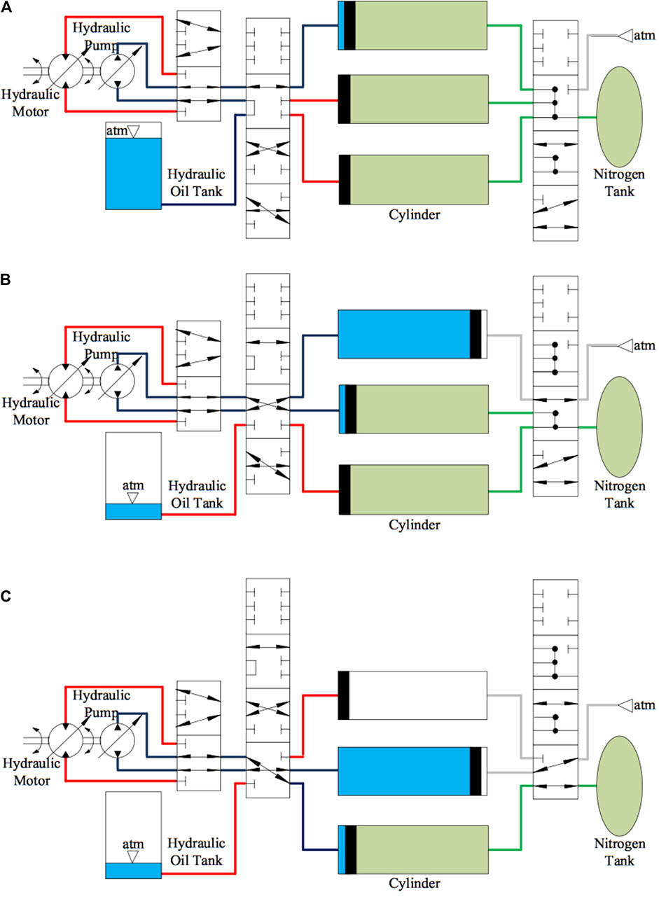
FIGURE 2. Charging stages (discharging stages) of IHESS: (A) Charging stage I (discharging stage III). (B) Charging stage II (discharging stage II). (C) Charging stage III (discharging stage I).
The working method of IHESS is as follows. In charging stage I, as shown in Figure 2A, the hydraulic pump drives the oil from the hydraulic oil tank to the first accumulator and compresses the remaining nitrogen into the nitrogen tank until the piston reaches the right end. In charging stage II, as shown in Figure 2B, the hydraulic pump drives the oil from the first accumulator to the second one and compresses nitrogen in the latter into the nitrogen tank until the piston reaches the right end, but air from the outside enters the first accumulator when the piston moves left. In charging stage III, as shown in Figure 2C, the hydraulic pump drives the oil from the second accumulator to the third one until all nitrogen is compressed into the nitrogen tank. The discharging process is the other way round.
The regular hydraulic ESS and the IHESS with the same energy storage capacity were compared in a study by Tong et al. (2018). Compared with the regular hydraulic ESS, the IHESS requires less amount of hydraulic oil and system installation space. Figure 3 presents the system and oil volume ratios of IHESS to regular hydraulic ESS. It shows that the IHESS with ten accumulators accounts for only 10% of oil and 64.78% of installation space of the regular ones, concerning a single-accumulator hydraulic ESS for storing the same amount of energy.
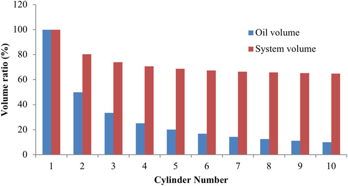
FIGURE 3. Volume ratio of IHESS to HESS (Tong, et al., 2018).
Since the IHESS requires less hydraulic oil and has a smaller volume and mass, it is suitable for hybrid power system integration and meets the demand of the potential energy recovery for HMTs. However, in the process of sizeable potential energy storage, the IHESS continually circulates a small amount of hydraulic oil to fulfill all nitrogen compression work. However, the compression heat and the heat generated in the hydraulic circuit are the same as in the counterpart single-accumulator hydraulic ESS. The oil temperature is likely to rise very high through the nitrogen–oil container heat conduction, resulting in the denaturation of oil and even damaging the hydraulic system. Meanwhile, carbon fiber composite nitrogen tanks and accumulators are widely used in vehicle-mounted ESS for their lightweight property. Since the honeycomb structure composed of carbon fiber and resin within impeding the inside heat transfer to air, and the carbon fiber has low radial thermal conductivity, it is difficult to decrease the system temperature. Therefore, it is imperative to propose a feasible thermal design.
In this section, the model of thermal resistance network, the model of heat conduction in plane walls and cylinders, and the model of heat convection on horizontal plates and vertical cylinders are introduced for the further establishment of the IHESS model.
This section studies the thermal resistance network for heat transfer analysis.
Since nitrogen, air, and hydraulic oil are present in the containers, the heat transfer between them is not only through thermal conduction but also through heat convection. They can be regarded as the thermal resistance network (Yunus, et al., 2015), in which the total heat flow
Here,
This section studies the heat conduction in plane walls and cylinders for thermal conduction analysis of pistons and top, bottom, and cylinder walls of accumulators and nitrogen tanks.
Based on the previous analytical work by F. P. Incropera (2007), the heat conduction resistance
Here,
Based on the previous analytical work by J. P. Holman (2002), the heat conduction resistance in cylinders is defined as follows:
Here,
This section studies the heat convection on horizontal plates for thermal convection analysis of nitrogen, ambient air, and hydraulic oil on pistons, and top and bottom surface of accumulators and nitrogen tanks.
By the Newton law of cooling (F. P. Incropera, 2007), the heat convection resistance
Here, the average convection heat transfer coefficient (Byron, 2004) is defined as follows:
Here,
For heat convection on horizontal plates, the characteristic length
Here,
Based on the previous experimental research by Lloyd et al. (1974), when it comes to a hot upper surface or a cold lower surface and the condition
holds, where
where
where
When the condition (Warner et al., 1968)
holds, the mean Nusselt number for horizontal plates can be defined as follows:
When it comes to a cold upper surface or a hot lower surface and the condition (Bayley, 1955)
holds, the mean Nusselt number for horizontal plates can be expressed as follows:
This section studies the heat convection on vertical cylinders for thermal convection analysis of nitrogen, ambient air, and hydraulic oil on cylinder surfaces of accumulators and nitrogen tanks.
For heat convection on vertical cylinders, the heat convection resistance and the mean convection heat transfer coefficient are the same as in Eqs 4, 5. Based on the previous experimental research by Warner et al. (1968) and analytical work by Bayley (1955), when the condition
holds, the mean Nusselt number for vertical cylinders can be expressed as follows:
When the condition (Lloyd et al., 1974)
holds, the mean Nusselt number for vertical cylinders can be calculated as follows:
In this section, the thermodynamic and heat transfer model of IHESS, which describes the thermodynamics of ambient air, nitrogen, and three changing parts of hydraulic oil, as well as various containers and heat conduction and convection between them, is established. It is necessary to analyze the heat generation and transfer process of IHESS for potential energy recovery.
This section studies the internal energy conversion of nitrogen by heat transfer and compression work.
Since all nitrogen in accumulators and nitrogen tanks is connected in the overall process as a working medium without mass transfer, it can be regarded as a closed gas system. By the first law of thermodynamics (J. P. Holman, 2002) and ignoring the friction in the gas circuit, the internal energy change in nitrogen
Here,
where
Thus, the internal energy of nitrogen is calculated as follows (Konami, 2017):
where
Therefore, the nitrogen temperature will be as follows:
From the ideal gas state equation (Munson and Young, 2013), the nitrogen pressure can be expressed as follows:
Here,
This section studies the internal energy conversion of hydraulic oil by heat transfer, oil exchange, and hydraulic heat generation.
Considering the incompressibility of the hydraulic oil (the compress work of the hydraulic oil
Here,
Taking the internal energy change
where
The internal energy change caused by the hydraulic oil flowing out of the accumulator is calculated as follows:
Here,
Therefore, the pressured oil temperature can be defined as follows (Parr, 2011):
The internal energy of the non-pressured hydraulic oil
where
The internal energy change caused by the hydraulic oil flowing in the accumulator can be calculated as follows:
Thus, the non-pressured oil temperature should be as follows (Parr, 2011):
In light of the internal energy change from heat generation in the hydraulic circuit (
where
Thus, the pipeline oil temperature can be calculated as follows (Parr, 2011):
This section studies the heat generation in the hydraulic pump and pipeline.
The efficiency loss of the hydraulic pump
Here,
There is viscous friction between the oil and pipeline, and there are abrupt changes in the cross section of the pipeline, both of which lead to the oil pressure loss
Here,
Considering that all the pressure loss of the pipeline oil is converted into the internal energy of it, the converting power
Therefore, the heat generation in the hydraulic circuit
This section studies the heat conduction and convection between the nitrogen or ambient air and hydraulic oil through the piston.
Since the cross-sectional area of the piston ring and the piston guide surface only accounts for a small proportion of the piston sidewall area, it can be seen as the adiabatic surface. So only the heat conduction between the gas–solid interface on the upper piston side and the solid–liquid interface on the lower piston side will be considered.
When the accumulator is in the state of compression or oil returning, the heat conduction through the piston can be regarded as a steady-state one-dimensional heat conduction problem in a plane wall. In this case, the temperature distribution between the piston’s upper and lower sides is linear. Therefore, the heat conduction resistance can be calculated as follows:
Here,
Meanwhile, the heat convection between the nitrogen, ambient air, hydraulic oil, and piston can be seen as the heat convection on horizontal plates, and the heat convection resistance can expressed as follows:
where the average convection heat transfer coefficient of the nitrogen, hydraulic oil, and atmospheric air on horizontal plates is expressed as follows:
where
The characteristic length can be expressed as follows:
Here,
For nitrogen and ambient air, when it comes to a cold upper surface and Eq. 13 holds, the mean Nusselt number of nitrogen and atmospheric air on cold upper horizontal plates can be expressed as follows:
where
When it comes to a hot upper surface and Eq. 7 holds, the mean Nusselt number of nitrogen and atmospheric air on hot upper horizontal plates can be expressed as follows:
When Eq. 11 holds, the mean Nusselt number can be expressed as follows:
For hydraulic oil on the cold lower surface, when Eq. 7 holds, the mean Nusselt number of the hydraulic oil on cold lower horizontal plates can be expressed as
where
When Eq. 11 holds, the mean Nusselt number can be expressed as follows:
When it comes to a hot lower surface and Eq. 13 holds, the mean Nusselt number can be expressed as follows:
This section studies the heat conduction and convection between the hydraulic oil and the accumulator bottom and sidewall.
When the accumulator is in the state of compression or oil returning, the heat conduction through the accumulator’s bottom can be regarded as a steady-state one-dimensional heat conduction problem in a plane wall. In this case, the temperature distribution between the accumulator bottom’s inner and outer sides is linear. Therefore, the heat conduction resistance is defined as follows:
Meanwhile, the heat convection between the hydraulic oil and the accumulator’s bottom can be seen as the heat convection on horizontal plates, and the heat convection resistance and convection heat transfer coefficient are given in Eqs 39, 40.
For hydraulic oil on the cold upper surface, when Eq. 13 holds, the mean Nusselt number can be expressed as follows:
When it comes to a hot upper surface and Eq. 7 holds, the mean Nusselt number can be calculated as follows:
When Eq. 11 holds, the mean Nusselt number should be as follows:
For heat conduction through the accumulator’s sidewall, which can be regarded as a steady-state one-dimensional heat conduction problem in a cylindrical wall, the temperature distribution between the accumulator sidewall’s inner and outer sides is a logarithmic curve. Therefore, the heat conduction resistance is as follows:
where
Meanwhile, the heat convection between the hydraulic oil and the accumulator sidewall can be seen as the heat convection on vertical cylinders, and the heat convection resistance is calculated as follows:
where the average convection heat transfer coefficient of the hydraulic oil on vertical cylinders is
where
When Eq. 15 holds, the mean Nusselt number can be expressed as follows:
where
When Eq. 17 holds, the mean Nusselt number can be expressed as follows:
This section studies the heat conduction and convection between the nitrogen and the accumulator and the nitrogen tank’s top, bottom, and sidewall.
When the accumulator is in the state of compression or nitrogen storing, the heat conduction through the accumulator’s top can be regarded as a steady-state one-dimensional heat conduction problem in a plane wall. The heat conduction resistance is the same as in Eq. 48.
Meanwhile, the heat convection between nitrogen and the accumulator’s top can be seen as the heat convection on horizontal plates, and the heat convection resistance and convection heat transfer coefficient are given in Eqs 39, 40.
For nitrogen on the cold down surface of accumulators, when Eq. 7 holds, the mean Nusselt number can be expressed as follows:
where
When Eq. 11 holds, the mean Nusselt number can be calculated as follows:
For heat conduction through the accumulator’s sidewall, the heat conduction resistance is expressed as follows:
where
For heat convection between nitrogen and the accumulator’s sidewall, the heat conduction resistance is defined as follows:
where the average convection heat transfer coefficient of nitrogen on vertical cylinders is as follows:
where
When Eq. 15 holds, the mean Nusselt number can be expressed as follows:
where
When Eq. 17 holds, the mean Nusselt number can be calculated as follows:
When the accumulator is in the state of nitrogen storing, it is filled with nitrogen. There is no oil left, and the piston and the accumulator’s bottom are in direct contact, so the two can be seen as an integral accumulator bottom. Therefore, the heat conduction through the integral accumulator bottom can be regarded as a steady-state one-dimensional heat conduction problem in a plane wall. The heat conduction resistance is expressed as follows:
While the heat convection between nitrogen and the integral accumulator bottom can be seen as the heat convection on horizontal plates, and the heat convection resistance and convection heat transfer coefficient are given in Eqs. 39, 40.
When Eq. 13 holds, the mean Nusselt number of nitrogen on the cold upper plates is expressed as follows:
where
For the nitrogen tank’s top, the heat conduction resistance can be defined as follows:
where
The heat convection is expressed as follows:
where the average convection heat transfer coefficient of nitrogen on horizontal plates and the characteristic length of the plate surface of the nitrogen tank are expressed as follows:
where
When Eq. 7 holds, the mean Nusselt number of nitrogen on the cold lower surface of the nitrogen tank can be expressed as follows:
where
When Eq. 11 holds, the mean Nusselt number can be calculated as follows:
For nitrogen tank’s sidewall, the heat conduction resistance can be defined as follows:
where
The heat convection is expressed as follows:
where the average convection heat transfer coefficient of nitrogen on vertical cylinders is
where
When Eq. 15 holds, the mean Nusselt number can be expressed as follows:
where
When Eq. 17 holds, the mean Nusselt number can be expressed as follows:
For the nitrogen tank’s bottom, the heat conduction and convection resistance and convection heat transfer coefficient are given in Eqs 66–68, and when Eq. 13 holds, the mean Nusselt number can be expressed as follows as follows:
where
This section studies the heat conduction and convection between ambient air and the accumulator’s top, bottom, and sidewall.
When the accumulator is in the state of oil returning or air storing, the heat conduction through the accumulator’s top can be regarded as a steady-state one-dimensional heat conduction problem in a plane wall. So the heat conduction resistance is the same as in Eq. 48.
Meanwhile, the heat convection between ambient air and the accumulator’s top can be seen as the heat convection on horizontal plates, and the heat convection resistance and convection heat transfer coefficient are given in Eqs 39, 40.
When Eq. 13 holds, the mean Nusselt number of atmospheric air on the hot lower plate of the accumulator can be expressed as follows:
where
For the accumulator sidewall, the heat conduction resistance is shown in Eq. 59, and the heat convection resistance is defined as follows:
where the average convection heat transfer coefficient of atmospheric air on vertical cylinders is as follows:
where
When Eq. 15 holds, the mean Nusselt number can be calculated as follows:
where
When Eq. 17 holds, the mean Nusselt number is expressed as follows:
When the accumulator is in the state of air storing, the heat conduction resistance for the integral accumulator bottom is given in Eq. 64. The heat convection between ambient air and the integral accumulator bottom can be seen as the heat convection on horizontal plates, and the heat convection resistance and convection heat transfer coefficient are given in Eqs 39, 40.
When Eq. 7 holds, the mean Nusselt number of atmospheric air on the hot upper plate of the accumulator can be calculated as follows:
where
When Eq. 11 holds, the mean Nusselt number can be expressed as follows:
Based on the above thermodynamic and heat transfer model, this section introduces the working cycle of mining trucks. It also analyzes the thermal characteristics of IHESS (parameters are given in Table 1) in the actual and simplified cycle with the cited dynamic model (Chun, et al., 2019) corresponding to the target vehicle, a 110 t HMT (specifications are given in Table 1), as well as the influence of the system structure and working condition parameters. Finally, a feasible energy-saving thermal design is put forward and its efficiency is analyzed.
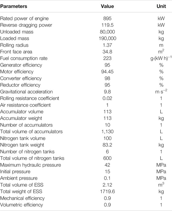
TABLE 1. Parameters of the vehicle and ESS.
This section introduces the working cycle of mining trucks for further simulation.
Figure 4 shows that the working cycle of mining trucks is as follows: Wait for loading, drive uphill with a full load, reach the unloading point and unload, and drive downhill without load. Table 2 shows that the total mileage is 10.861 km, and the maximum driving speed and road slope are 30 km h−1 and 3.9%, respectively. The actual working cycle (W. Yang, 2020) duration of the target HMT is 2,480 s, with the loading time being omitted. The uphill time with a full load is 1240 s. Figure 5 shows that the uphill slope is positive and the truckload is 110 t. The unloading time is 170 s, and in this period, the truck is stopped while the load decreases from 110 t to zero. The remaining 1070 s is for going downhill without load, and the downhill slope is negative, as shown in Figure 5. The corresponding simplified working cycle is set at the average recovery power of the actual one.
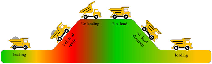
FIGURE 4. Transportation route of the mining truck (W. Yang, 2020).
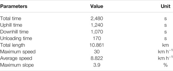
TABLE 2. Parameters of the actual working cycle.
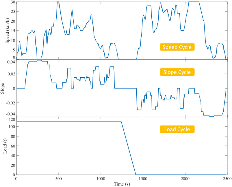
FIGURE 5. Actual working cycle of the target HMT.
The energy that is stored in the downhill process is output to the drivetrain in the power-following method during the uphill process. Thus, the output power of the engine is correspondingly decreased, which reduces the fuel consumption of the HMT. The thermal properties in the simulation are given in Table 3.
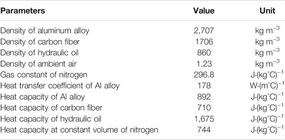
TABLE 3. Thermal properties.
This section studies the thermal performance in the actual cycle and simplified cycle and also discusses the physical analysis.
Figure 6 shows the temperature changes in nitrogen (Nitr), pressured hydraulic oil (Pres), non-pressured hydraulic oil (Nonp), pipeline oil (pipe), the No. 1 accumulator to No. 9 accumulator (ac1–ac9), and the nitrogen tanks (at) of IHESS in the actual working cycle. It can be seen that the nitrogen temperature rises with time followed by the nitrogen tank temperature, and there is a delay in the latter due to the heat convection resistance. The oil temperature also rises with time but apparently lower than nitrogen temperature. All figures are significantly affected by the actual recovery power.
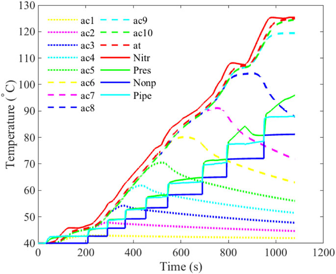
FIGURE 6. Thermal characteristics of IHESS in the actual cycle.
Since the thermal performance in the actual cycle only represents one specific working condition, whereas every working route of the HMT differs from one another, the simplified working cycle with the average recovery power of the actual one is put forward to provide a more inclusive sample. Besides, the fluctuation of the actual recovery power distorts the temperature change in the IHESS, while in the simplified cycle, it will present the original thermal influence from the oil-circulating circuit.
Figure 7 shows the temperature changes in nitrogen, hydraulic oil, and the containers of IHESS in the simplified working cycle. It is clear that the temperature of nitrogen rises approximately linearly with time, and the maximum is 125.12°C, as shown in Table 4. The pressured oil temperature rises and fluctuates with time and has the highest oil temperature of 93.13°C, and each fluctuation point corresponds with the accumulator-switching time. As we can see, the switching time becomes longer and longer after each oil circulation. It indicates that the former switched accumulators only operated for a short time at lower pressure and temperature, while the latter ones functioned at higher pressure and temperature for more time. The pipeline oil temperature is close to the pressured oil temperature but slightly lower. Since the pipeline oil does not have heat convection from containers, the escalating rise of its temperature is because the former hot pressured oil turned into non-pressured oil and drives into the pipeline after each switching point. The non-pressured oil also rises and fluctuates with time but has an opposite phase. After each switching point, its temperature is steady until the next point. This is because the large heat convection resistance of ambient air hinders the natural dissipation.
FIGURE 7. Thermal characteristics of IHESS in the simplified cycle.
TABLE 4. Highest temperatures and pressures in different cases.
Figure 7 shows that the nitrogen tank temperature is the highest one in the containers due to its full contact with hot nitrogen. Each accumulator’s temperature rises close to the nitrogen tank temperature until its switching point. After that point, the corresponding accumulator is connected to ambient air and slowly cools down.
This section carries out a comparative study on several cases with different parameters to analyze the factors causing overheating.
To analyze the influence of the system structure and working condition parameters on the thermal process, this article selects several cases with different parameters for simulation: first, the simplified working condition at 40°C ambient temperature with 3, 5, 15, and 20 accumulators, respectively, but the same total volume and second, the standard structure at 40°C ambient temperature with doubled working time and halved recovery power, and halved working time and doubled recovery power. Finally, these cases are compared with the standard one, which is the 10-accumulator system at 40°C ambient temperature in regular working time.
From the above discussions, we can see that nitrogen and pressured oil are the working mediums with the highest temperature in the system. Figure 8 and Figure 9 show their temperature changes in different cases. 3ac, 5ac, 10ac, 15ac, and 20ac represent the cases with 3, 5, 10, 15, and 20 accumulators in the system, respectively, but the same total volume. The highest temperatures and pressures in these cases are shown in Table 4. From that we can see that the systems with fewer accumulators but the same total volume have significantly lower temperatures and final pressures and the systems with more accumulators have the opposite outcomes. This difference is mainly because the oil volume of IHESS is determined by the number of accumulators, as shown in Figure 3, and the generated heat without heat dissipation is converted into the internal energy of the oil. Therefore, different total oil volumes result in different heat capacities of oil, which has a notable impact on the system’s thermal characteristics.
FIGURE 8. Nitrogen temperatures of IHESS in different cases.
FIGURE 9. Pressured oil temperatures of IHESS in different cases.
Figures 8, 9 also show that the nitrogen temperature and final pressure increase when the recovery power is doubled and the working time is halved (fast). However, its final pressured oil temperature decreased. It is due to the fact that there is lesser time for heat transfer. In contrast, the case with halved recovery power and doubled working time (slow) has the opposite outcomes.
Table 4 shows that under high ambient temperature (40°C), the highest oil temperature reached is 93.13°C. Such high temperature could cause oil denaturation and even damage the hydraulic system. From the above discussions, we can see that double or halve the recovery power is neither feasible for application on HMT nor effective for avoiding overheating of IHESS. Although adopting fewer accumulators significantly decreases the oil temperature by increasing the system heat capacity, we will lose the lightweight characteristic of IHESS.
Therefore, it is necessary to put forward a proper thermal design for dissipation to make the IHESS practicable.
This section puts forward an energy-saving coupled thermal design for the IHESS on HMTs and analyzes its performance.
During the energy storage process of HMTs when going downhill, the engine is in the reverse dragging condition. At this time, the fuel injection does not work, so there is no generated heat. However, its built-in cooling system generally operates in this state. At the same time, the IHESS generates heat, which needs to be cooled. During the uphill process, the engine is in the average power output condition. It generates heat, and the cooling system is still functioning. Meanwhile, nitrogen in the IHESS expands and produces cold potential, which needs to be heated for the full release of the stored energy. From the above discussions, we can see that in both uphill and downhill processes, the heat demand of the engine and IHESS is complementary. Therefore, a hydraulic oil cooling tank connected with the IHESS pipeline can be added next to the original cooling water tank of the engine. In this way, during the downhill process, the cooling air of the engine can cool down the oil in the pipeline, so as to the whole hydraulic oil, and further decrease the temperature of nitrogen through heat transfer.
The engine cooling system’s rated power is 30 kW, so the average cooling power of the modified IHESS should be less than this value. As the rated maximum temperature of the hydraulic oil for the target vehicle is 56°C, the minimum cooling power that achieved this requirement is obtained through simulations, and it is set to 6.68 kW in this paper.
Figure 10 shows the temperature changes in nitrogen, pressured hydraulic oil, non-pressured hydraulic oil, pipeline oil, the No. 1 accumulator to No. 9 accumulator, and the nitrogen tanks of standard structural IHESS with heat dissipation under the simplified working condition at 40°C ambient temperature. It can be seen that the temperature of nitrogen rises approximately linearly with time. The pressured oil temperature rises and fluctuates with time and has the highest oil temperature of 52.79 °C, and each fluctuation point corresponds with the accumulator-switching time, which becomes longer and longer after each oil circulation, just as it is in Figure 7. Due to the heat dissipation in the hydraulic circuit, the pipeline oil temperature is significantly lower than the pressured oil temperature. The non-pressured oil temperature also rises and fluctuates with time but has an opposite phase. After each switching point, its temperature is steady until the next point. We can also see that the nitrogen tank temperature is the highest one in the containers. Each accumulator’s temperature rises close to the nitrogen tank’s temperature until their switching point. After that point, the corresponding accumulator is connected to ambient air and slowly cools down. Compared with Figure 7, it can be seen that the temperatures of hydraulic oil and containers significantly decreased. Table 4 shows that the oil temperature is controlled below 56°C.
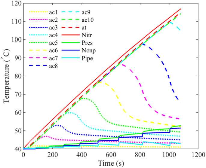
FIGURE 10. Thermal characteristics of IHESS in the dissipating cycle.
Figures 11A,B show the ratios of the heat source and heat transfer or storage of IHESS without heat dissipation in the simplified working cycle, respectively. It can be seen that the heat is mainly generated by nitrogen compression, which accounts for 81%. Most of the generated heat is converted into internal energy of nitrogen and hydraulic oil, accounting for about 90%. Figure 11C shows the ratio of heat storage or transfer of IHESS with heat dissipation at 40°C ambient temperature. From that we can see that, different from the case shown in Figure 11B, in which the heat generated by the system is mainly converted into the internal energy of oil and nitrogen, 28% of the generated heat in the system is released through the cooling system after heat dissipation. By this, the system temperature is effectively decreased.
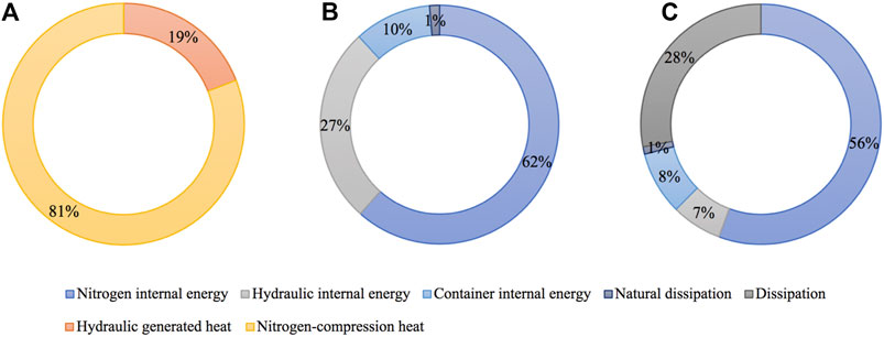
FIGURE 11. Ratios of the heat source and heat transfer or storage of IHESS: (A) Heat source. (B) Heat storage. (C) Dissipated heat storage.
To sum up, for IHESS with 10 accumulators without heat dissipation at 40°C ambient temperature, the oil temperature reaches 93.13°C. About 90% of the generated heat is converted into the internal energy of nitrogen and oil. On this basis, by adopting the energy-saving passive cooling system with a cooling power of 6.68 kW, the highest temperature of the oil drops to 52.79°C and 28% of the generated heat is released through the cooling system.
In this article, the thermodynamic and heat transfer model of the IHESS is proposed. Based on the dynamic model of mining trucks, thermal characteristics of IHESSs with different parameters under the actual and simplified working conditions are studied and the factors causing overheating are analyzed. Finally, a feasible energy-saving thermal design is proposed and its efficiency is analyzed. The main conclusions are as follows: More accumulators and higher recovery power lead to higher system temperature and vice versa. Under the standard simplified working condition at 40°C ambient temperature, the highest oil temperature reached is 93.13°C. About 90% of the generated heat is converted into the internal energy of nitrogen and oil. On this basis, by adopting the energy-saving passive cooling system with a cooling power of 6.68 kW, the highest temperature of the oil drops to 52.79°C and 28% of the generated heat is released through the cooling system. IHESS is a novel compact hydraulic ESS with only 10% of oil and 64.78% of installation space of the regular ones. The above conclusions put forward an effective solution to the overheating problem of IHESS and provide a basis for the thermal process analysis of it. As a result, it paves the way for the practical application of IHESS on hybrid mining trucks.
The original contributions presented in the study are included in the article/Supplementary Material; further inquiries can be directed to the corresponding author.
Conceptualization, TY and FM; methodology, JH and CJ; software, TY and JH; validation, CJ and TY; formal analysis, JH; resources, CJ; writing—original draft preparation, TY; writing—review and editing, JH, TY, and FM; supervision, FM and YL; and funding acquisition, FM and YL. All authors have read and agreed to the published version of the manuscript.
This research was funded by Ministry of Science and Technology of the People’s Republic of China, grant number SQ2016YFSF060248, and Shunde Graduate School of University of Science and Technology Beijing, grant number BK19CE001.
The authors declare that the research was conducted in the absence of any commercial or financial relationships that could be construed as a potential conflict of interest.
All claims expressed in this article are solely those of the authors and do not necessarily represent those of their affiliated organizations, or those of the publisher, the editors and the reviewers. Any product that may be evaluated in this article, or claim that may be made by its manufacturer, is not guaranteed or endorsed by the publisher.
The author, therefore, acknowledge and thank Ministry of Science and Technology of the People’s Republic of China and Shunde Graduate School of University of Science and Technology Beijing, for their technical and financial support.
Aziz, A. S., Naim tajuddin, M. F., and Adzman, M. R. (2018). Feasibility Analysis of PV/Wind/Battery Hybrid Power Generation: A Case Study. Int. J. Renew. Energ. Res. 8 (2), 661–671.
Bayley, F. J. (1955). An Analysis of Turbulent Free-Convection Heat-Transfer. Proc. Inst. Mech. Eng. 169 (20), 361–370. doi:10.1243/PIME_PROC_1955_169_049_02
Chun, J., Yi, T., Shen, Y., Khajepour, A., and Meng, Q. (2019). Comparative Study on the Economy of Hybrid Mining Trucks for Open-Pit Mining. IET Intell. Transport Syst. 13, 201–208. doi:10.1049/iet-its.2018.5085
Dagdougui, Y., Ouammi, A., and Benchrifa, R. (2020). High Level Controller-Based Energy Management for a Smart Building Integrated Microgrid with Electric Vehicle. Front. Energ. Res. 8, 535535. doi:10.3389/fenrg.2020.535535
Ding, Y., Wang, T., Dong, D., and Zhang, Y. (2020). Using Biochar and Coal as the Electrode Material for Supercapacitor Applications. Front. Energ. Res. 7, 159. doi:10.3389/fenrg.2019.00159
Dransfield, P. (1981). Hydraulic Control Systems -- Design and Analysis of Their Dynamics. Berlin: Springer-Verlag.
DunnKamath, B. H., Kamath, H., and Tarascon, J.-M. (2011). Electrical Energy Storage for the Grid: a Battery of Choices. Science 334 (6058), 928–935. doi:10.1126/science.1212741
Ehsan, E., and Meech, J. A. (2013). Hybrid Electric Haulage Trucks for Open Pit Mining. IFAC Proc. Volumes 46 (16), 104–109. doi:10.3182/20130825-4-US-2038.00042
Kantharaj, B., Garvey, S., and Pimm, A. (2015). Thermodynamic Analysis of a Hybrid Energy Storage System Based on Compressed Air and Liquid Air. Sustainable Energ. Tech. assessments 11, 159–164. doi:10.1016/j.seta.2014.11.002
Kim, Y. M., and Favrat, D. (2010). Energy and Exergy Analysis of a Micro-compressed Air Energy Storage and Air Cycle Heating and Cooling System. Energy 35, 213–220. doi:10.1016/j.energy.2009.09.011
Koellner, W. G., Brown, G. M., Rodriguez, J., Pontt, J., Cortes, P., and Miranda, H. (2004). Recent Advances in Mining Haul Trucks. IEEE Trans. Ind. Electron. 51 (2), 321–329. doi:10.1109/TIE.2004.825263
Koseoglou, M., Tsioumas, E., Jabbour, N., and Mademlis, C. (2020). Highly Effective Cell Equalization in a Lithium-Ion Battery Management System. IEEE Trans. Power Electron. 35 (2), 2088–2099. doi:10.1109/TPEL.2019.2920728
Kwon, T. S., Lee, S. W., Sul, S. K., Park, C. G., Kim, N. I., Kang, B. I., et al. (2010). Power Control Algorithm for Hybrid Excavator with Supercapacitor. IEEE Trans. Ind. Applicat. 46 (4), 1447–1455. doi:10.1109/TIA.2010.2049815
Lajunen, A. (2015). Energy Efficiency of Conventional, Hybrid Electric, and Fuel Cell Hybrid Powertrains in Heavy Machinery. SAE Paper 01, 2829. doi:10.4271/2015-01-2829
Li, P. Y., Loth, E., Simon, T. W., Vandeven, J. D., and Crane, S. E. (2011). “Compressed Air Energy Storage for Offshore Wind Turbines,” in International Fluid Power Exhibition (IFPE).
Lloyd, J. R., and Moran, W. R. (1974). Natural Convection Adjacent to Horizontal Surfaces of Various Planforms. J. Heat Transfer 96, 443–447. doi:10.1115/1.3450224
Munson, B. R., and Young, D. F. (2013). Fundamentals of Fluid Mechanics. Ames, Iowa, USA: John Wiley & Sons.
Newman, A. M., Rubio, E., Caro, R., Weintraub, A., and Eurek, K. (2010). A Review of Operations Research in Mine Planning. Interfaces 40 (3), 222–245. doi:10.1287/inte.1090.0492
Orlande, H. R. B. (2011). Thermal Measurements and Inverse Techniques. Boca Raton: CRC Press, 776. doi:10.1201/b10918
Parr, E. A. (2011). Hydraulics and Pneumatics: A Technician's and Engineer's Guide. Amsterdam: Elsevier/Butterworth-Heinemann.
Patra, K., C. (2011). Engineering Fluid Mechanics and Hydraulic Machines. Oxford: Alpha Science International.
Richter, T., Slezak, L., Johnson, C., Young, H., and Funcannon, D. (2007). “Advanced Hybrid Propulsion and Energy Management System for High Efficiency, off Highway, 240 Ton Class, Diesel Electric Haul Trucks,” in Annual Progress Report for Heavy Vehicle Systems Optimization Program, Washington, D.C. doi:10.2172/1092149
Schulthoff, M., Rudnick, I., Bose, A., and Gençer, E. (2021). Role of Hydrogen in a Low-Carbon Electric Power System: A Case Study. Front. Energ. Res. 8. doi:10.3389/fenrg.2020.585461
Ta, C. H., Kresta, J. V., Forbes, J. F., and Marquez, H. J. (2005). A Stochastic Optimization Approach to Mine Truck Allocation. Int. J. Surf. Mining, Reclamation Environ. 19 (3), 162–175. doi:10.1080/13895260500128914
Taliotis, C., Fylaktos, N., Partasides, G., Gardumi, F., Sridharan, V., Karmellos, M., et al. (2020). The Effect of Electric Vehicle Deployment on Renewable Electricity Generation in an Isolated Grid System: The Case Study of Cyprus. Front. Energ. Res. 8, 205. doi:10.3389/fenrg.2020.00205
Vasel-Be-Hagh, A., Carriveau, R., and Ting, D. S.-K. (2014). Underwater Compressed Air Energy Storage Improved through Vortex Hydro Energy. Sustainable Energ. Tech. Assessments 7, 1–5. doi:10.1016/j.seta.2014.02.001
Warner, C. Y., and Arpaci, V. S. (1968). An Experimental Investigation of Turbulent Natural Convection in Air at Low Pressure along a Vertical Heated Flat Plate. Int. J. Heat Mass Transfer 11, 397–406. doi:10.1016/0017-9310(68)90084-7
Xiao, X., Chen, Z., Wang, C., and Nie, P.-y. (2020). Effect of an Electric Vehicle Promotion Policy on China's Islands: A Case Study of Hainan Island. Front. Energ. Res. 8, 132. doi:10.3389/fenrg.2020.00132
Xu, P-P., Ma, F., Tengfei, C., Yi, T., and Pan, Y. (2015). The Frequency Feature Extraction of the Signal in Oscillation Cavity of a Self-Resonating Jet Nozzle Based on Improved HHT Method. Chin. J. Eng. 12 (1), 99–105. doi:10.13374/j.issn2095-9389.2015.s2.016
Xue, P., Xiang, Y., Gou, J., Xu, W., Sun, W., Jiang, Z., et al. (2021). Impact of Large-Scale Mobile Electric Vehicle Charging in Smart Grids: A Reliability Perspective. Front. Energ. Res. 9, 688034. doi:10.3389/fenrg.2021.688034
Yang, W. (2020). Investigation of Control Strategy of an Innovational Hybrid Electric Transmission System for Off-Road Trucks. Beijing: Beijing University of science and technology. [doctoral dissertation].
Yi, T., Ma, F., Jin, C., and Huang, Y. (2018). A Novel Coupled Hydro-Pneumatic Energy Storage System for Hybrid Mining Trucks. Energy 143, 704–718. doi:10.1016/j.energy.2017.10.131
Yunus, A., and Afshin, J. G. (2015). Heat and Mass Transfer: Fundamentals and Applications. New York: McGraw-Hill.
Zhao, Y., Liu, P., Wang, Z., Zhang, L., and Hong, J. (2017). Fault and Defect Diagnosis of Battery for Electric Vehicles Based on Big Data Analysis Methods. Appl. Energ. 207, 354–362. doi:10.1016/j.apenergy.2017.05.139
A inner cross-sectional area
ac hydraulic accumulator
Al Aluminum
at nitrogen tank
atm atmospheric air
b perimeter
btm bottom side
c heat capacity at constant volume
CA nitrogen
cir hydraulic circuit
cold cold surface
cond heat conduction
conv heat convection
d diameter
down down surface
G Grashof number
g gravitational acceleration
gen heat generation
h convection heat transfer coefficient
hot hot surface
Hy hydraulic oil
in the hydraulic oil flow into an accumulator
inner inner diameter
k heat transfer coefficient
L length
l hydraulic oil height in the accumulator
loss efficiency loss
m mass
me mechanical
N Nusselt number
out the hydraulic oil flow out of an accumulator
outer outer diameter
P Prandtl number
p pressure
pump hydraulic pump
Q heat flow
q hydraulic oil flow
R thermal resistance
r gas constant
side cylinder wall
T temperature
t time
top top side
U internal energy
up upper surface
V volume
v volumetric
W power
Z characteristic length
α thermal diffusivity
β volume expansion coefficient
δ thickness
η efficiency
λ friction coefficient
ν kinematic viscosity
ξ local resistance coefficient
ρ density
1 pressured hydraulic oil
2 non-pressured hydraulic oil
ESS energy storage system
HMT hybrid mining truck
IHESS improved hydraulic energy storage system
Keywords: thermal characteristics, hybrid mining truck, energy storage system (EES), hydraulic oil circulation, heat transfer model
Citation: Yi T, Ma F, Jin C, Hong J and Liu Y (2021) Investigation on Thermal Characteristics of the Oil-Circulating Hydraulic Energy Storage System for Hybrid Mining Trucks. Front. Energy Res. 9:733919. doi: 10.3389/fenrg.2021.733919
Received: 30 June 2021; Accepted: 10 August 2021;
Published: 01 October 2021.
Edited by:
Enhua Wang, Beijing Institute of Technology, ChinaReviewed by:
Yanxin Hu, Guangdong University of Technology, ChinaCopyright © 2021 Yi, Ma, Jin, Hong and Liu. This is an open-access article distributed under the terms of the Creative Commons Attribution License (CC BY). The use, distribution or reproduction in other forums is permitted, provided the original author(s) and the copyright owner(s) are credited and that the original publication in this journal is cited, in accordance with accepted academic practice. No use, distribution or reproduction is permitted which does not comply with these terms.
*Correspondence: Fei Ma, eWVrZUB1c3RiLmVkdS5jbg==
Disclaimer: All claims expressed in this article are solely those of the authors and do not necessarily represent those of their affiliated organizations, or those of the publisher, the editors and the reviewers. Any product that may be evaluated in this article or claim that may be made by its manufacturer is not guaranteed or endorsed by the publisher.
Research integrity at Frontiers
Learn more about the work of our research integrity team to safeguard the quality of each article we publish.