 He Jiang
 Mofan Wei1,2
- 1School of Renewable Energy, Shenyang Institute of Engineering, Shenyang, China
- 2Key Laboratory of Regional Multi-energy System Integration and Control of Liaoning Province, Shenyang, China
Sliding mode control can restrain the perturbations generated from the intermittence of the renewable energy generation and the randomness of local loads when microgrids are operating in islanded mode. However, the microgrid consists of several subsystems and the interactions among them will cause the chattering problems under the overall sliding mode control. In this paper, the chattering restraint issues for voltage control of the islanded microgrid with a ring topology structure are investigated based on the decentralized adaptive sliding mode control strategies. Firstly, we construct a tracking error system with interconnections considering the power transmission among subsystems and nominal values of system states. Secondly, we design linear matrix inequalities (LMIs) according to the
Introduction
Recently, there are abundant distributed generating devices permeating in the modern electric power systems for achieving the environment protection and the effective and flexible control of grids. In order to ensure the extensiveness and security of the power supply, microgrids have been the main form to transmit electricity to local loads for remote regions, which can operate in islanded mode or grid-connected mode (Mahmoud et al., 2014). Actually, an AC islanded microgrid consisting of distributed generation units (DGus) and energy storage devices can supply power to local loads steadily in low voltage magnitude (Kabalan et al., 2017). Because the microgrid contains numerous power electronic facilities, such as voltage source converters (VSC) et al., it is lack of immense inertia provided by rotating devices comparing with conventional grids (Zou et al., 2019). Furthermore, the renewable generation devices are usually affected by weather conditions and the power generated from them is usually intermittent and uncertain, so it is more complicated to realize the stable control of the multi-area microgrid voltage when it is in islanded mode (Zhou et al., 2021). At present, there are different control strategies to solve the voltage control problems of multi-area microgrids and optimize the control performance in islanded mode in order to improve the reliability and effectiveness of the power supply (Divshali et al., 2012; Sahoo et al., 2018).
The conventional control methods for multi-area microgrids operating in islanded mode demonstrate several disadvantages. The close-loop proportional-integral-derivative (PID) voltage control strategy can not estimate the errors between state variables and the nominal sinusoidal voltages accurately. Additionally, this control strategy presents bad control performance for restraining the inner parameter perturbations, such as frequency fluctuations (Vandoorn et al., 2013; Chen et al., 2015; Sefa et al., 2015). Zeb et al. (2019) combined the PID control method with fuzzy principles and designed the proportional resonant harmonic compensator as a current controller. Moreover, a phase lock loop (PLL) was designed to promote the speed of the system dynamic response. A comparison between fuzzy sliding mode control (FSMC) and fuzzy PID control illustrated that the dynamic response speed was lower and the tracking error performance was less precise via the fuzzy PID method. Considering that microgrids are sensitive about the system parameter variations, so the droop control technology is proposed to improve the robustness of microgrids via simulating the droop relationships among different electrical parameters (Avelar et al., 2012; Beerten and Belmans, 2013; Eren et al., 2015; Wang et al., 2019; Wang et al., 2021). Mi et al. (2019) modified traditional linear droop control strategies and utilized nonlinear droop relationships to describe the interactions between reactive power and voltages. The T-S fuzzy theory was applied to approximate the nonlinear model accurately and coordinate power among each DGu. Nevertheless, there were also errors between stable values and nominal values of voltages. Recently, sliding mode control (SMC) strategies are extensively applied in the stability control of microgrids for the superior asymptotic stability and robustness against parameter uncertainties (Hu et al., 2010; Karimi et al., 2010; Liu et al., 2017). An integration model of microgrids with complex meshed topology structures and several DGus was constructed to achieve the power sharing and voltage robust control (Cucuzzella et al., 2017; Wang et al., 2020). But the integration model could not represent actual interaction effects in different subsystems and the chattering was serious. Mi et al. (2020) proposed an adaptive sliding mode control strategy based on the sliding mode observer for wind-diesel power systems. The microgrid bus voltage showed remarkable stability via regulating the reactive power in terms of this method. Contrarily, the disturbance observer and adaptive algorithm brought in numerous parameters and promoted the complexity of the control system. To figure out the problem of harmonic disturbance in microgrids, Esparza et al. (2017) proposed a comprehensive control strategy to restrain the harmonic currents generated from DGus in AC microgrids. As shown in the simulation results, this strategy could cause the chattering phenomenon inherently.
Motivated by the aforementioned discussions, for the multi-area microgrid with a ring topology, the decentralized voltage control model will represent more appropriate relationships among the parameters in each local subsystem comparing with the integrated one. In addition, the adaptive sliding mode control (ASMC) strategy, which will be designed according to
The main contributions of this paper can be summarized as follows:
1) The established multi-area microgrid model can depict the interactions among subsystems appropriately;
2) The reliability of solutions and the attenuation performance of external disturbances can be ensured based on the linear matrix inequalities (LMIs);
3) The proposed decentralized ASMC can restrain the chattering of the microgrid.
The rest of research includes four sections. Section Dynamical Models of Multi-Area Interconnected Microgrids constructs state functions with interconnections representing the topology structure of microgrid systems and defines tracking error models based on the nominal values of the state variables. Section Proposed Decentralized Adaptive Sliding Mode Voltage Controller introduces the designed decentralized voltage controllers in terms of the proposed ASMC theory. Section Simulation Results provides the simulation results and Section Conclusion illustrates the conclusion.
Dynamical Models of Multi-Area Interconnected Microgrids
In order to explain the power transmission among the multi-area microgrid, the electrical three-phase diagram of the ring topology system composed four DGus is shown in Figure 1. The researched microgrid consists of local loads, power transmission lines and DGus. Because of various energy storage components in renewable generation systems, the DGus could be represented as DC voltage sources. The DGus connect with the points of common coupling (PCC) via VSCs and filters and provide power to local loads. PCCs can also link one of areas of the microgrids to another and connect microgrids with main grids.
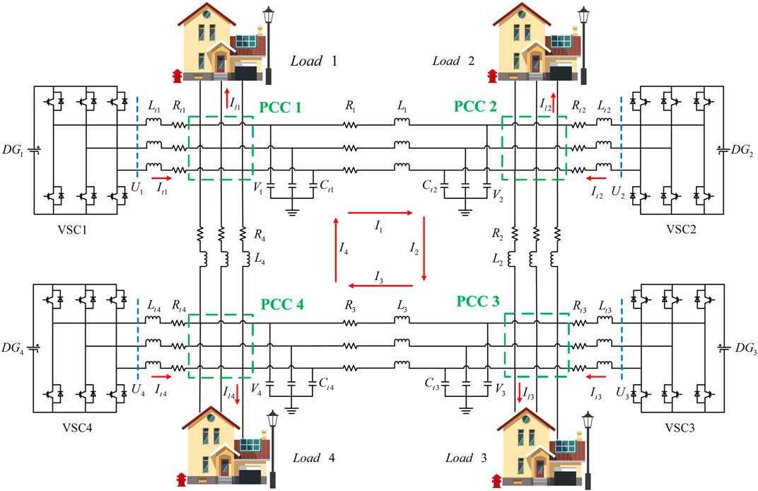
FIGURE 1. The structure of interconnected microgrids with ring topology.
Considering the ring topology structure of the microgrid and the power transmission orientations among different areas, the voltage control model of subsystem
where
where
where
Assume that the nominal vector of the state vector in subsystem
In view of (9), the corresponding error dynamic model in subsystem
where
For the later proof proceedings, we introduce the following lemmas, which can be needed to ensure the asymptotic stability of the system.
Lemma 1: (Mnasri and Gasmi, 2011) Consider the following unforced system:
This system is regarded as quadratically stable and satisfies the
Lemma 2: (Mnasri and Gasmi, 2011) Let
Lemma 3: (Mnasri and Gasmi, 2011) Consider a partitioned symmetric matrix
where
Proposed Decentralized Adaptive Sliding Mode Voltage Controller
The adaptive algorithm can optimize the parameters in controller and the decentralized strategy can improve the control performance. Design proceedings of sliding surface need to consider the stabilizing, tracking and restraining performance of the system. The sliding mode control law usually contains two parts, the switching control law and the equivalent control law. The former one can force the system state to approximate to the sliding surface when it deviates from the surface and the latter one can ensure the system state to keep on the sliding surface when it reaches on the surface.
In order to design decentralized adaptive sliding mode voltage control laws for error dynamic model (11), the following assumptions are introduced.
Assumption 1: All the parameter uncertainty matrices caused by frequency fluctuations are viewed as bounded. That means
Assumption 2: For each subsystem
For improving the dynamic response performance, we define the following integral sliding mode surface as
where
When the state trajectory of the tracking error system arrive and keep on the sliding mode surface, it would satisfy the following equation.
Based on Equation 17, equivalent control law can be represented as
Substituting Equation (18) into (11), the sliding mode dynamic equation can further be expressed as
where
Theorem 1: Assume that the tracking error system (19) satisfies Assumption 1 and Assumption 2. If there exists a feasible solution
where
is asymptotic stable.
Proof: Select the following Lyapunov function for tracking error system (19).
Based on an
If
Consider
where
Define
where
Theorem 2:Design the following controller (28) for closed-loop system (11) in terms of the feasible solution obtained via (20) and the system dynamic is asymptotic stable based on
where
where
Proof: Let us consider the following Lyapunov function:
where
Obviously, the derivative of the Lyapunov function
Simulation Results
In this section, the proposed decentralized ASMC strategy is applied in the voltage control of microgrid with ring topology. The microgrid on study contains four DGus (

TABLE 1. Electrical parameters of the microgrid.

TABLE 2. Electrical parameters of the interconnecting lines.
The intermittence of the renewable generation and the uncertaintiy of the local load in microgrid will influence the power sharing among subsystems and cause frequency fluctuation indirectly. In this case, we consider the frequency fluctuation
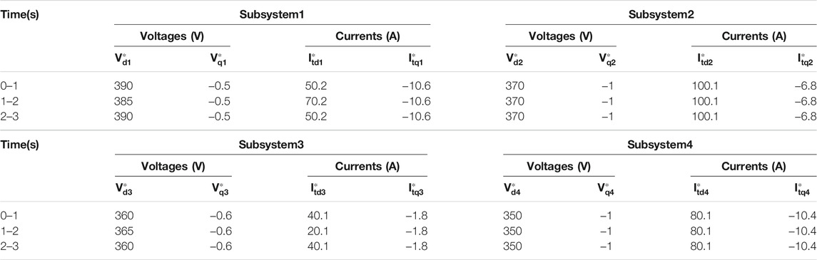
TABLE 3. The reference values of state variables in each subsystem.
In the following simulation procedures, we analysis the simulation results and verify the validity of the proposed decentralized ASMC strategies under frequency disturbances and local load uncertainties. Because the system uncertainties are bounded, we can get
In order to restrain the mismatched uncertainties and external disturbances, for tracking error system (11), the adaptive parameters are selected as
The voltages and currents of the islanded microgrid demonstrate superior robustness and tracking error performance under the proposed decentralized ASMC strategy. The time evolutions of the dq-components of the currents generated from each DGu are depicted in Figure 2 and Figure 3 respectively in the case of load currents mutation.

FIGURE 2. Time evolution of the d-component of currents generated from DGus.
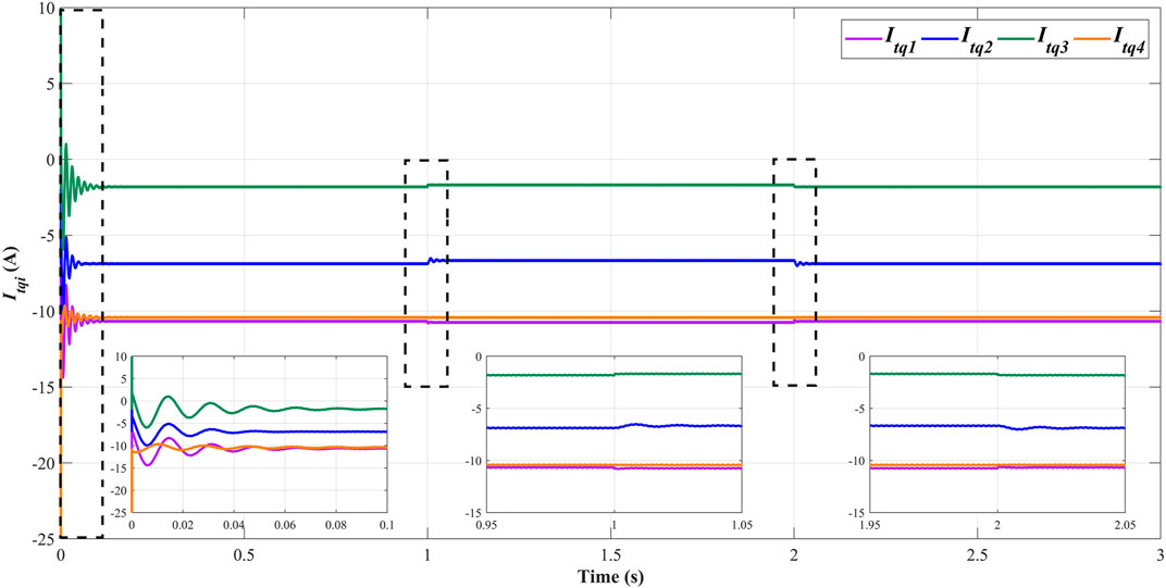
FIGURE 3. Time evolution of the q-component of currents generated from DGus.
The time evolutions of the dq-components of the PCC voltages of each subsystem are shown in Figure 4 and Figure 5. Considering the load current variations in the interconnected microgrid system,
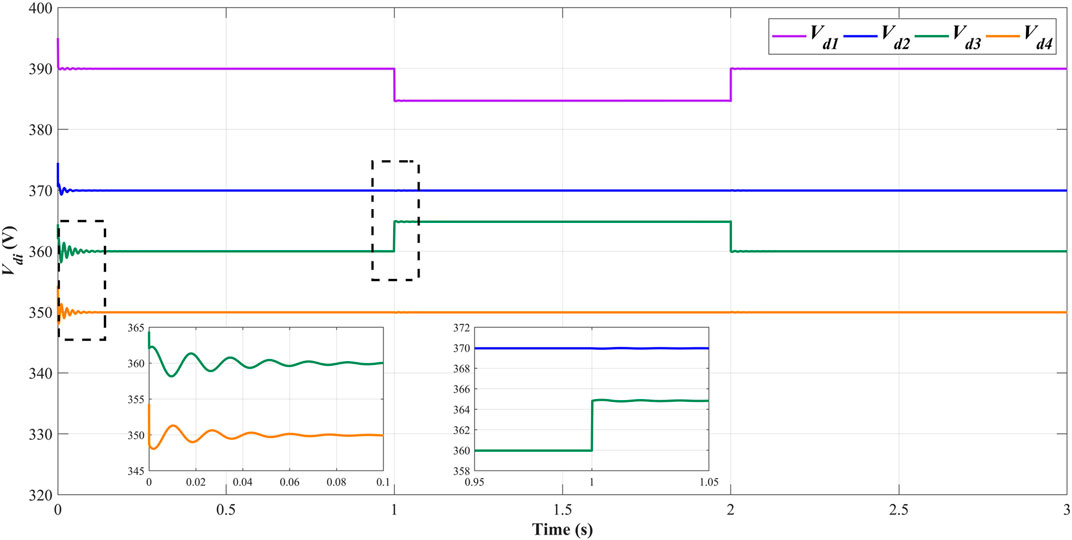
FIGURE 4. Time evolution of the d-component of voltages of PCCs.
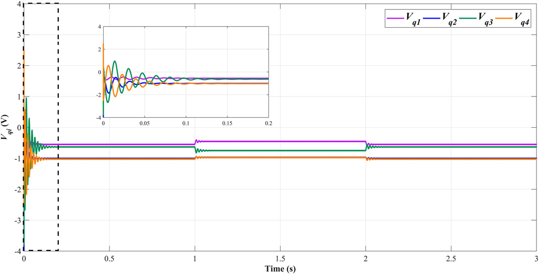
FIGURE 5. Time evolution of the q-component of voltages of PCCs.
The time evolutions of the dq-components of the currents of interconnecting lines are represented in Figure 6 and Figure 7. Under the influence of mutations of load currents and PCC voltages, the currents of interconnecting lines are only influenced by the voltages of PCCs and do not deviate from the reference values appreciably, which illustrates the remarkable robustness of proposed ASMC strategy against the external disturbances and mismatched uncertainties. That also means the changes of local load currents will not influence the stability of the general microgrid. Notably, the current orientation of line four is opposite compared with the currents of other lines because the voltage of PCC four is lower than that of PCC1.

FIGURE 6. Time evolution of the d-component of currents of interconnecting lines.
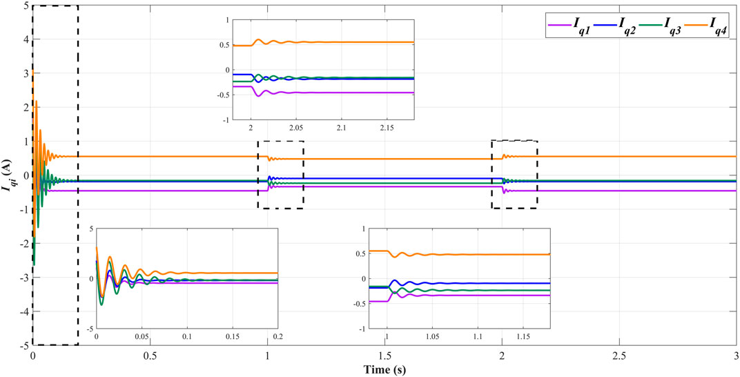
FIGURE 7. Time evolution of the q-component of currents of interconnecting lines.
Figure 8 and Figure 9 depict the three-phase waveforms of currents generated from DGus. Figure 10 and Figure 11 depict the three-phase waveforms of voltages of PCCs in subsystem one and subsystem 3. In islanded mode, the decentralized controllers are mainly designed to standardize the voltage and current waves and improve the power quality of AC microgrid. In Figure 8 and Figure 9, the amplitude of three-phase wave of the current generated from DGu1 increases 20 A and that of DGu3 decreases 20 A at
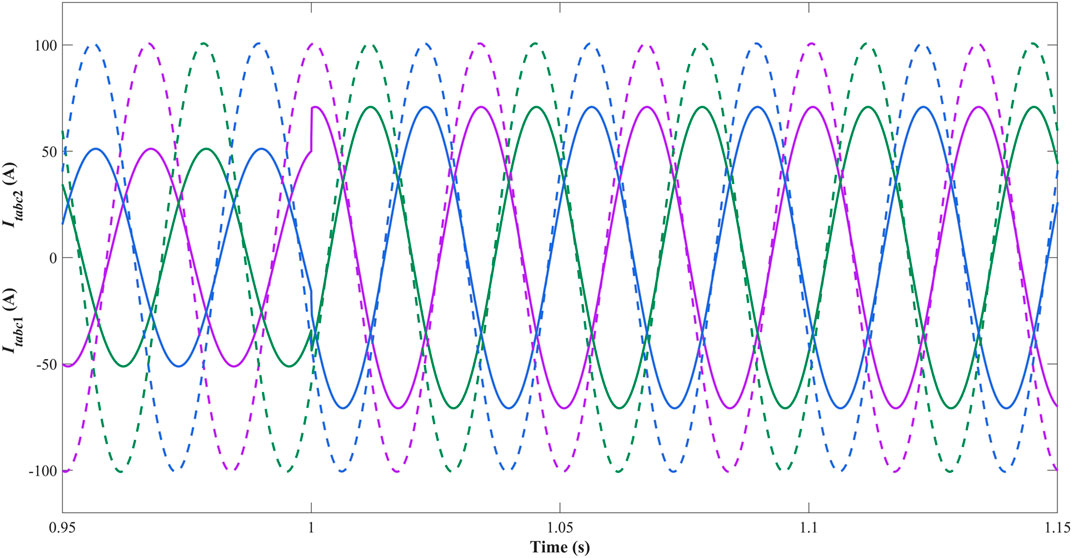
FIGURE 8. Three-phase waveforms of currents generated from DGu1 and DGu2.
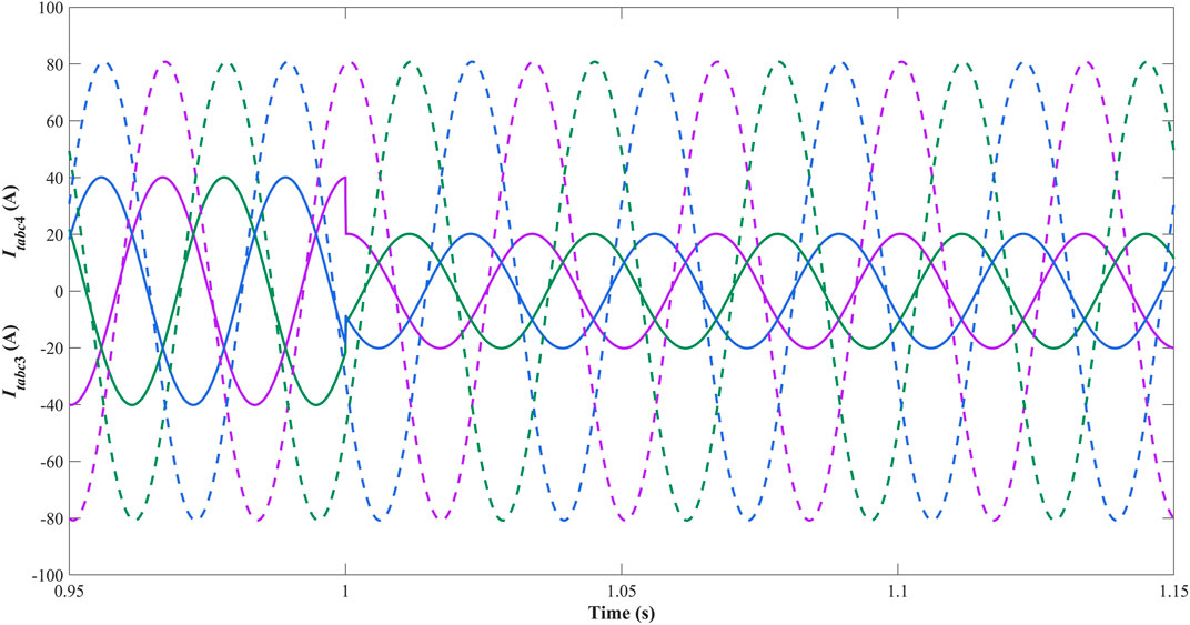
FIGURE 9. Three-phase waveforms of currents generated from DGu3 and DGu4.
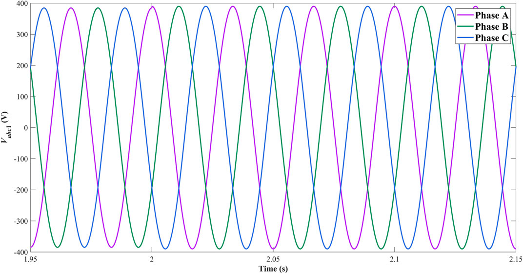
FIGURE 10. Three-phase waveforms of PCC1 voltage.
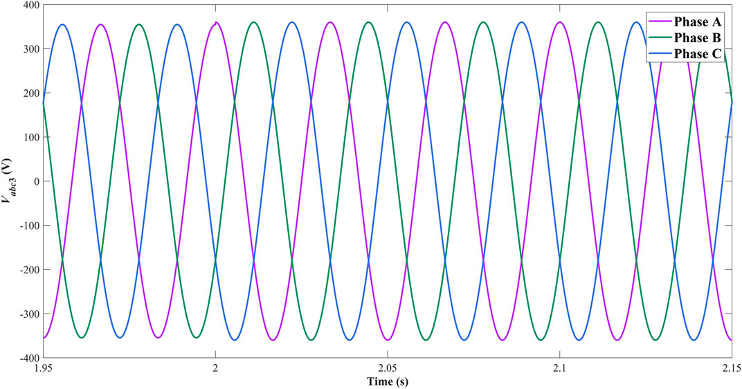
FIGURE 11. Three-phase waveforms of PCC3 voltage.
Conclusion
In this paper, the chattering restraint issues for voltage control of the islanded microgrid with a ring topology structure have been solved via decentralized adaptive sliding mode control strategies. The constructed tracking error system with interconnections has depicted the interaction among each subsystem appropriately. The control matrices in sliding mode surfaces have been obtained via solving the LMIs, which combine the
Data Availability Statement
The raw data supporting the conclusions of this article will be made available by the authors, without undue reservation.
Author Contributions
HJ was responsible for the main idea and writing work of this paper. YZ and JH were responsible for the mathematical derivation. MW was responsible for the simulation part.
Funding
Doctoral Scientific Research Foundation of Liaoning Province (2020-BS-181). Liaoning Revitalization Talents Program (XLYC1907138). Natural Science Foundation of Liaoning Province (2019-MS-239). Key R&D Program of Liaoning Province (2020JH2/10300101).
Conflict of Interest
The authors declare that the research was conducted in the absence of any commercial or financial relationships that could be construed as a potential conflict of interest.
Publisher’s Note
All claims expressed in this article are solely those of the authors and do not necessarily represent those of their affiliated organizations, or those of the publisher, the editors and the reviewers. Any product that may be evaluated in this article, or claim that may be made by its manufacturer, is not guaranteed or endorsed by the publisher.
References
Avelar, H. J., Parreira, W. A., Vieira, J. B., de Freitas, L. C. G., and Coelho, E. A. A. (2012). A State Equation Model of a Single-phase Grid-Connected Inverter Using a Droop Control Scheme with Extra Phase Shift Control Action. IEEE Trans. Ind. Electron. 59, 1527–1537. doi:10.1109/TIE.2011.2163372
Beerten, J., and Belmans, R. (2013). Analysis of Power Sharing and Voltage Deviations in Droop-Controlled DC Grids. IEEE Trans. Power Syst. 28, 4588–4597. doi:10.1109/TPWRS.2013.2272494
Chen, Z., Luo, A., Wang, H., Chen, Y., Li, M., and Huang, Y. (2015). Adaptive Sliding-Mode Voltage Control for Inverter Operating in Islanded Mode in Microgrid. Int. J. Electr. Power Energ. Syst. 66, 133–143. doi:10.1016/j.ijepes.2014.10.054
Cucuzzella, M., Incremona, G. P., and Ferrara, A. (2017). Decentralized Sliding Mode Control of Islanded AC Microgrids with Arbitrary Topology. IEEE Trans. Ind. Electron. 64, 6706–6713. doi:10.1109/TIE.2017.2694346
Divshali, P. H., Alimardani, A., Hosseinian, S. H., and Abedi, M. (2012). Decentralized Cooperative Control Strategy of Microsources for Stabilizing Autonomous VSC-Based Microgrids. IEEE Trans. Power Syst. 27, 1949–1959. doi:10.1109/TPWRS.2012.2188914
Eren, S., Pahlevani, M., Bakhshai, A., and Jain, P. (2015). An Adaptive Droop DC-Bus Voltage Controller for a Grid-Connected Voltage Source Inverter with LCL Filter. IEEE Trans. Power Electron. 30, 547–560. doi:10.1109/TPEL.2014.2308251
Esparza, M., Segundo, J., Nunez, C., Wang, X., and Blaabjerg, F. (2017). A Comprehensive Design Approach of Power Electronic-Based Distributed Generation Units Focused on Power-Quality Improvement. IEEE Trans. Power Deliv. 32, 942–950. doi:10.1109/TPWRD.2016.2584616
Hu, J., Nian, H., Hu, B., He, Y., and Zhu, Z. Q. (2010). Direct Active and Reactive Power Regulation of DFIG Using Sliding-Mode Control Approach. IEEE Trans. Energ. Convers. 25, 1028–1039. doi:10.1109/TEC.2010.2048754
Kabalan, M., Singh, P., and Niebur, D. (2017). Large Signal Lyapunov-Based Stability Studies in Microgrids: A Review. IEEE Trans. Smart Grid 8, 2287–2295. doi:10.1109/TSG.2016.2521652
Karimi, H., Davison, E. J., and Iravani, R. (2010). Multivariable Servomechanism Controller for Autonomous Operation of a Distributed Generation Unit: Design and Performance Evaluation. IEEE Trans. Power Syst. 25, 853–865. doi:10.1109/TPWRS.2009.2031441
Liu, J., Gao, Y., Luo, W., and Wu, L. (2017). Takagi-Sugeno Fuzzy‐Model‐Based Control of Three‐Phase AC/DC Voltage Source Converters Using Adaptive Sliding Mode Technique. IET Control. Theor. Appl. 11, 1255–1263. doi:10.1049/iet-cta.2016.0689
Mahmoud, M. S., Azher Hussain, S., and Abido, M. A. (2014). Modeling and Control of Microgrid: An Overview. J. Franklin Inst. 351, 2822–2859. doi:10.1016/j.jfranklin.2014.01.016
Mi, Y., Song, Y., Fu, Y., and Wang, C. (2020). The Adaptive Sliding Mode Reactive Power Control Strategy for Wind-Diesel Power System Based on Sliding Mode Observer. IEEE Trans. Sustain. Energ. 11, 2241–2251. doi:10.1109/TSTE.2019.2952142
Mi, Y., Zhang, H., Fu, Y., Wang, C., Loh, P. C., and Wang, P. (2019). Intelligent Power Sharing of DC Isolated Microgrid Based on Fuzzy Sliding Mode Droop Control. IEEE Trans. Smart Grid 10, 2396–2406. doi:10.1109/TSG.2018.2797127
Mnasri, C., and Gasmi, M. (2011). LMI-Based Adaptive Fuzzy Integral Sliding Mode Control of Mismatched Uncertain Systems. Int. J. Appl. Maths. Comput. Sci. 21, 605–615. doi:10.2478/v10006-011-0047-5
Rui, W., Qiuye, S., Dazhong, M., and Xuguang, H. (2020). Line Impedance Cooperative Stability Region Identification Method for Grid-Tied Inverters under Weak Grids. IEEE Trans. Smart Grid 11, 2856–2866. doi:10.1109/TSG.2020.2970174
Sahoo, S. K., Sinha, A. K., and Kishore, N. K. (2018). Control Techniques in AC, DC, and Hybrid AC-DC Microgrid: A Review. IEEE J. Emerg. Sel. Top. Power Electron. 6, 738–759. doi:10.1109/JESTPE.2017.2786588
Sefa, I., Altin, N., Ozdemir, S., and Kaplan, O. (2015). Fuzzy PI Controlled Inverter for Grid Interactive Renewable Energy Systems. IET Renew. Power Generation 9, 729–738. doi:10.1049/iet-rpg.2014.0404
Vandoorn, T. L., Ionescu, C. M., De Kooning, J. D. M., De Keyser, R., and Vandevelde, L. (2013). Theoretical Analysis and Experimental Validation of Single-Phase Direct Versus Cascade Voltage Control in Islanded Microgrids. IEEE Trans. Ind. Electron. 60, 789–798. doi:10.1109/TIE.2012.2205362
Wang, R., Sun, Q., Hu, W., Li, Y., Ma, D., and Wang, P. (2021). SoC-Based Droop Coefficients Stability Region Analysis of the Battery for Stand-Alone Supply Systems with Constant Power Loads. IEEE Trans. Power Electron. 36, 7866–7879. doi:10.1109/TPEL.2021.3049241
Wang, R., Sun, Q., Ma, D., and Liu, Z. (2019). The Small-Signal Stability Analysis of the Droop-Controlled Converter in Electromagnetic Timescale. IEEE Trans. Sustain. Energ. 10, 1459–1469. doi:10.1109/TSTE.2019.2894633
Zeb, K., Islam, S. U., Din, W. U., Khan, I., Ishfaq, M., Busarello, T. D. C., et al. (2019). Design of Fuzzy-PI and Fuzzy-Sliding Mode Controllers for Single-Phase Two-Stages Grid-Connected Transformerless Photovoltaic Inverter. Electronics 8, 520–539. doi:10.3390/electronics8050520
Zhou, B., Zou, J., Yung Chung, C., Wang, H., Liu, N., Voropai, N., et al. (2021). Multi-Microgrid Energy Management Systems: Architecture, Communication, and Scheduling Strategies. J. Mod. Power Syst. Clean Energ. 9, 463–476. doi:10.35833/MPCE.2019.000237
Keywords: islanded microgrid, chattering restraint, voltage control, adaptive control, sliding mode control
Citation: Jiang H, Wei M, Zhao Y and Han J (2021) Design of Decentralized Adaptive Sliding Mode Controller for the Islanded AC Microgrid With Ring Topology. Front. Energy Res. 9:732997. doi: 10.3389/fenrg.2021.732997
Received: 29 June 2021; Accepted: 09 August 2021;
Published: 25 August 2021.
Edited by:
Qiuye Sun, Northeastern University, ChinaCopyright © 2021 Jiang, Wei, Zhao and Han. This is an open-access article distributed under the terms of the Creative Commons Attribution License (CC BY). The use, distribution or reproduction in other forums is permitted, provided the original author(s) and the copyright owner(s) are credited and that the original publication in this journal is cited, in accordance with accepted academic practice. No use, distribution or reproduction is permitted which does not comply with these terms.
*Correspondence: He Jiang, amlhbmdoZXNjaG9sYXJAMTYzLmNvbQ==