 Guan Wang
 Long Gu
 Di Yun
- 1Institute of Modern Physics, Chinese Academy of Sciences, Lanzhou, China
- 2School of Nuclear Science and Technology, University of Chinese Academy of Sciences, Beijing, China
- 3School of Nuclear Science and Technology, Lanzhou University, Lanzhou, China
- 4School of Nuclear Science and Technology, Xi’an Jiaotong University, Xi’an, China
The China initiative Accelerator Driven System (CiADS) and the corresponding lead-bismuth eutectic (LBE) cooled subcritical reactor, as the research subject of one of the major national science and technology infrastructure projects, are undertaken by the Institute of Modern Physics-Chinese Academy of Sciences (IMP-CAS). And in the first phase, UO2 fuels will be loaded in the subcritical core to test the coupling technology and achieve a long-term steady operation. A brief description of CiADS subcritical reactor, fuel assembly and fuel element are presented here, and a multi-physics performance analysis and design evaluation of CiADS UO2 fuel are carried out by means of the FUTURE code. FUTURE is a fuel performance analysis code to evaluate the synergy of phenomena occurring in the fuel element and their impact on the fuel design improvement for the liquid metal fast reactor, which was developed jointly by IMP-CAS and Xi’an Jiaotong University (XJTU). In this paper, the FUTURE code was modified and updated focusing on characteristics of CiADS fuels. Relocation and densification models were added. Results of the hottest fuel element, mainly concerning the thermo-mechanical behaviors, are discussed concerning both fuel and cladding performance on the basis of indicative design limits. According to the preliminary design, the CiADS UO2 fuel exhibits good performance, and the main safety parameters are far below the indicative limits. The Fuel Cladding Mechanical Interaction (FCMI) is not very serious, and the permanent cladding strains and Cumulative Damage Fraction (CDF) are small and even negligible thanks to the low level of fuel temperature and corresponding stress. However, some critical issues may still exist, especially on LBE corrosion near the coolant inlet, where protective oxide layers are very thin from BoL to EoL. The modeling is useful for providing feedback to the conceptual design of the CiADS LBE-cooled subcritical reactor and the update of FUTURE code.
Introduction
With human activities rapidly increasing and the development of society, energy and environment issues are more and more serious. Nuclear energy, as one of the clean and sustainable resources for our electricity needs, is considered as a strategic choice to deal with the energy crisis, and gradually plays a more significant role to replace part of traditional fossil fuels in the future. However, there are still two critical issues deserving to be solved: the highly efficient use of nuclear fuels and the safe disposal of nuclear waste (NEA 2002). The advanced nuclear fuel cycle of the “partitioning-transmutation” concept (Baetslé et al., 1988) was suggested to deal with long-lived radioactive nuclides and minor actinides (MAs) in the spent nuclear fuel. Hence, the Accelerator Driven Subcritical system (ADS), which was originally proposed by Rubbia et al. (1995), has been receiving increased attention as a potential technology for both energy production and nuclear waste transmutation (Wade 2000).
The concept of ADS systems is based on coupling three main parts, including particle accelerator, heavy metal target and a subcritical reactor. A beam of about 1 GeV energy protons initiate spallation reactions in a heavy metal target and produce neutrons to drive the subcritical reactor (Mueller 2009; Ahmad, Sheehy, and Parks 2012). In the past 2 decades, much excellent work has been conducted for the high-power linear accelerator and the lead-cooled fast reactor. Active projects for ADS systems exist in France, Italy, Belgium, Japan, Korea, China, USA and several other countries (International Atomic Energy Agency, 2015), but still, the integrated ADS facility has not been built until now. Currently, the Belgian Nuclear Research Centre has been committed to the long-term development of MYRRHA (Multi-purpose hybrid research reactor for high-tech applications), which is the world’s first large-scale ADS that consists of an LBE-cooled fast reactor (LFR) that can operate in both critical and subcritical dual-modes driven by a high-power linear accelerator (Abderrahim et al., 2001). Besides, CiADS (Zhan and Xu 2012; Xu, He, and Luo 2015; Peng et al., 2017) is also devoted to establishing an experimental and demonstration ADS facility globally.
Despite some disadvantages, such as its low density of heavy atoms, poor thermal conductivity, and heat transfer degradation at high temperatures, oxide fuels (UO2, MOX) are still the fuels that have been used most, not only in light water reactors (LWR), but also in fast reactors (FR) worldwide (Kittel et al., 1993; Olander 1976; International Atomic Energy Agency, 2003). This is due to its advantageous properties, including high melting point, excellent stability, and in particular, a swelling rate much lower than other fuels (Van Uffelen and Pastore 2020). Furthermore, fuels to be used in ADS systems dedicated to MAs transmutation can be described as highly innovative in comparison with those used in critical cores (Maschek et al., 2008). Irrespective of the recycling method considered, MAs are transmuted preferably in their dioxide form of cubic fluorite structure (Delage et al., 2020; Carbol et al., 2012), which, based on the lengthy experience available on MOX fuel, is known to provide good stability under irradiation (Pelletier and Guérin 2020). Because of the historical experience and knowledge gained on oxide fuels for LWR and FR, MA oxide fuel forms have been preferentially investigated in Europe and emerged as the primary option (Delage et al., 2011), which was also considered as a primary option for the Chinese ADS fuels research and development (R&D).
UO2 fuels will be loaded in the subcritical core to test the coupling technology and achieve long-term steady operation in the first phase. In this paper, the conceptual design of the overall LBE-cooled subcritical reactor, fuel assemblies, and UO2 fuel elements for CiADS were illustrated in detail. Secondly, the fuel and cladding performance analysis aims at evaluating the conceptual design of the UO2 fuel element and improving the safety-by-design characteristics of CiADS LBE-cooled reactor under steady operation state. This analysis is based on the updated FUTURE (FUel analysis Tool for fast nUclear REactor) code, which is jointly designed and developed by IMP-CAS and XJTU. And the analysis results, mainly concerning heat-transfer and stress-strain mechanisms, are of importance for understanding fuel behaviors and performance evolution for CiADS LBE-cooled subcritical reactor.
Description of the CiADS Reactor
Based on the significant needs for the sustainable development of China’s nuclear energy, the roadmap for developing ADS in China has been proposed by CAS, which is divided into three phases (Zhan and Xu 2012; Peng et al., 2017; Gu and Su 2021). The first phase is the proof-of-principle phase, in which the accelerator-driven transmutation verification and research facility will be built. The second phase is the industrial demonstration phase to fulfill the target to establish a demonstration facility. At last, the accelerator-driven transmutation system will be scaled up to the GWth magnitude for industrial application.
Reactor Design
As one of the six reactor concepts of the new generation nuclear energy systems selected by the Generation Ⅳ International Forum (GIF) (Kelly 2014), LFR has received extensive attention worldwide for a long time. Because of its excellent neutronic properties, thermal-hydraulic behaviors and safety characteristics, a pool-type LBE cooled fast reactor was chosen for the CiADS as the subcritical reactor, and Figure 1 illustrates the main layout of the CiADS subcritical reactor. The main design parameters of the CiADS subcritical reactor are listed in Table 1. A hexagonal FA with a rigid duct and metal spiral wire wrapping to radially separate fuel pins (shown in Supplementary Figure S1), has been proposed by the FA research group of the CiADS project at IMP-CAS(Yu et al., 2021).
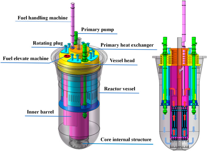
FIGURE 1. Layout of CiADS subcritical LBE cooled reactor.
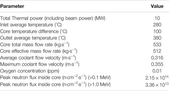
TABLE 1. Main design parameters of the CiADS subcritical reactor.
Similar to the typical fast reactors, the CiADS fuel pin consists of several components in an austenitic stainless steel cladding tube, namely the top/bottom end caps, the tighten spring, the fuel pellets, the upper/lower reflectors, and the lower gas plenum. The conceptual fuel pin design is shown in Figure 2. Taking into account China’s prior experiences in the production and operation of UO2, this type of fuel is selected for the CiADS project to enable near-term deployment. The UO2 pellets with 95.5% theoretical density are adopted to contain fission gases and reduce swelling. Further details about the FA design parameters are provided in Table 2 (Yu et al., 2021):
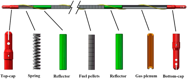
FIGURE 2. Fuel pin of CiADS subcritical reactor.
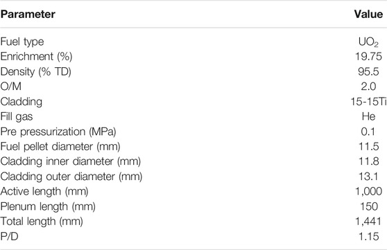
TABLE 2. CiADS fuel pin parameters.
Design Limits
Indicative design limits have been provided by designers to evaluate CiADS fuel pin design and guide fuel performance analysis for long-term steady-state operation. The design limits, presented in Table 3, involve the fuel and cladding temperature, the plenum pressure, and the maximum plastic, creep and swelling strains. As a very first and proof-of-principle facility, the most conservative limits for the CiADS subcritical reactor are taken as a reference in view of absolute safety.
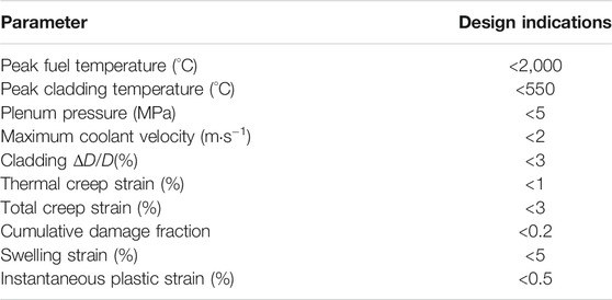
TABLE 3. Indicative design limits for CiADS subcritical reactor.
In particular, the corrosion and erosion problems under the LBE environment are regarded as the most demanding issues. In order to prevent coolant-side aggression due to the strong corrosive behaviour of LBE, limits on cladding temperature and LBE velocity are established and the oxygen-control technology is a must. Therefore, the CiADS subcritical LBE cooled reactor designs have to make sure that the peak cladding temperature is no more than 550 °C, and the maximum LBE velocity is 0.355 m/s, which is far below the design limit. The oxygen concentration in the LBE coolant should be controlled within a reasonable range to avoid the generation of PbO contaminants and to ensure the formation of protective oxide layers on the cladding’s and structural material’s surfaces, which could stop the direct solution reaction. But for non-isothermal loop, it can not only guarantee to form protective oxide layers at high temperatures, but also avoid generating excessive solid lead oxide impurities to block the coolant channel. Based on the requirements above, the reasonable oxygen concentration should be controlled at 0.01 ppm for the CiADS subcritical LBE cooled reactor.
Methods and Modelling
To meet the increasing demands for a detailed understanding of the thermal, mechanical, physical and chemical processes governing the fuel rod behaviors of LMFR, the FUTURE code has been jointly developed. The 1.5D method and finite difference technology were adopted in the FUTURE code to achieve a multi-physics performance analysis for the whole fuel rod. And the code is based on the serial semi-implicit coupling solution, where parameters are transferred according to the model sequence and only the thermo-mechanical coupling is iterated until it converges within one time step.
Outline of FUTURE Code
As the main component of the fuel assembly, the fuel element is the fuel using unit with an independent structure in the reactor. The FUTURE code takes the pellets region, the fission gas plenum and the corresponding claddings as the simulation zone, and this zone is divided into several axial slices as shown in Supplementary Figure S2, while at a given time the rod is analyzed slice by slice. After all the slices have been calculated, each slice needs to be coupled together, which means that quantities such as the inner plenum pressure or the axial friction forces between the pellets and the claddings are determined (axial coupling). Besides, the radial discretization is based on the axial-symmetric hypothesis, so the minimum control unit is a nested node ring and is combined with each other to generate a computing grid.
Under high temperatures and strong irradiation conditions, the fuel experiences phenomena such as fuel restructuring, constituent redistribution, swelling, creep, fission gas release, pellets and claddings interaction, etc. These phenomena and the strong interrelationships among them, as well as the non-linearity of many processes involved, are very complicated and hard to analyze. The FUTURE code simulates these phenomena and their coupling relationships, and tracks the important features with the evolution of the irradiation history to predict the performance of the fuel rods under various operating conditions. Based on the serial semi-implicit computing architectures, the FUTURE code adopts the two-step analysis method, which combines the global thermo-mechanical analysis and local behaviors simulation of fuel rods, to better reflect and deal with the multi-physics problems and multi-scale evolution during operation in the reactor as shown in Supplementary Figure S3. Supplementary Figure S4 depicts the information flow among the modules.
Models and Material Properties
The FUTURE code was developed at first to focus on FRs and deals with serious and multifarious interactions, which only occur in FR cores. However, the CiADS subcritical reactor core possesses two different reactor characteristics because of its special design and unique principle: on the one hand, due to the effects of the external neutron source, the CiADS subcritical reactor core has a much harder neutron energy spectrum, which initiates the spallation and breeding reactions; on the other hand, as a very first and proof-of-principle facility, the most conservative limits for the CiADS subcritical reactor are taken in view of absolute safety. Hence, this subcritical reactor has a much lower keff, linear power and coolant velocity. These conservative design parameters render the CiADS subcritical reactor fuel to behave more like LWR fuels, and the FUTURE code has to be adjusted and updated to apply LWR fuel characteristics under these considerations. According to the preliminary design, the CiADS UO2 fuel will operate with a much lower temperature and burnup, and some of the fuel behaviors for FRs will not occur, such as obvious fuel restructuring, constituent redistribution and fuel and cladding chemical interaction (FCCI). Therefore, these calculating and analysis functions in the FUTURE code were shut down, and the main work focused on the thermo-mechanical behaviors of the UO2 fuel and its performance evolution in this paper. Besides, the code was updated and improved concerning material properties and models suitable for LWRs, including relocation and densification. A brief summary of the main modifications for the CiADS subcritical LBE cooled reactor and crucial parts of the FUTURE code is reported in the following sub-sections, whereas those shut-down functions and models in the FUTURE code will be published elsewhere (Wang et al., 2021).
Thermo-Mechanical Framework
Most phenomena occurring inside fuel pellets are thermally activated, and a good knowledge of the thermal field inside the fuel pin is of paramount importance. In order to calculate the temperature distribution and evolution process inside the fuel rod, the one-dimensional radial energy equations (heat conduction equations) for pellets and claddings are adopted:
whereas the axial energy equation for the coolant is given by:
where
The FUTURE code includes a stress-strain analysis module to simulate the mechanical behaviors of the pellets and claddings. The stress-strain analysis module adopts a more common and effective algorithm with the finite difference method. Based on several assumptions, such as generalized plane strain, continuity condition, and axial symmetry, the calculation is simplified, which only focuses on the global mechanical evolution and the calculation of stresses, strains and the corresponding deformations. Dynamic forces are in general not treated and the solution is therefore obtained by applying the principal conditions of equilibrium and compatibility together with the constitutive relations. These basic equations are combined and derived into a more detailed displacement expression, which is the so-called displacement method to deal with statically indeterminate structures. Except for elastic strain, other strains, such as thermal expansion, swelling, creep, densification and relocation, etc. are given in empirical correlations and substituted into basic equations. The equation of radial equilibrium, which describes the balance between radial and hoop forces, is given by (Lassmann 1992):
and the compatibility equations for small deformation hypothesis are:
whereas the constitutive relations (generalized Hooke’s law) are obtained by:
where
Fuel
In the first phase, UO2 fuels will be loaded in the CiADS subcritical core to test the coupling technology and achieve long-term steady operation. The material database of the FUTURE code contains the physical properties and material parameters of UO2 fuels, which are from the MATPRO (Rossi and Sorbi 2006) and the BISON (Hales et al., 2016) theory manual. Besides, for a more detailed and precise simulation, relocation and densification strains are added in the FUTURE code.
1) Relocation
It is well known that the thermal gradients in an LWR fuel pellet result in the corresponding stress gradients that exceed the fuel fracture stress, causing radial cracks, and afterwards induces radial dimension change of pellets and decreases the width of the gap. But as the volume of pellets increasing rapidly due to swelling, serious FCMI occurs and the status of fuel stresses becomes compressive, cracks healing. Actually, pellet cracking and relocation are very complicated to some extent and can be separated into two mechanisms: 1) The elastic strain prior to cracking is redistributed, and the stress level in the pellet is reduced, while the pellet volume increases; 2) A gross movement of the fuel fragments occurs due to cracking and reduce gap size (Lassmann and Blank 1988). In this paper, the CiADS UO2 fuel was treated as a viscoelastic material; therefore, creep was considered as the main stress relaxation effect. In order to analyze the stress change inside the pellets because of the creep process, the second way was taken to model the effect of UO2 cracking on gap width by adding fuel radial relocation strain. The GAPCON model (Lanning et al., 1978) was adopted to calculate fuel radial relocation strain and modified in this work to reflect the cracks healing process by means of the contact pressure correction method used in the Constant Relocation Model (Siefken, Berna, and Shah 1985; Rashid, Dunham, and Montgomery 2004). This modified GAPCON model is given by:
where
2) Densification
The fuel material is a porous ceramic obtained by powder pressing followed by sintering at high temperatures (generally in the range 1700–1800°C). For the CiADS UO2 porous fuel, the fuel temperature is way too low to activate additional thermal sintering. However, irradiation induced sintering is possible. A large number of atoms are displaced for each fission event, and this energy is sufficient to eliminate part of the remaining small porosity by re-implantation of vacancies from the pores to the bulk, which increases the density of the fuel. Fuel densification is computed using the ESCORE empirical model (Rashid, Dunham, and Montgomery 2004) given by:
where
Cladding
Specific austenitic stainless steels have been developed to be used as cladding materials in fast reactors. The main advantages of these steels are their good thermal creep behaviors, excellent swelling resistance and mechanical properties (Garner 2020). Hence, the cladding material proposed for the CiADS subcritical reactor is austenitic stainless steel 15-15Ti, which is widely adopted for other lead-cooled fast nuclear reactors such as ALFRED and MYRRHA. As the first safety barrier, the properties and behaviors of the claddings obtain much more attention in fuel performance analysis and design evaluation, so creep, swelling and rupture are essential in the modeling. These related computational expressions are also used in the TRANSURANUS code (Luzzi et al., 2014) and reported below.
1) Creep
Based on the data from (Grasso et al., 2013) and the Nabarro-Herring description suggested by (Többe 1975), The formula presented in Eq. 13 is adopted for the thermal creep calculation:
where
And the irradiation induced creep is described by means of the following correlation:
where
2) Swelling
The TRANSURANUS code provides a suitable swelling model for 15-15Ti, which is the derivation of a correlation based on experimental data appropriate for this kind of steel.
And the “Generalized 15-15Ti” correlation is adopted here in Eq. 15, which is aimed at representing the highest swelling values, occurring at 450°C.
where
3) Rupture
The Cumulative Damage Fraction (CDF) model has widely been used to predict the creep-rupture of the fast reactor claddings, which is an empirical model to predict the rupture time. The CDF model based on the Larson-Miller Parameter (LMP) and data from (Filacchioni et al., 1990) has been implemented, and a CDF value smaller than one indicates that claddings do not fail:
where
Coolant
To prevent serious LBE corrosion, the protected oxide layers technology is proposed and adopted in LFRs. Therefore, maintaining the “self-healing” oxide layers on structural material surfaces is important in an LBE-cooled nuclear power system, or the failure of the oxide layer will lead to heavy liquid metal corrosion. The Russian experience on LBE-cooled nuclear reactors indicates that the oxygen concentration and the flow velocity are the two most important factors that affect the oxide layer properties (Zhang 2013), which restrict the CiADS subcritical reactor design. The FUTURE code adopted the long-term behaviors model of the oxide layers in an oxygen-controlled system developed by (Zhang 2013, 2014) to evaluate the status of the cladding’s interface on the LBE side. This model predicts the thickness of the double oxide layers (magnetite layer and spinel layer, which are observed in experiments) due to growth and removal. Based on the mass balance, the kinetics of the magnetite layer growth is expressed by:
where
As for the kinetics of the spinel layer growth, it depends on the real operating conditions:
1) The spinel layer can be expressed by the parabolic law before the magnetite layer is completely removed:
2) If the corrosion rate or the iron removal rate by the flow is less than that of the iron diffusion rate through the spinel layer, the thickness of the spinel can be calculated by the linear growth law:
3) With the thickness of the spinel layer increasing, the iron diffusion rate through the spinel and the iron mass transfer rate by the liquid metal at the oxide/liquid interface equal to each other, then Tedmon equation is applied:
where
Results and Analysis
The FUTURE code takes the fuel active region and the fission gas plenum of the hottest pin as the simulation zone, and the active region is divided into ten axial slices, which means 10 cm long for each slice. Besides, there are 20 and 10 radial nodes for the pellets and the claddings, respectively, to describe the detailed distribution of quantities. The corresponding fuel design parameters presented above have been inputted into the FUTURE code, while neutronics analysis of the CiADS subcritical reactor fuel pin has been carried out by means of the Monte Carlo code. Figure 3 shows the average linear power history for the hottest pin, and the burnup evolution is calculated by the FUTURE code. According to the design of three yearly cycles, the power only degrades a little from the beginning of life (BoL) to the end of life (EoL). And the axial discretization of the fuel pin is illustrated in Figure 4, including the axial distribution of linear power and coolant pressure. Also, it is worth noting that the coolant pressure is provided by the LFR-Sub code, which is a sub-channel analysis code of LBE cooled reactor developed by the IMP-CAS(Liu et al., 2021).

FIGURE 3. History of linear power for hottest pin.
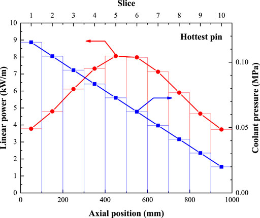
FIGURE 4. Axial distribution of linear power and coolant pressure.
In this section, FUTURE results are explained, focusing on the heat-transfer and stress-strain mechanisms for the CiADS UO2 fuel. And also, further analysis is shown to evaluate the fuel performance according to the design limits.
Heat-Transfer
1) Code Comparison
Due to R&D demands for the CiADS reactor, the FUTURE code, the LFR-sub code and the RELAP5 code are used to analyze heat-transfer characteristics of the CiADS subcritical reactor. In reality, it is well known that these three kinds of codes are inclined to deal with different problems: the FUTURE code, the same as most fuel performance analysis codes, focuses on the multi-physics coupling, and its advantage is to describe the much more detailed distribution and evolution of quantities, and also the interaction among these multi-physics problems inside the fuel pin; as for the sub-channel analysis code, the LFR-sub code takes the thermal-hydraulic issues on assemblies or cores scale as the most critical points, which provides more accurate computing on the fluid side; and the RELAP5 code is an excellent system analysis code for best-estimate transient simulation of the LWR coolant systems during postulated accidents; furthermore, a generic modeling approach is adopted that permits a variety of thermal-hydraulic systems. Here, the RELAP5 code has been improved to simulate the CiADS LBE cooled subcritical reactor (Zhang et al., 2018). Although these three kinds of codes emphasize different analyses, all of them can model the heat-transfer process from pellet to coolant. Therefore, the results of these codes are compared to reveal similarities and differences.
Figure 5 shows the axial temperature distribution at the fuel centerline, the cladding inner and outer surface, and the coolant. It is worth noting that the results of the FUTURE code are only illustrated at the initial state, since the heat transfer ability is enhanced as dimension increasing resulted from swelling and creep. This behavior of thermo-mechanical coupling is not considered in the LFR-sub code and the RELAP5 code. When ignoring differences, these three kinds of codes give very same trends for temperature distribution: 1) the temperature of LBE increases along the axial position, this is because the coolant is heated in series, and the slope of coolant depends on the distribution of linear power; 2) the shape of fuel centerline temperature is similar to the distribution of linear power, but it is a little higher than power distribution at the latter half of fuel pin, which means the shape of fuel centerline temperature doesn’t only rely on the power, but also on the heat exchange capability of the coolant; 3) as for the axial temperature distribution at the cladding inner and outer surface, they are way too same as that of the coolant temperature, which shows the heat exchange between cladding and LBE is such excellent that the temperature gap is very small.
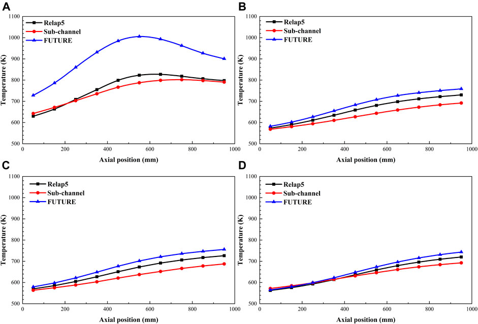
FIGURE 5. Code comparisons about heat-transfer results. (A) Fuel center temperature; (B) Cladding inner surface temperature; (C) Cladding outer surface temperature; (D) Coolant temperature.
The differences among these three codes exist mainly because of the methods, the models and the numerical discretization. As far as the coolant temperatures are concerned, the comparison is: 1) The LFR-sub code takes the subchannel analysis method to deal with the thermo-hydraulic problems, while this method divides the flow channels between rod bundles or fuel assemblies. The fluids exchange energy and momentum with the adjacent channels. Meanwhile, the effects of turbulent mixing and convective heat transfer around the wire are simulated. In conclusion, the coolant is mixed thoroughly in the axial and transverse directions, resulting in a more considerable coolant pressure drop and a more even temperature distribution that is lower than those codes without considering the transverse mixing. 2) The RELAP5 code (Fletcher and Schultz 1992), as a system analysis code, adopts a lumped parameter single-channel model to describe the flow and heat transfer phenomenon in the core. The calculated channel is regarded as an isolated and closed flow channel with no mass, momentum and energy exchanges with other channels on the whole height of the core. As a result, the axial temperature distribution of the coolant is higher than LFR-sub’s result. 3) The FUTURE code focuses on the physics process inside the fuel, while the temperature of the coolant is just calculated based on the one-dimensional axial convection heat transfer equation, regardless of quality and momentum change. Hence, the result of the FUTURE code on the LBE side is higher than that of the LFR-sub code, and the maximum temperature difference is about 51 K.
The heat transfer inside the fuel is also carried out by means of different methods: 1) The LFR-sub code adopts the method of weighted residuals in the radial direction and finite difference for time derivatives and axial space derivatives to solve the two-dimensional heat conduction equation. Therefore, as can be seen from Figure 5A, the fuel centerline temperature is flatter due to the axial heat transfer process of the fuel. 2) The RELAP5 code takes the finite difference method and the Crank-Nickelson scheme to solve the one-dimensional heat conduction equation, and five nodes are used in space discretization as much as the LFR-sub code. The maximum deviation is 36 K compared with the LFR-sub’ result. On the one hand, it results from a higher coolant temperature. On the other hand, the most central node of the RELAP5 code is much closer than the LFR-sub code, causing higher values. And the different methods adopted by the LFR-sub code and the RELAP5 code have little influence on modeling. 3) The FUTURE code also adopts the same method as the RELAP5 code does. However, more nodes are used to describe the distribution of quantities (20 for fuel and 10 for cladding), which is necessary especially considering the obvious thermal conductivity degradation with the rise of temperature. Besides, the thermal-mechanical iteration and a series of interactions could provide a more real simulation, causing the calculated fuel centerline temperature of the FUTURE code to be higher than that of the RELAP5 code with a maximum deviation of 182 K.
2) Temperature Evolution
Figure 6 shows the distribution evolution of the fuel temperatures at the hottest slice during the irradiation. The temperature distribution inside the fuel is controlled by the heat transfer process. It seems like an approximate parabola in the pellet because of the nonlinear thermal conductivity due to temperature dependency, and near-linear in the cladding due to excellent heat transfer. The distribution and evolution of the fuel temperatures are both strongly influenced by the gap conductance. On the one hand, the lower gap conductance causes a more considerable temperature drop between the pellet and cladding; on the other hand, the maximum fuel temperature occurs at the minimum gap conductance, which occurs in the first stage of the irradiation history. The real heat transfer is not independent, and it interacts with mechanical behaviors and other fuel phenomenons. As shown in Supplementary Figure S5, the dimension of the pellet changes because of swelling and creep as irradiation increases, which means the reduction of gap size and the improvement of gap conductance. Hence, the fuel temperatures will descend continuously. Afterwards, the conductance starts to sharply increase due to the gap closing and, when the closure is complete, the inner and outer fuel temperatures are steady to an almost constant level (the fuel thermal conductivity degradation counterbalances the increase of the gap conductance).
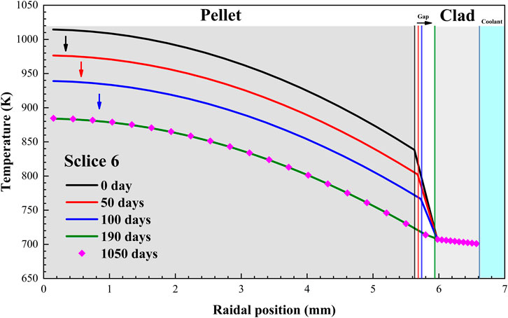
FIGURE 6. Temperature evolution of the hottest slice.
Witness the fuel centerline temperature evolution for some slices at different axial positions of the fuel in Figure 7. It can be found that the effect of thermo-mechanical coupling appears and is a little different for each slice, and this interaction is explained here focusing on the impact of deformation to heat transfer. As for the counteraction, it will be illustrated adequately in the next section. The FUTURE code considers six kinds of strain in the radial direction, including elastic, creep, swelling, thermal, densification and relocation. Except for elastic strain and thermal expansion, other strains are time-dependent and will change as time increasing. Therefore, the initial deformation of pellet and gap width is controlled by elastic strain and thermal expansion, which causes a much higher temperature at the very first beginning. Afterward, other strains increase rapidly to reduce the gap width and finally make the gap close, which improves the conductance. As shown in Figure 8, the fuel centerline temperature drops continuously until contacting, after that, there is no apparent temperature change because of no obvious total radial strain increasing. Besides, what is very important is that these strains strongly rely on temperature and linear power, so the slice with lower initial temperature and power contacts later, and the temperature difference is much smaller. Figure 8 indicates that the shape of axial temperature distribution changes step by step, which is resulted from each slice contacting successively.
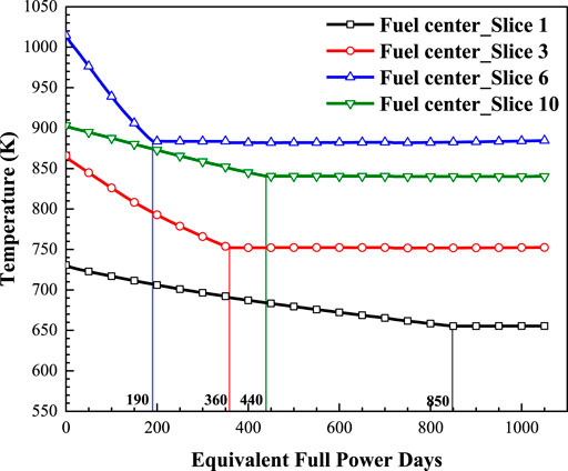
FIGURE 7. Evolution of the fuel center temperature for given slices.
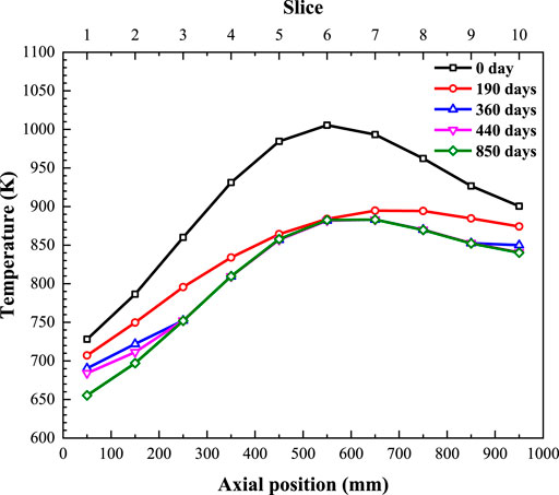
FIGURE 8. Axial distribution evolution of fuel center temperature.
Stress-Strain
1) Fuel
The FUTURE code takes pellets as visco-elastic materials and considers six kinds of strain in the radial direction, including elastic, creep, swelling, thermal, densification and relocation, and they are classified into recoverable, isotropic and anisotropic strains. Except for elastic strain and thermal expansion, other strains are time-dependent and will change as time increasing. Among these strains, the thermal expansion only depends on temperature and occurs anytime. When the power initials, the very steep temperature gradient arises inside the pellet due to the low and nonlinear thermal conductivity, and following is the quite large thermal stress. Materials deform elastically under this high-stress status, and finally, the stress and strain are in balance. Both elastic strain and thermal expansion are recoverable, as shown in Figure 9, which means they vanish without stress and heat.
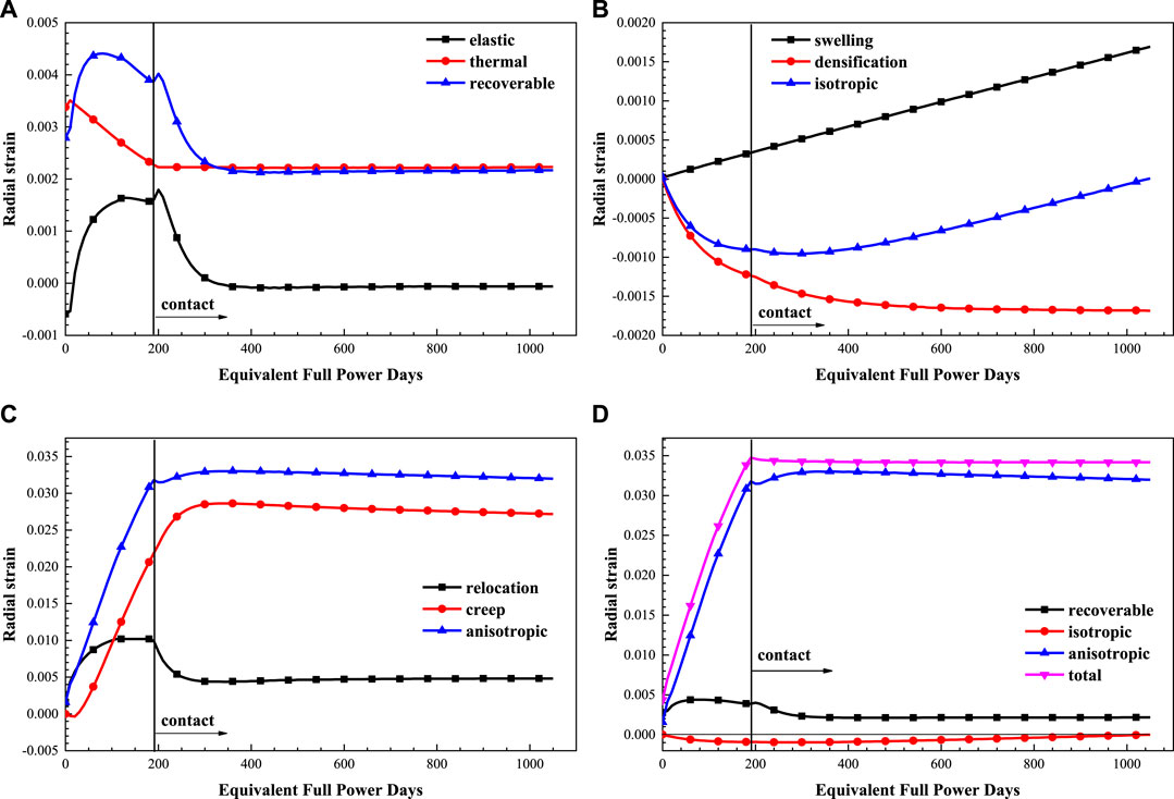
FIGURE 9. Evolution of fuel strains. (A) Recoverable strains; (B) Isotropic strains; (C) Anisotropic strains; (D) Total strains.
At low temperatures, under about 1,400 °C, oxide fuel is brittle with rupture stress of about 130 MPa(Pelletier and Guérin 2020; Van Uffelen and Pastore 2020). Figure 10C shows that initial hoop stress at the periphery of the pellet inside hottest slice six is more than the rupture limit, which means that oxide fuel pellets start to crack at the beginning of the first power rise though the power is not that high. Therefore, pellet cracking is the first phenomenon occurring in the oxide fuel pellet at the beginning of life, and the modified GAPCON model is adopted in FUTURE to calculate relocation strain due to cracking. Relocation is like logarithmic growth and will be steady at fixed burnup. Once the FCMI occurs, the pellets will be compressive, and cracks healing. At that time, the relocation strain is adjusted by contact pressure and reduced. The modeling of creep is based on the von Mises assumption, and is allocated to three directions according to Prandtl-Reuss flow laws. Figure 9C indicates that creep increases rapidly under high-stress conditions, and as a result, the stress is relaxed. Furthermore, the increase of pellet dimension is mainly because of creep and relocation, which induce the gap closure.
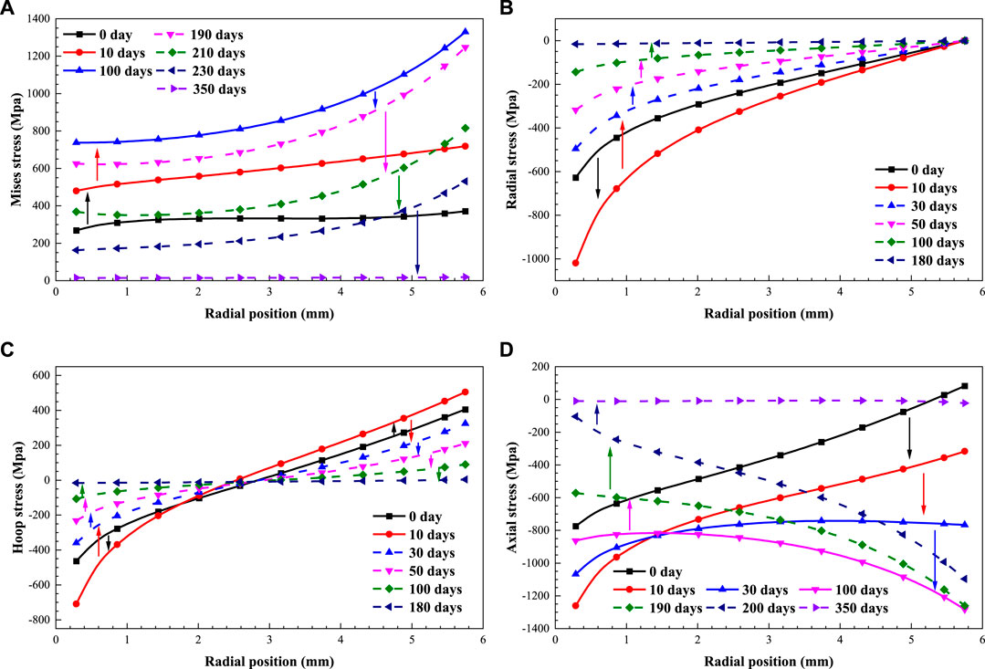
FIGURE 10. Evolution of fuel stresses. (A) Mises stress; (B) Radial stress; (C) Hoop stress; (D) Axial stress.
The CiADS UO2 fuel is a porous ceramic obtained by powder pressing followed by sintering at high temperatures (generally in the range 1700–1800 °C). During irradiation, the CiADS fuel temperature is way too low to activate additional thermal sintering. But athermal sintering activation is possible. The remaining small porosity vanishes by re-implantation of vacancies from the pores to the bulk, and eventual annihilation on sinks, e.g., grain boundaries (Olander 1976), and thus, densification occurs. Simultaneously, the fuel material swells due to several phenomena: the accumulation of non-soluble species, single or complex defects, the creation of new cells in the lattice and the formation of precipitates. Because of the low burnup and temperature of the CiADS fuel, the swelling is much lower and increases linearly. The combination of densification and swelling phenomena causes density to maintain near the initial value at EoL, as shown in Figure 9D.
Figure 10 shows the distribution and evolution of stress components and Mises stress, and full lines reflect the rising process of stress state, while dotted lines the decreasing process. The initial high-stress status originates from differences in thermal expansion induced by a steep temperature gradient. After that, the relocation strain is exerted in the radial direction, which increases the stress further. However, creep works soon afterwards as the stress increases. The pellet turns to flow along the path of stress, which releases the potential energy by deforming, and also, the stress is relaxed. Witness Figure 10A, Mises stress reaches such a high value and may be deviated from natural stress. It is because plasticity and the structure effect of cracking are not considered here. And Figure 10C indicates that the hoop stress at the periphery of the pellet of axial stress is tensile, which causes θ cracking along the radial direction. As for the axial stress in Figure 10D, its evolution could be attributed to the synergistic effect of generalized plane strain assumption and creep flow. It appears to have different shape characteristics over time. On the one hand, the generalized plane strain assumption used in mechanical calculation controls the axial strains by adjusting stress in different radial positions for the whole plane and keeps the original axial plane still, which causes the higher pressure at the inner of pellet where significant axial expansion occurs. And at the periphery, it becomes lower or even tension to adjust the small outer deformation. On the other hand, creep works overtime, and the higher the temperature is, the larger the creep rate is. It means the stress will be relaxed in the center prior to that at the periphery, so the transition occurs, and curves intersect. At last, axial stress is also relaxed to a very small value due to creep flow.
2) Cladding
For CiADS UO2 fuel, the strain and stress of cladding are much small and simple compared with those inside the pellet. Firstly, due to the flat temperature gradient illustrated in Figure 6, 15-15Ti cladding tends to deform due to relatively uniform thermal expansion, and thus, stress is much small before gap closure, as shown in Figure 11. Besides, elastic, swelling, and creep are also close to the very small values and keep steady under such low temperature and burnup conditions, as shown in Figure 12. Swelling is usually modeled (Waltar et al., 2011) considering an incubation period at low displacements per atom (dpa) where no swelling occurs (Garner 2020), while FUTURE gives a 9.8 dpa at EoL for CiADS cladding. However, once the FCMI happens, elastic and creep strains changes. The contact links the interfaces, and the stress spreads from pellet to cladding, which increases the stress of cladding but still no plasticity occurring. As a result, cladding moves outwards, and elastic and creep strains in the radial direction increase reversely to resist this deformation. This process shows that a thin-walled cylinder, just like the cladding, bears inner pressure and tends to expand outwards, and meanwhile, the radial dimension of cladding shrinks. It is found in Figure 11A that Mises stress rises gradually after gap closure because of contact pressure increasing and only drops a little at EoL due to small creep quantities. Besides, the generalized plane strain assumption and creep relaxation also work here to adjust the inner and outer stress shown in Figure 11D, but there is no transition or curves intersecting with little axial stress increasing.
3) FCMI
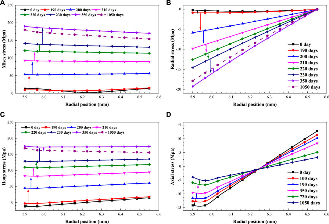
FIGURE 11. Evolution of cladding stresses. (A) Mises stress; (B) Radial stress; (C) Hoop stress; (D) Axial stress.
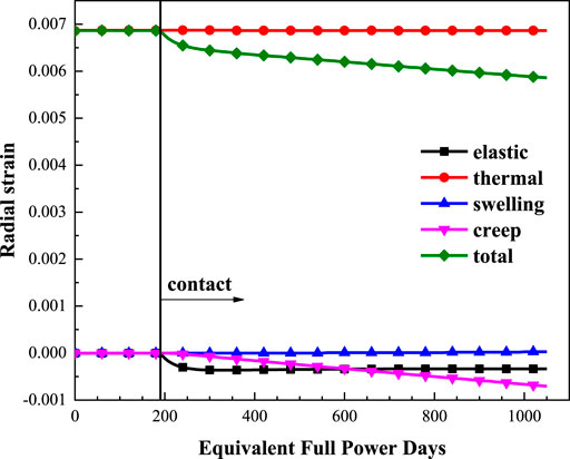
FIGURE 12. Evolution of cladding strains.
At low temperatures (less than 1300 K), the mobility of fission-gas atoms is too low to permit appreciable gas-atom movement, either to release surfaces or even to sites where bubbles can form (Olander 1976). With such low temperature and burnup, the fission gases produced in CiADS fuel are frozen in the solid matrix. Only the gas formed very close to an external surface can escape, which hardly causes any fission gas to release to the plenum. And the plenum pressure is almost constant. The evolution of the gap size, the outer radius of the pellet, the inner and outer radius of cladding along the axial direction are depicted in Figure 13. The dimension of cladding does not change a lot, even after gap closure. According to the previous analysis, the gap size dynamics are driven mainly by the pellet deformation due to large relocation and creep. The axial slices contact in succession according to the temperature distribution, which means it is earlier for the hotter slice to contact. It is found in Figure 14 that the contact pressure will increase rapidly to the maximum, accompanied by the inner stress rising. After that, the contact pressure will drop slightly because of stress relaxation by creep. Besides, the most important phenomenon is that the contact pressure will get a more significant value for the slice which contacts later. It is the consequence of the same reason mentioned above. The slice contacting later has a much lower temperature, which means the creep rate is low, and the re-balance process of stress relaxation is slow. In conclusion, the colder slice contacts later, but will create a larger contact pressure. Due to the low swelling rate of oxide fuel and its high creep rate, FCMI does not play such a crucial role, especially for CiADS UO2 fuel.
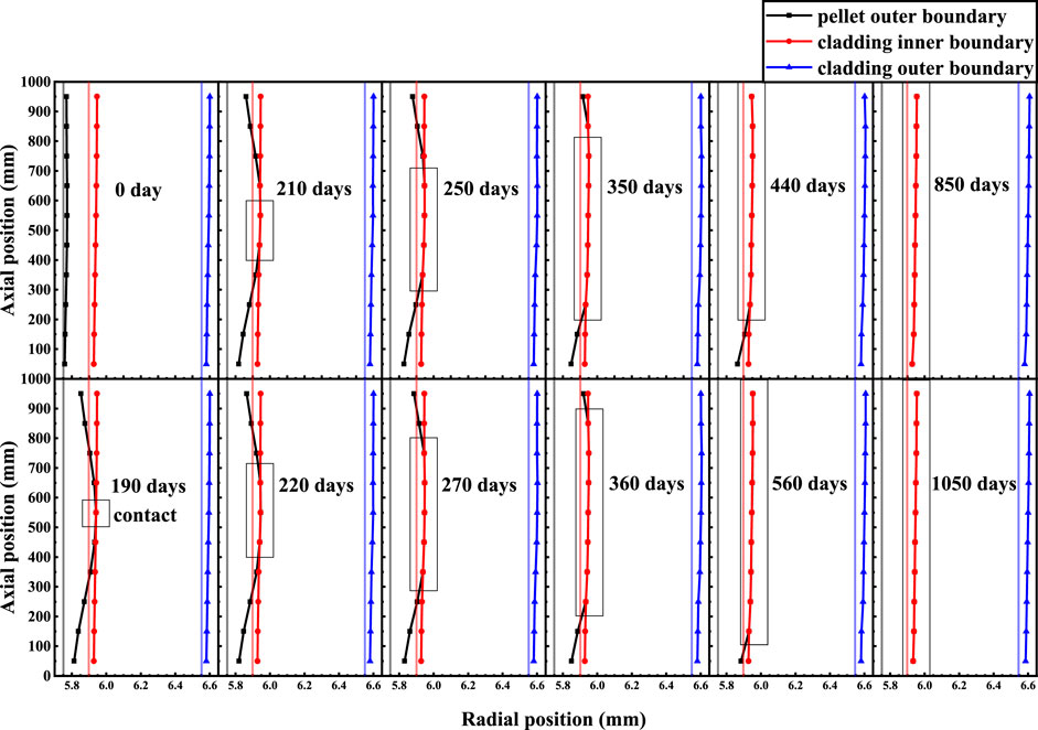
FIGURE 13. Evolution of gap status.
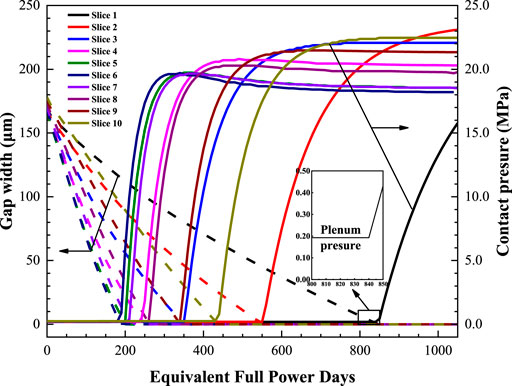
FIGURE 14. Evolution of gap width and contact pressure.
It is worth noting that the first closure happens in the hottest slice six at about 190 days. Though compared with LWR fuel, it is way too early for the first contacting, especially considering the cladding’s creep inwards for LWR because of higher coolant pressure. The reasons may be: 1) the modified GAPCON model provides a large value of relocation, which may be not suitable for CiADS fuel analysis; 2) to ensure high computational efficiency, creep flow is updated over a large time step (10 days), so the accumulation of creep is also large with using the stress of the previous time. All of these will be tested in detail and modified in the latter research.
Design Evaluation
This section illustrates the design evaluation of CiADS UO2 fuel for long-term operating according to the indicative design limits shown in Section 2.4. In reality, UO2 fuels will be loaded in the CiADS subcritical core to test the coupling technology and achieve the long-term steady operation at the first phase, and as a proof-of-principle facility, the most conservative design for the CiADS subcritical reactor is taken in view of absolute safety. Therefore, most of the modeling results are way too low compared to the limits. The peak fuel temperature is 1005 K, while the peak cladding temperature is 759 K. The plenum pressure stays at around 0.2 MPa from BoL to EoL, because there is hardly any fission gas release under such low temperature and burnup. As the first barrier, the evaluation of cladding is much more critical. Figure 15 shows the ultimate limits for 15-15Ti cladding, which contains yield stress, ultimate tensile strength and rupture strain. Under design operating conditions, the CiADS cladding will not bear very high external loads, temperature and even temperature gradient.
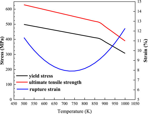
FIGURE 15. Ultimate limits for 15-15Ti cladding modeling.
The stress inside cladding is far below the ultimate tensile strength and the yield stress, which means rupture and plasticity will not happen. And also, the creep and swelling of cladding are very small. Although all of these stress-strain evaluations of cladding means its normal usage, problems may still exist in LBE corrosion. Mainly because of axial temperature distribution, the growth of protective oxide layers tends to be different along the axial direction. Figures 16, 17 show the growth of oxide layers, and the thickness of oxide layers for different slices varies a lot. In the exit section, the protective oxide layers fully grow at a relative temperature. However, the oxide layers are very thin near the coolant inlet, which cannot form enough thickness to resist erosion or peeling and protect inner cladding. It is worth noting that this problem occurs in the non-isothermal loop and is hard to solve because direct dissolution reactions are sometimes severe. Further research and evaluation focusing on this problem will be carried out in the future.
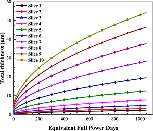
FIGURE 16. The growth of oxide layers for different slices.
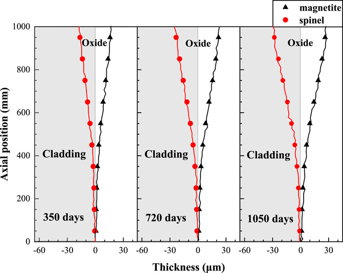
FIGURE 17. The axial distribution and its evolution of oxide layers.
Conclusion
In this paper, the conceptual design of the CiADS subcritical LBE cooled reactor is introduced. In the first phase, UO2 fuels will be loaded in the subcritical core to test the coupling technology and achieve long-term steady operation. The FUTURE code has been modified and employed in the fuel performance analysis and evaluation of pin design for CiADS UO2 fuel. Development efforts have been dedicated to the extension of the FUTURE code for analyzing CiADS UO2 fuel. Relocation and densification models are added, and fission gas release model is replaced according to the CiADS fuel characteristics. The main work focuses on the thermo-mechanical behaviors and performance evolution of UO2 fuel, and design evaluation is also carried out.
Due to R&D demands for CiADS, FUTURE, LFR-sub, and RELAP5 are used to analyze heat-transfer characteristics of CiADS subcritical reactor. FUTURE emphasizes multi-physics modeling inside fuel, and there is no doubt that the fuel temperature calculation of FUTURE is much more accurate. The LFR-sub code takes the thermal-hydraulic problems on assemblies or cores scale as the most critical points, which provides more accurate computing on the fluid side. RELAP5, as an excellent system safety analysis code, links all the relative thermal components and is more balanced but rough among these three codes. The maximum temperature difference is about 51 K in LBE, and 182 K at the fuel center. FUTURE results showed that the maximum temperature was 1014 K at initial operating and gradually dropped to 884 K at EoL due to the reduction of gap width. The heat-transfer and stress-strain process interact with each other, which causes the shape of axial temperature distribution changing step by step because of different axial deformation. According to the preliminary design, the CiADS UO2 fuel exhibits good performance, and the main parameters are far below the indicative limits. The FCMI is not very serious, and the permanent cladding strains and CDF are small and even negligible, thanks to the low level of the temperature and corresponding stress.
However, some critical issues may still exist in the modeling. On the one hand, FUTURE results showed that oxide layers were very thin in the entrance from BoL to EoL, which could not form enough thickness to resist erosion or peeling and protect inner cladding. Therefore, further research and experiments will be carried out on the LBE flow and material experimental circuit STELA, which is expected to be completed in 2021 by IMP-CAS. On the other hand, it was found that the first gap closure of CiADS UO2 fuel was too early, probably because of large dislocation and creep. Subsequent updates and sensitivity analysis in the FUTURE code will be implemented to modify and test these two models. At last, it is worth noting that the results provided meaningful feedback to the reactor designers in the conceptual design of CiADS subcritical LBE cooled reactor, and the FUTURE code has been proved an excellent tool to evaluate the synergy of the phenomena occurring in the fuel pin and their impact on the fuel design improvement.
Data Availability Statement
The raw data supporting the conclusion of this article will be made available by the authors, without undue reservation.
Author Contributions
GW: code development and calculation. LG: study and design of reactor. DY: fuel performance analysis and evaluation. All authors contributed to the article and approved the submitted version.
Funding
The Research on key technology and safety verification of primary circuit has the Grant No. 2020YFB1902104 (GW, LG, DY) and the funder the Experimental study on thermal-hydraulics of fuel rod bundle has the Grant No. Y828020XZ0 (GW, LG).
Conflict of Interest
The authors declare that the research was conducted in the absence of any commercial or financial relationships that could be construed as a potential conflict of interest.
Publisher’s Note
All claims expressed in this article are solely those of the authors and do not necessarily represent those of their affiliated organizations, or those of the publisher, the editors and the reviewers. Any product that may be evaluated in this article, or claim that may be made by its manufacturer, is not guaranteed or endorsed by the publisher.
Supplementary Material
The Supplementary Material for this article can be found online at: https://www.frontiersin.org/articles/10.3389/fenrg.2021.732801/full#supplementary-material
References
Abderrahim, H. A., Kupschus, P., Malambu, E., Benoit, P., Van Tichelen, K., Arien, B., et al. (2001). MYRRHA: A Multipurpose Accelerator Driven System for Research & Development. Nucl. Instr. Methods Phys. Res. Sect. A: Acc. Spect. Detect. Assoc. Equip. 463 (3), 487–494. doi:10.1016/s0168-9002(01)00164-4
Ahmad, A., Suzanne, L., Parks, G. T., and Parks, S. L. (2012). The Effect of Beam Interruptions on the Integrity of ADSR Fuel Pin Cladding: A Thermo-Mechanical Analysis. Ann. Nucl. Energ. 46, 97–105. doi:10.1016/j.anucene.2012.03.021
Baetslé, L. H., Wakabayashi, T., and Sakurai, S. (1988). “Status and Assessment Report on Actinide and Fission Product Partitioning and Transmutation,” in the Fifth OECD/NEA Information Exchange Meeting on Actinide and Fission Product Partitioning and Transmutation. Mol, Belgium: SCK-CEN.
International Atomic Energy Agency (2003). Status and Advances in MOX Fuel Technology. Technical Reports Series No. 415 (Vienna: IAEA).
Carbol, P., Wegen, D. H., Wiss, T., Fors, P., Jegou, C., and Spahiu, K. (2012). “Spent Nuclear Fuel as Waste Material,” in J Reference Module In Materials Science Materials Engineering.
Delage, F., Ramond, L., Gallais-During, A., and Pillon, S. (2020). Actinide-Bearing Fuels and Transmutation Targets.
Delage, F., Belin, R., Chen, X.-N., D’Agata, E., Klaassen, F., Knol, S., et al. (2011). ADS Fuel Developments in Europe: Results from the EUROTRANS Integrated Project. Energ. Proced. 7, 303–313. doi:10.1016/j.egypro.2011.06.039
Filacchioni, G., De Angelis, U., Ferrara, D., and Pilloni, L. (1990). “Mechanical and Structural Behaviour of the Second Double Stabilized Stainless Steels Generation,” in Fast Reactor Core and Fuel Structural Behaviour (Thomas Telford Publishing), 255–261.
Garner, F. A. (2020). Radiation-Induced Damage in Austenitic Structural Steels Used in Nuclear Reactors, in Comprehensive Nuclear Materials 2nd Edn, 57–168. doi:10.1016/b978-0-12-803581-8.12067-3
Grasso, G., Petrovich, C., Mikityuk, K., Mattioli, D., Manni, F., and Gugiu, D. (2013). “Demonstrating the Effectiveness of the European LFR Concept: the ALFRED Core Design,” in J Proceedings of Fast Reactors Related Fuel Cycles (Paris: Safe Technologies Sustainable Scenarios).
Gu, L., and Su, X. (2021). Latest Research Progress for LBE Coolant Reactor of China Initiative Accelerator Driven System Project. J. Front. Energ., 1–22. doi:10.1007/s11708-021-0760-1
Hales, J. D., Williamson, R. L., Novascone, S. R., Pastore, G., Spencer, B. W., Stafford, D. S., Gamble, K. A., et al. (2016). BISON Theory Manual the Equations behind Nuclear Fuel Analysis. Idaho Falls, ID (United States): Idaho National Lab. INL.
International Atomic Energy Agency (2015). Status of Accelerator Driven Systems Research and Technology Development. International Atomic Energy Agency.
Kelly, J. E. (2014). Generation IV International Forum: A Decade of Progress through International Cooperation. Prog. Nucl. Energ. 77, 240–246. doi:10.1016/j.pnucene.2014.02.010
Kittel, J. H., Frost, B. R. T., Mustelier, J. P., Bagley, K. Q., Crittenden, G. C., and Van Dievoet, J. (1993). History of Fast Reactor Fuel Development. J. Nucl. Mater. 204, 1–13. doi:10.1016/0022-3115(93)90193-3
Lanning, D. D., Mohr, C. L., Panisko, F. E., and Stewart, K. B. (1978). GAPCON-THERMAL-3 Code Description. Richland, Wash.(USA): Battelle Pacific Northwest Labs.
Lassmann, K., and Blank, H. (1988). Modelling of Fuel Rod Behaviour and Recent Advances of the Transuranus Code. Nucl. Eng. Des. 106 (3), 291–313. doi:10.1016/0029-5493(88)90292-0
Lassmann, K. (1992). TRANSURANUS: a Fuel Rod Analysis Code Ready for Use. J. Nucl. Mater. 188, 295–302. doi:10.1016/b978-0-444-89571-4.50046-3
Liu, J., Peng, T., Su, X., and Gu, L. (2021). Development and Verification of a Subchannel Code for lead Cooled Fast Reactor Fuel Assembly with Wire Spacers. J. At. Energ. Sci. Technol. (in Chinese). doi:10.7538/yzk.2020.youxian.0864
Luzzi, L., Cammi, A., Di Marcello, V., Lorenzi, S., Pizzocri, D., and Van Uffelen, P. (2014). Application of the TRANSURANUS Code for the Fuel Pin Design Process of the ALFRED Reactor. Nucl. Eng. Des. 277, 173–187. doi:10.1016/j.nucengdes.2014.06.032
Maschek, W., Chen, X., Delage, F., Fernandez-Carretero, A., Haas, D., et al. (2008). Accelerator Driven Systems for Transmutation: Fuel Development, Design and Safety. J. Prog. Nucl. Energ. 50 (2-6), 333–340. doi:10.1016/j.pnucene.2007.11.066
Mueller, A. C. (2009). Prospects for Transmutation of Nuclear Waste and Associated Proton-Accelerator Technology. Eur. Phys. J. Spec. Top. 176 (1), 179–191. doi:10.1140/epjst/e2009-01157-8
NEA (2002). “Accelerator-Driven Systems (ADS) and Fast Reactors (FR),” in Advanced Nuclear Fuel Cycles. A Comparative Study.
Olander, D. R. (1976). Fundamental Aspects of Nuclear Reactor Fuel Elements: Solutions to Problems. Berkeley (USA): California University.
Pelletier, M., and Guérin, Y. (2020). “Fuel Performance of Fast Spectrum Oxide Fuel,” in Comprehensive Nuclear Materials (Elsevier), 72–105. doi:10.1016/b978-0-12-803581-8.11690-x
Peng, T., Gu, L., Wang, D., Li, J., Zhu, Y., and Qin, C. (2017). Conceptual Design of Subcritical Reactor for China Initiative Accelerator Driven System. J. At. Energ. Sci. Technol. 51 (12), 2235–2241. doi:10.7538/yzk.2017.51.12.2235
Rashid, Y., Dunham, R., and Montgomery, R. (2004). Fuel Analysis and Licensing Code: FALCON MOD01. EPRI Report.
Rossi, L., and Sorbi, M. (2006). MATPRO: a Computer Library of Material Property at Cryogenic Temperature. J. Care-note--018-hhh, Supercond. Database.
Rubbia, C., Roche, C., Rubio, J. A., Carminati, F., Kadi, Y., Mandrillon, P., et al. (1995). Conceptual Design of a Fast Neutron Operated High Power Energy Amplifier.
Siefken, L. J., Berna, G. A., and Shah, V. N. (1985). FRAP-T6: A Computer Code for the Transient Analysis of Oxide Fuel Rods. Nucl. Eng. Des. 88 (3), 341–355. doi:10.1016/0029-5493(85)90169-4
Többe, H. (1975). Das Brennstabrechenprogramm IAMBUS zur Auslegung von Schnellbrüter-Brennstäben. J. Interatom. Technischer Bericht.
Van Uffelen, P., and Pastore, G. (2020). “Oxide Fuel Performance Modeling and Simulation,” in Comprehensive Nuclear Materials. Elsevier, 363–416. doi:10.1016/b978-0-12-803581-8.11693-5
Wade, D. C. (2000). “Safety Considerations in Design of Fast Spectrum ADS for Transuranic or Minor Actinide Burning: A Status Report on Activities of the OECD-NEA Expert Group,” in Information Meeting on Actinide and Fission Product Partitioning & Transmutation.
Wang, G., Gu, L., Yu, R., Wang, T., Wang, Z., He, Y., et al. (2021). Development and Preliminary Verification of Oxide Fuel Performance Analysis Code FUTURE for Lead-based Fast Reactor. J Atomic Energy Science Technology. (in Chinese). doi:10.7538/yzk.2021.youxian.0343
Xu, H., Yuan, H., and Luo, P. (2015). China's Accelerator Driven Sub-critical System (ADS) Program. J. Aapps Bull. 25 (3).
Yu, R., Gu, L., Sheng, X., Li, J., Zhu, Y., Zhang, L., et al. (2021). Review of Fuel Assembly Design in lead‐based Fast Reactors and Research Progress in Fuel Assembly of China Initiative Accelerator Driven System. Int. J. Energ. Res. 45 (8), 11552–11563. doi:10.1002/er.6569
Zhan, W-l., and Xu, H. S. (2012). Advanced Fission Energy Program-ADS Transmutation System. J. Bull. Chin. Acad. Sci. 27 (3), 375–381. doi:10.3969/j.issn.1000-3045.2012.03.017
Zhang, J. (2013). Long-term Behaviors of Oxide Layer in Liquid lead–bismuth Eutectic (LBE), Part I: Model Development and Validation. Oxid. met. 80 (5), 669–685. doi:10.1007/s11085-013-9450-7
Zhang, J. (2014). Long-Term Behaviors of Oxide Layer in Liquid Lead–Bismuth Eutectic (LBE), Part II: Model Applications. Oxid. met. 81 (5), 597–615. doi:10.1007/s11085-014-9469-4
Keywords: CiADS, subcritical reactor, LBE, UO2 fuel, performance analysis, FUTURE code
Citation: Wang G, Gu L and Yun D (2021) Preliminary Multi-Physics Performance Analysis and Design Evaluation of UO2 Fuel for LBE-Cooled Subcritical Reactor of China Initiative Accelerator Driven System. Front. Energy Res. 9:732801. doi: 10.3389/fenrg.2021.732801
Received: 29 June 2021; Accepted: 22 September 2021;
Published: 15 October 2021.
Edited by:
Wenzhong Zhou, Sun Yat-sen University, ChinaReviewed by:
Rong Liu, South China University of Technology, ChinaJiankai Yu, Massachusetts Institute of Technology, United States
Copyright © 2021 Wang, Gu and Yun. This is an open-access article distributed under the terms of the Creative Commons Attribution License (CC BY). The use, distribution or reproduction in other forums is permitted, provided the original author(s) and the copyright owner(s) are credited and that the original publication in this journal is cited, in accordance with accepted academic practice. No use, distribution or reproduction is permitted which does not comply with these terms.
*Correspondence: Long Gu, Z3Vsb25nQGltcGNhcy5hYy5jbg==