 Kai Xiong
 Yong-Li Yin3
- 1School of Mechanical Engineering and Automation, Harbin Institute of Technology, Shenzhen Graduate School, Shenzhen, China
- 2Space Science and Technology Institute, Shenzhen, China
- 3National Key Laboratory of Human Factors Engineering, China Astronaut Research and Training Center, Beijing, China
Excess hydrogen and carbon dioxide will be produced during the operation of life support systems in the habitable confined space (HCS), and to eliminate the two excess gases by converting them into methanol is of great significance for maintenance of atmospheric balance and protection of crew’s life safety. Due to the limited energy supply ability within the HCS, it is important for the system of carbon dioxide hydrogenation to methanol (CDHM) to operate with high energy efficiency to reduce unnecessary external energy consumption and internal energy loss. In this paper, the exergy analysis method is adopted for exergy efficiency improvement. Specifically, a parametric study on the exergetic performance of the CDHM system is conducted based on the three key working condition parameters that have a huge impact on the reaction process and energy utilization quality, which is used to find the favorable working condition with low external energy consumption and exergy destruction per unit gas elimination and high exergy efficiency. Within the chosen three reaction parameters which are reaction pressure, temperature, and space velocity ranging from 5 to 8 MPa, from 483.15 to 543.15 K, and from 2,800 to 4000 h−1, respectively, the gas elimination of carbon dioxide and hydrogen increases by 13.3, 19.58, and 30.58%, respectively. Moreover, the input power, cold energy consumption, and exergy destruction per molar synthetic methanol all grow to some extent, leading to a 0.06% decline, a 0.46% promotion, and a 0.15% decrease, respectively, in the exergy efficiency. The results show that the high exergy efficiency can be realized with relatively low pressure, high temperature, and low space velocity in the working condition. Besides, the exergy destructions of each component in the CDHM system are also presented in this paper. The exergy destructions in the methanol synthesis reactor, heater, and heat exchanger hot end are found to be the three biggest, whose summation accounts for more than 90% of the total system exergy destruction. Thus, the exergy efficiency also can be improved by reducing the three biggest exergy destructions.
Introduction
Habitable confined spaces (HCSs) are usually established to sustain human life in scenes such as orbital space station, spacecraft, and submarines for scientific research studies and military applications (Russell and Klaus, 2007). It is of great importance to keep the interior atmosphere in a habitable condition at all times (Carey et al., 1983). Water electrolysis is currently used in the HCS to provide oxygen for crews in long-period missions (Schmitt et al., 2011). However, it produces hydrogen as a by-product. Meanwhile, crews exhale large amounts of carbon dioxide when breathing. If the excess hydrogen and carbon dioxide in the HCS cannot be removed in time, the atmospheric environment will lose its balance, which can endanger the crews’ health or lives and even lead to an explosion in the HCS (Lewis et al., 2005). Therefore, how to eliminate the excess hydrogen and carbon dioxide timely and efficiently has become a key to life support in the HCS. At present, there are many methods in this regard (Cheng et al., 2008; Cho et al., 2013; Suhas et al., 2014; Zhang et al., 2014; Younas et al., 2016), among which carbon dioxide hydrogenation to methanol (CDHM) is the most promising one (Li et al., 1999). Compared with other methods that cannot completely eliminate the excess gases and require compression and storage of the remaining excess gases or generated gases, the CDHM method can convert the two types of excess gases completely into liquid methanol and water which are easy to be stored without the need of a compressor (Kiss et al., 2016). Besides, the obtained methanol and water can be reused. Specifically, methanol as a fuel can be used in the energy-consuming devices, and water is reelectrolyzed to provide oxygen to the crew. It means that the CDHM method can realize the atmosphere regeneration and materials recycling, which is conductive to maintaining long-term atmospheric balance. Thus, CDHM is the most effective excess gas elimination method with promising application in the HCS.
In order to ensure the CDHM system operates properly in the HCS, external energy mainly including input power (mechanical energy and electric energy) and cold energy should be input (Zhang et al., 2013). Although input power and cold energy can be easily obtained in large chemical industrial sites, they suffer from frequent shortages in the HCS because of constraints of the HCS surrounding environment. Therefore, the CDHM system must be operated with high energy efficiency to reduce unnecessary external energy consumption and internal energy loss, which means that the external energy consumption and internal energy loss per unit gas elimination in the CDHM system should be as low as possible. Thus, for the purpose of energy efficiency promotion, it is essential to evaluate the energy utilization quality of the CDHM system, including its gas elimination, external energy consumption, internal energy loss, and energy efficiency. Because exergy analysis not only helps with a better understanding of energy utilization quality in the energy conversion system but also assists in energy efficiency promotion with regard to the boundary constraint issue [Soohret et al. (2015), Razi et al. (2020), Muhammad et al. (2021), it has been widely used in energy efficiency analysis and optimization for various components [Al-Abbas et al. (2020), Ansari et al. (2021), Voloshchuk et al. (2020)] and energy conversion systems including the CDHM system (Xie et al., 2020).
A number of researchers have investigated the exergy performance of the CDHM system. Crivellari et al. (2019) conducted the exergetic and exergoeconomic analyses of two methanol synthesis processes driven by offshore renewable energies, and the sensitivity analysis of wind speed and direct normal irradiance for the two routes was performed. Do and Kim (2019) proposed a novel methanol production process which was developed by integrating CO2 hydrogenation and thermochemical splitting technologies using solar-thermal energy. The process configuration and operating conditions for maximizing the amount of methanol achieved high energy efficiency. Three methanol synthesis processes based on steam reforming with direct CO2 hydrogenation, combined reforming, and dry reforming were investigated from an exergetic point of view by Blumberg et al. (2019). Besides, parameter and sensitivity analyses were conducted for the reforming unit to analyze the impact of CO2 as a reaction agent on the methane conversion and the syngas composition. Nimkar et al. (2017) conducted exergy and exergoeconomic analyses for various thermally coupled reactors used for methanol synthesis on the basis of exergy efficiency, exergy destruction, and hydrogen production. The results can assist in the selection of suitable thermally coupled reactors. Besides, Blumberg et al. (2017) conducted energy and exergy analyses for a medium-capacity methanol plant based on a low-pressure synthesis process for natural gas.
Although there are many studies on exergy analysis of the CDHM system in various application scenarios, little reference has been found for the CDHM system exergy analysis in the HCS. The main reasons are given as follows: Firstly, the reaction processes in current studies are much different from that in the HCS because they have different application scenarios. The current studies mainly focus on large chemical industrial sites; their methanol synthesis processes are relatively complex because they generally include various auxiliary units, such as a pretreatment unit for impurity removal and a methane-reforming module for carbon dioxide production. However, the CDHM system in the HCS is relatively small; its process has no auxiliary unit because hydrogen and carbon dioxide in it are converted into methanol directly. Secondly, the existing studies and the study in the HCS focus on different indicators. Specifically, the current studies are based on the purpose of CO2 reduction and methanol increase under the condition of sufficient external energy input. The main indicators in those studies are CO2 conversion and methanol production rate, while the concerned indicators in the study in the HCS are energy consumption and energy loss per unit gas elimination since the external input energy is limited. It means that the system does not need to have the maximum methanol yield, but the energy consumption and energy loss per unit gas elimination in it should be as small as possible. Finally, the objectives of parametric analysis which is used to identify favorable operation parameters in current studies are inconsistent with that of the study in the HCS. Parametric analysis in current studies mainly focuses on the influences of external input energy change and different reaction processes on system exergy efficiency. Because the CDHM system in the HCS has a fixed process and limited external energy input, its exergy efficiency is improved mainly by adjusting the working condition. Therefore, the parametric analysis for exergy efficiency promotion of the CDHM system in the HCS mainly focuses on the influences of working condition parameters’ variation. It has to be noted that gas elimination, that is, methanol synthesis, energy consumption, exergy destruction, and exergy efficiency all change constantly with the changes of working condition parameters. It is essential for the CDHM system in the HCS to find the favorable working parameters that attain low external energy consumption and exergy destruction per unit gas elimination.
The high energy efficiency of the CDHM system can be achieved mainly through two approaches. One is to ensure that the system works under the condition of less external energy consumption and internal energy loss per unit gas elimination, and the other is to reduce the energy loss of components with big energy loss. In this paper, the exergy analysis method is adopted to conduct the energy utilization quality evaluation for exergy efficiency promotion. Energy analysis and exergy analysis models of each component in the process of CDHM system in the HCS are established. As the reaction process and energy conversion of the CDHM system are mainly affected by three working condition parameters: pressure, temperature, and space velocity, parametric analysis to present the energy utilization quality under the three working condition parameters is conducted. Thus, the laws of gas elimination, synthetic methanol, external input power, cold energy consumption, and exergy destruction changing with the three working condition parameters are obtained. In order to present the quantity of external energy consumption and internal energy loss per unit gas elimination, the indicators including total input power, cold energy, and exergy destruction per molar synthetic methanol as well as exergy efficiency are adopted in this paper. Consequently, the laws of the four indicators changing with the three working condition parameters are all presented; based on the results, the favorable working condition with low external energy consumption and internal exergy destruction per unit gas elimination is obtained. Besides, the obtained exergy destructions of all components in the CDHM system are used to show the distribution of real energy loss in the CDHM system, which benefit to find and reduce the biggest exergy destruction for improving exergy efficiency.
System Description
The schematic diagram of the CDHM system is shown in Figure 1A. The system is mainly composed of the compressors, mixer, heat exchanger, heater, methanol synthesis reactor (MSR), condenser, and circulating pump. Its working principle is described as follows: The collected hydrogen and carbon dioxide are firstly compressed to the reaction pressure by the H2 compressor and the CO2 compressor, respectively. Then, hydrogen and carbon dioxide of high pressure and low temperature as well as the cooled unreacted gas of high pressure from the circulating pump flow into the mixer. The homogenic gas mixture of high pressure and normal temperature flows through the heat exchanger cold end and the heater in turn, to be heated to the required reaction temperature. Subsequently, the gas mixture of high pressure and high temperature is derived into the MSR where the methanol synthesis reaction takes place. It has to be noted that not only carbon dioxide hydrogenation to methanol happens, but also the reverse water gas shift takes place in the methanol synthesis reactor. Meanwhile, the reaction of carbon monoxide hydrogenation to methanol occurs in parallel. The three reaction equations are given in Eqs. 1–3. Therefore, the products from the MSR are methanol, water steam, and carbon monoxide. Because carbon monoxide can be converted to methanol with hydrogenation, it is not the end product. Since the reactants cannot be converted into methanol completely through one reaction process, the gas mixture flowing out of the MSR consists of both products and reactants. The post-reaction mixture gas has high pressure and high temperature and is then pressed into the heat exchanger hot end to transfer part of heat to the cool gas in the cold end of heat exchanger, so that its temperature is brought down. Afterward, it flows into the condenser and is further cooled to a temperature lower than the condensing temperatures of methanol and water under the current pressure. Therefore, methanol and water in the mixture gas become liquefied phase and are separated from it. The pressure of the mixture gas decreases after it flows through the heat exchanger cold end and condenser. Thus, the circulating pump is used to pressurize the residual gas and converge it into the mixer for the next reaction cycle:
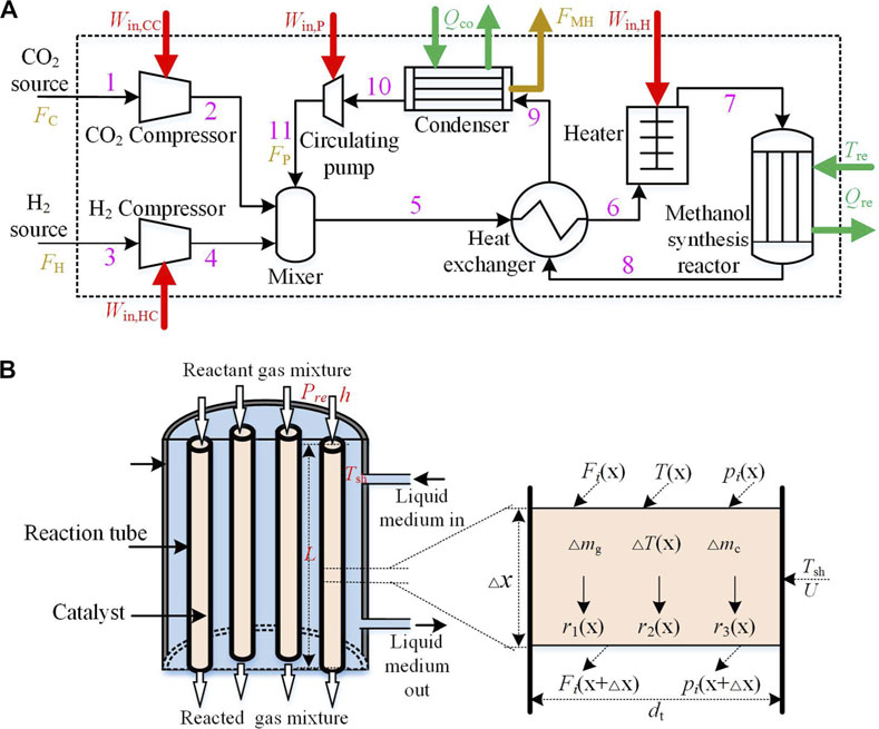
FIGURE 1. (A) The schematic diagram of the CDHM system; (B) The schematic diagram of methanol synthesis reactor.
The MSR is the core component of the CDHM system, and its schematic diagram is illustrated in Figure 1B. The MSR is installed with reaction tubes which are packed with the catalyst. The catalytic reactions occur in the reaction tubes. Besides, the liquid medium with strong heat transferability is used in the MSR to surround the reaction tubes. Thus, heat released during the methanol synthesis reaction is taken away by the liquid medium. Because the heat exchange between the liquid medium and reaction tubes is intense and rapid, the reaction temperature in the tubes is considered to be equal to the liquid medium temperature. Besides, the reactions in the MSR are influenced by the reaction temperature and other reaction conditions such as pressure and space velocity.
In the CDHM system, the reactants are hydrogen and carbon dioxide, while the end products are methanol and water. In order for the CDHM system to operate normally, external energy mainly input power and cold energy should be input. Specifically, input power is required in the H2 compressor, CO2 compressor, and circulating pump to compress the gases, as well as in the heater to heat the mixture gas. Cold energy in the condenser and MSR is used for heat dissipation.
Energy and Exergy Analysis Modeling
In the modeling process, energy analysis modeling is conducted firstly to obtain the key parameters such as mass flow, temperature, and pressure which are vital for the exergy analysis. Then, the exergy analysis models to obtain all kinds of exergies in the system are established, which could reveal the real energy change in the system.
Energy Analysis Modeling
The energy analysis modeling of the CDHM system and each component in it are based on the first law of thermodynamics (Xiong et al., 2019; Rafiee, 2020). For an open system, energy can be transferred in and out of the system with streams of matter, heat transfer, and work (Nimkar et al., 2017). In this paper, the changes in kinetic and potential energies are not considered. Thus, the energy balance in steady-state conditions is given as follows:
where ṁ is the mass flow rate; the subscripts “in” and “out” signify the flow in and out of the system, respectively; h is the specific enthalpy whose expression is given in Eq. 5;
where u, p, and V are the internal energy, pressure, and volume, respectively. It has to be noted that the energy loss due to pressure drop in each component is eventually converted into internal energy of the airflow. Therefore, the detailed analysis of pressure drop and internal energy which is not the main concern can be avoided when the variable of enthalpy is adopted in modeling.
In order to facilitate analysis of the energy balance in the MSR, the reaction tube which is the real energy change module in the MSR is divided into infinite numbers of elements along its axial direction. The element analysis schematic diagram is shown in Figure 1B. A homogeneous model shown in Eq. 7 is established to describe the steady-state energy balance of the element:
where cg and ∆mg are the reactant gas–specific heat and mass in the element, respectively; cc and ∆mc are the catalyst-specific heat and mass in the element, respectively; T(x) and ∆T(x) are the temperature of the reactant gas and its change at x point, respectively; ∆A is the superficial area of the element; U is the heat transfer coefficient between the liquid medium and the reaction tube wall; Tsh is the temperature of the liquid medium; r1(x), r2(x), and r3(x) are the reaction ratios of the three reactions described in Eqs. 1–3, respectively, whose kinetic models refer to that proposed by Seidel et al. (2018); ∆Hr1, ∆Hr2, and ∆Hr3 are the reaction enthalpy of the three reactions, respectively; ρg is the reaction density; and ∆p(x) is the pressure drop of the element at X point which is described as
where ɛc is the porosity of the catalyst; Re and v are the Reynolds number and velocity of the reactant gas, respectively; and dt is the inner diameter.
The synthesized methanol along the axial direction of the reaction tube is gradually accumulated. The molar flow change of each component in the gas mixture between two adjacent elements is given as
where i is used to represent the component in the gas mixture which includes carbon dioxide, carbon monoxide, hydrogen, methanol, and water stream; Fi(x+∆x) and Fi(x) are the molars of each component at x point and x+∆x point, respectively; and ri′(x) is the reaction ratio of each component.
Exergy Analysis Modeling
The exergy concept is developed based on the second law of thermodynamics, reflecting that all transformations are irreversible in nature and generate entropy. Exergy can be transferred into and removed from a system through three means which are mass flow, heat transfer, and work (Soohret et al., 2015). For an open system, the exergy balance equation to describe the exergy flow is given as
where ex is the exergy of per mass, ĖxQ is the exergy associated with heat transfer, and Ėxd is the exergy destruction.
Exergy whose expression is given in Eq. 11 generally consists of physical, chemical, kinetic, and potential components. In the CDHM system, the kinetic exergy eKN and potential exergy ePT are negligible. The physical exergy ePH and chemical exergy eCK are expressed in Eqs. 12, 13, respectively:
where T and T0 are the temperatures of current condition and reference condition, respectively; yi and
The exergy associated with heat transfer is described as follows:
The exergy efficiency of the CDHM system is given as follows:
According to the mass balance, energy balance, and exergy balance, the equations of each component in the system can be seen in Table 1.

TABLE 1. Mass, energy, and exergy balance of each component.
Results and Discussions
Operating Parameters and Calculation Cases’ Arrangement
Specifications of the MSR and the chosen commercial Cu/ZnO/Al2O3 catalyst are described on the left side of Table 2. Working parameters such as temperature and operating pressure are specified on the right side of Table 2 and function as the initial condition for the cases’ arrangement of exergy analysis. According to the study of Seidel, the reasonable reaction condition is 5–10 MPa for pressure, 473.15–573.15 K for temperature, and 2,500–4,000 h−1 for space velocity (Seidel et al., 2018). Thus, the reaction pressure, temperature, and space velocity are arranged in the limited ranges to explore the effects of parameters on the exergy performance of the CDHM system. Specifically, the cases of 5, 6, 7, and 8 MPa are arranged to demonstrate the reaction pressure influence on the exergy performance; the cases of 483.15, 503.15, 523.15, and 543.15 K are set to show the reaction temperature influence; and the cases of 2,800, 3,200, 3,600, and 4000 h−1 are organized to illustrate the space velocity effect on the exergy performance.
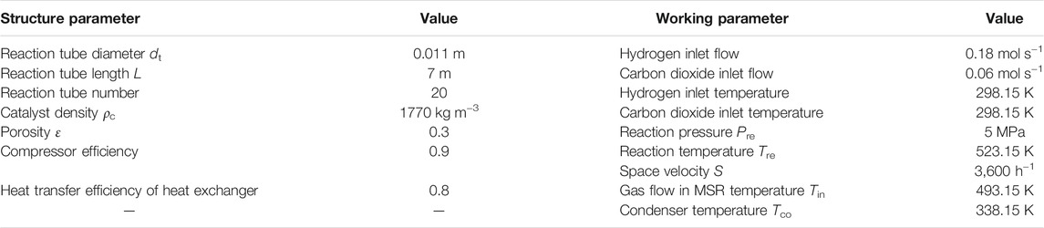
TABLE 2. Specification and working parameters of the CDHM system.
All the established models in this paper are solved in MATLAB. It has to be noted that the uncertainty of the calculation results mainly comes from the selection of the length of the reaction tube element dx in Eqs. 7–9. According to the conclusion in the study of Bathe et al. (1972), the systematic error will be less than 1% when the chosen calculation step is not greater than 0.02 times the calculation cycle. In order to reduce the uncertainty of the calculation results, the calculation step in this paper is selected to be 0.001 times the reaction tube length.
Exergy Performance Under Different Reaction Pressures
The flows of eliminated reactants, circulating gas, and synthetic methanol are shown in Figure 2A. It can be found that the flows of eliminated hydrogen and carbon dioxide, that is, FH and FC, increase at the same rate of 13.3% when the reaction pressure increases from 5 to 8 MPa. As the eliminated reactants are eventually synthesized into methanol, the flow of synthetic methanol FMH is also observed to increase by 13.3%, while the flow of circulating gas FP decreases by 9.02%. The reason is that the increase of reaction pressure contributes to the increase of methanol synthesis rate, which eventually leads to the increases of FC, FH, and FMH. The flow of circulating gas FP, determined by the flow of unreacted gas mixture flowing out of the MSR, consequently declines with the increase of reaction pressure. As shown in Figure 2B, the hydrogen compressor and the heater consume the most amount of input power in the system, and their values are 1955.7 and 1713.8 W at 5 MPa, respectively. In contrast, the circulating pump requires the least amount of input power with a value of 355.2 W. Besides, almost all the input power increases when the reaction pressure is increased. Specifically, the input power of hydrogen and carbon dioxide compressors, that is, Win,HC and Win,CC, sees the largest rise with the same value of 26.2%, which is mainly due to the increase of flows of hydrogen and carbon dioxide. The increase of input power for the heater Win,H is not significant because the flow of gas mixture in the heater, namely, the summation of FC, FH, and FP, changes little. The results show that more input power about 14.42% is required for the system with the increase in reaction pressure. As shown in Figure 2C, the cold energy consumed in the MSR
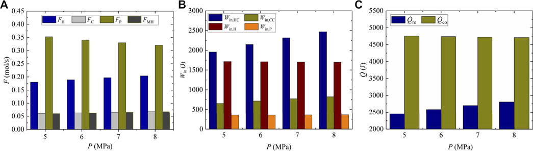
FIGURE 2. Molar flow and input energy under different reaction pressures; (A) molar flow; (B) Input powers; (C) cold energy consumption.
The exergy destruction in the CDHM system is specified in Table 3. It can be easily found that the exergy destruction in the heater, heat exchanger hot end, and cold end decreases when the reaction pressure increases from 5 to 8 MPa, while the exergy destruction in other components all increases. As a result, the total exergy destruction of the CDHM system increases from 12,983.05 to 14,845.05 W at the rate of 14.34%. Figure 3 shows the distribution proportions of the exergy destruction for each component in the CDHM system. It should be pointed out that the MSR has the biggest exergy destruction compared with other components. For example, it accounts for about 80.08% of the total value at 5 MPa. The exergy destruction in the MSR is caused by the chemical reaction process and irreversible heat exchange between the reaction tubes and the liquid medium. Besides, the exergy destruction proportions of the heater and the heat exchanger hot end, which are 8.14 and 3.68%, respectively, are the second and third biggest exergy destruction proportions in the system. The exergy destruction of those two components is mainly contributed by the irreversible heat transfer. The exergy destruction proportions in other components are relatively small. Because the increase rates of exergy destructions in the three components as shown in Table 3 are all smaller than that of the total system, the exergy destruction proportions of the three components shown in Figure 3 all slightly decrease with the increase of reaction pressure. Thus, the summation of exergy destruction proportions of the three components decreases from 91.9 to 90.19%. Moreover, the total exergy destruction of the CDHM system can be decreased significantly through reducing the three biggest exergy destructions because their summation accounts for the vast majority of the total exergy destruction, which is conducive to the improvement of exergy efficiency for the CDHM system.
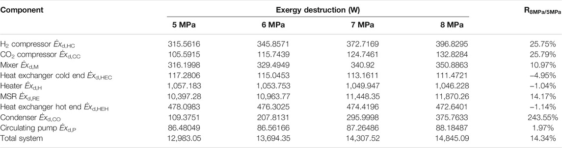
TABLE 3. Exergy destructions in the CDHM system under different reaction pressures.
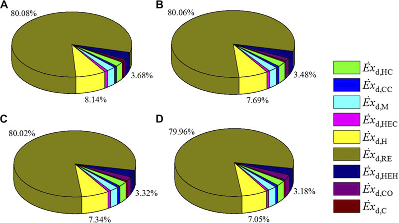
FIGURE 3. Distribution proportion of exergy destruction for each component under different reaction pressures, (A) 5 MPa, (B) 6 MPa, (C) 7 MPa, (D) 8 MPa.
The total input power, cold energy, and exergy destruction per molar synthetic methanol are shown in Figure 4. Along with the increase of the total input power, when more methanol is produced, the total input power per molar synthetic methanol Win/FMH increases by 1.03% from 77,916.685 to 78,716.314 W mol−1 with the reaction pressure changing from 5 to 8 MPa. This is because the increase rate of the total input power is higher than that of methanol synthesis when the pressure increases. Meanwhile, the total consumed cold energy per molar synthetic methanol
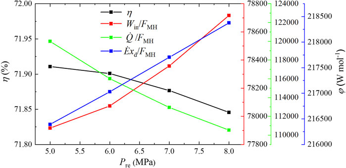
FIGURE 4. Input power, cold energy, and exergy destruction per molar synthetic methanol and exergy efficiency under different reaction pressures.
Exergy Performance Under Different Reaction Temperatures
As shown in Figure 5A, the flow of eliminated hydrogen FH increases from 0.16332 to 0.1953 mol s−1 when the reaction temperature rises from 483.15 to 543.15 K. Meanwhile, both the eliminated carbon dioxide flow FC and the synthetic methanol flow FMH rise from 0.05444 to 0.0651 mol s−1. Besides, FH, FC, and FMH see the same increase rate of 19.58%, while the flow of circulating gas FP drops from 0.4833 to 0.4620 mol s−1 when the reaction temperature increases from 483.15 to 543.15 K. The increases of FMH, FH, and FC can be explained by the increasing reaction temperature, which accelerates the methanol synthesis rate and causes the increase in the amount of eliminated reactants. Besides, the increase of methanol synthesis rate leads to the decrease in the flow of gas mixture flowing out of the MSR, which contributes to the decrease of FP. The input power under different reaction temperatures, as shown in Figure 5B, grows with the increase of reaction temperature. Specifically, the input power of hydrogen compressor Win,HC increases obviously from 1774.49 to 2,121.85 W when the reaction temperature increases from 483.15 to 543.15 K, the input power of carbon dioxide compressor Win,CC goes up slightly from 591.50 to 707.28 W, while the increase of input power for the heater and circulating pump, that is, Win,H and Win,P, is less noticeable. The main reason lies in the increase in the input power of hydrogen and carbon dioxide compressors with larger eliminated hydrogen and carbon dioxide flows. Thus, the total input power increases by 11.99% from 4,399.69 to 4,927.31 W. As shown in Figure 5C, the cold energy consumed in the condenser sees a slight slip from 4,866.87 to 4,659.01 W when the reaction temperature increases from 483.15 to 543.15 K, while the cold energy consumed in the MSR increases from 2,160.12 to 2,702.02 W. Consequently, there is a 4.75% increase in total cold energy consumption from 7,026.99 to 7,361.04 W. Because higher reaction temperature leads to the increases of methanol synthesis and corresponding reaction heat release, the required cold energy to dissipate the reaction heat in the MSR increases. Due to more gas mixture flow through the cold end of the heat exchanger, more heat transfers from the hot end to the cold end of the heat exchanger; thus, less cold energy is required in the condenser for cooling the gas mixture flowing in from the hot end of the heat exchanger.
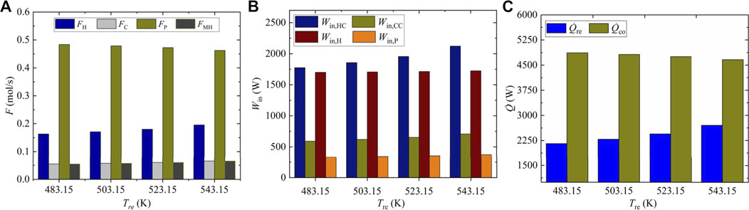
FIGURE 5. Molar flow and input energies under different reaction temperatures, (A) molar flow, (B) Input power, (C) cold energy consumption.
Exergy destruction of each component in the CDHM system under different reaction temperatures is listed in Table 4. It can be easily obtained that the three biggest components of exergy destruction in the system are the MSR, heater, and heat exchanger hot end, whose exergy destruction values are 9,443.857, 1,047.168, and 485.938 W at 483.15 K, respectively. Exergy destruction in other components is relatively small. Besides, exergy destruction in each component goes up with the increase of reaction temperature with the exception of both the hot end and the cold end of the heat exchanger, which results in the increase in the total exergy destruction of the CDHM system from 11,855.08 to 14,011.34 W at the rate of 18.19%. As shown in Figure 6, it can be obviously found that the three biggest exergy destruction proportions also take place in the MSR, heater, and heat exchanger hot end, just like that in Figure 3. Besides, the exergy destruction proportion of the MSR increases from 79.66 to 80.37% when the reaction temperature rises from 483.15 to 543.15 K, while the exergy destruction proportions of the heater and heat exchanger hot end decrease from 8.83 to 7.6% and from 4.1 to 3.37%, respectively. As a result, the summation of exergy destruction proportions of the three components decreases from 92.59 to 91.34%. Combining Table 4 and Figure 6, it can be found that because the increase rate of exergy destruction in the MSR, that is, 19.24%, is bigger than that of the total system which is 18.19%, the exergy destruction proportion of the MSR increases. Since the increase rate of exergy destruction in the heater, that is, 1.73%, is smaller than that of the total system, the exergy destruction proportion of the heater decreases. The decrease of the exergy destruction proportion of the heat exchanger hot end mainly results from the decrease in its exergy destruction.

TABLE 4. Exergy destructions in the CDHM system under different reaction temperatures.
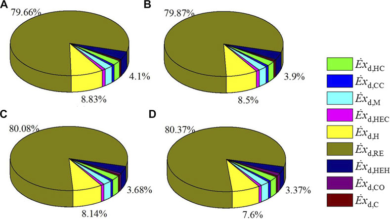
FIGURE 6. Distribution proportion of exergy destruction for each components under different reaction temperatures, (A) 483.15K, (B) 503.15K, (C) 523.15K, (D) 543.15K.
As shown in Figure 7, the total input power, cold energy consumption, and exergy destruction per molar synthetic methanol all decrease when the reaction temperature increases from 483.15 to 543.15 K. Specifically, the total input power per molar synthetic methanol Win/FMH drops by 6.36% from 80,827.331 to 75,689.231 W mol−1, the total cold energy consumption per molar synthetic methanol
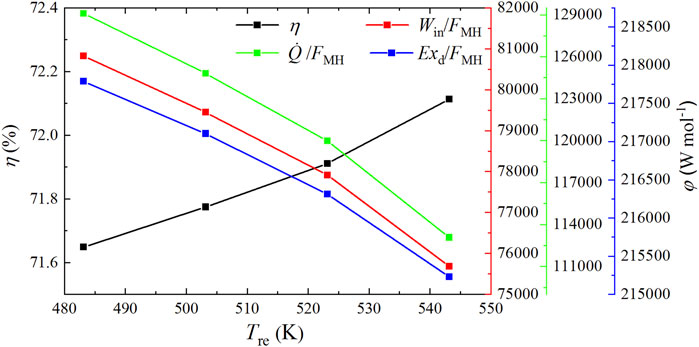
FIGURE 7. Input power, cold energy, and exergy destruction per molar synthetic methanol and exergy efficiency under different reaction temperatures.
Exergy Performance Under Different Reaction Space Velocities
As shown in Figure 8A, when the space velocity rises from 2,800 to 4000 h−1, the flow of eliminated hydrogen FH increases from 0.1494 to 0.1949 mol s−1, and the flow of both eliminated carbon dioxide FC and synthetic methanol FMH grows from 0.0497 to 0.0649 mol s−1 with the same rate of 30.58%. Meanwhile, the flow of circulating gas
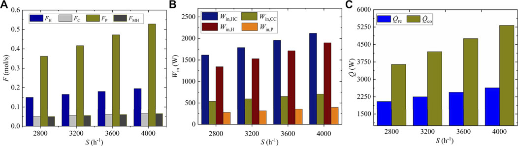
FIGURE 8. Molar flow and input energies under different space velocities, (A) molar flow, (B) Input power, (C) cold energy consumption.
Exergy destruction of each component in the CDHM system at different space velocities is listed in Table 5. It clearly shows that exergy destruction in each component increases with higher space velocity with the exception of visible decrease in the heat exchanger cold end and the condenser. Thus, the total exergy destruction in the CDHM system increases by 30.38% from 10,768.84 to 14,041.08 W when the reaction space velocity increases from 2,800 to 4000 h−1. Combining Figure 8A and Table 5, it can be obtained that the increase of exergy destruction in each component is mainly caused by the increased flow of the gas mixture in it. As shown in Figure 9, the three biggest exergy destruction proportions take place in the MSR, heater, and heat exchanger hot end, respectively, and they are all positively correlated with the space velocity. Specifically, the exergy destruction proportion of the MSR increases from 79.8 to 80.18% when the reaction space velocity rises from 2,800 to 4000 h−1, and that of the heater and the heat exchanger hot end increases from 7.7 to 8.33% and from 3.12 to 3.92%, respectively. This can be explained by the higher increase rate of exergy destruction in the MSR, heater, and heat exchanger hot end than that of the total system. The increase of exergy destruction proportions of the three components causes a rise in their summation from 90.62 to 92.43%.
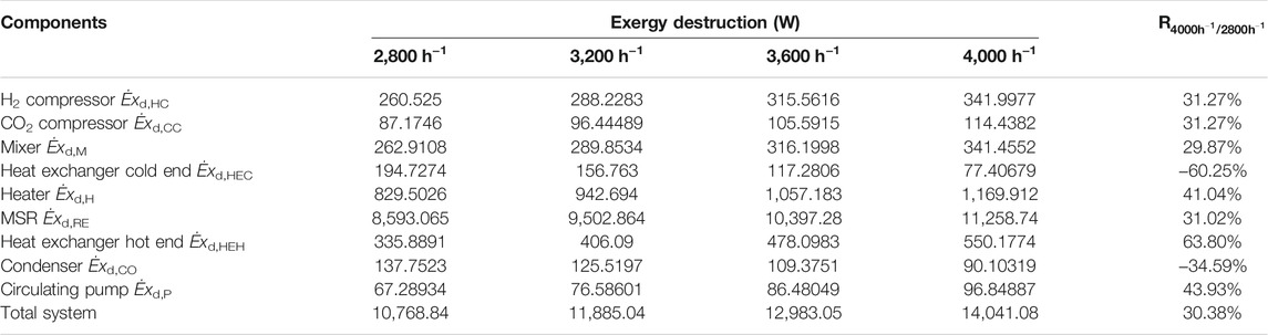
TABLE 5. Exergy destruction in the CDHM system under different space velocities.
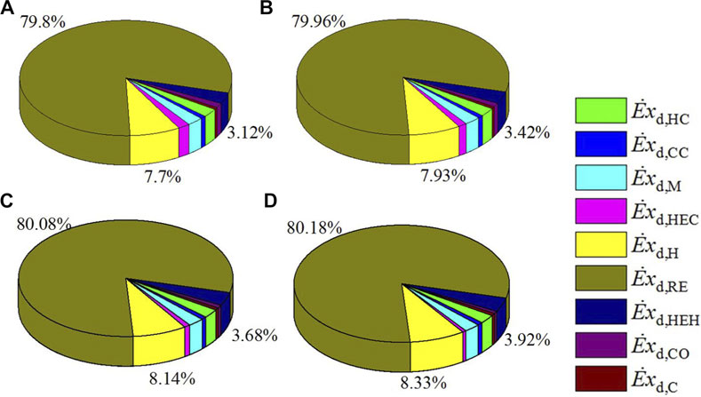
FIGURE 9. Distribution proportion of exergy destruction for each component under different space velocities, (A) 2800h−1, (B) 3200h−1, (C) 3600 h−1, (D) 4000h−1.
As shown in Figure 10, both the total input power and the cold energy per molar synthetic methanol increase linearly with increased space velocity. Specifically, Win/FMH increases by 3.96% from 75,907.60 to 78,914.64 W mol−1 when the space velocity increases from 2,800 to 4000 h−1,
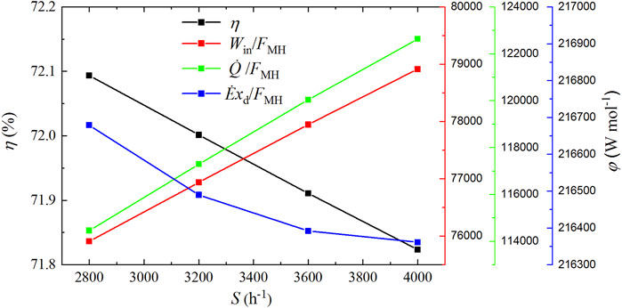
FIGURE 10. Input power, cold energy, and exergy destruction per molar synthetic methanol and exergy efficiency under different space velocities.
Conclusion
It is important for the system of carbon dioxide hydrogenation to methanol (CDHM) in the habitable confined space (HCS) to operate with high energy efficiency to reduce unnecessary external energy input and internal energy loss. In this paper, exergy analysis is adopted to present the energy utilization quality for the purpose of exergy efficiency improvement. The models of energy analysis and exergy analysis for each component in the CDHM system are established. As the energy conversion process in the CDHM system is dramatically influenced by three reaction parameters: pressure, temperature, and space velocity, a parametric study on exergetic performance for the CDHM system is conducted to find the favorable working parameters that consume low external energy per gas elimination under the constraint of limited external energy input. The model’s calculation process is conducted in MATLAB, in which the three reaction parameters range from 5 to 8 MPa, from 483.15 to 543.15 K, and from 2,800 to 4000 h−1, respectively. Besides, the length of the reaction tube element in the models is selected as 0.001 times the reaction tube length to reduce the uncertainty of the model’s calculation results. Based on the calculation results, the main conclusions are summarized as follows.
A rise in pressure will obtain the increases in the elimination of hydrogen and carbon dioxide, total input power, cold energy consumption, and exergy destruction by 13.3, 14.42, 4.33, and 14.34%, respectively; as a result, the total input power and exergy destruction per molar synthetic methanol increase by 1.03 and 0.92%, respectively, and the total cold energy consumption per molar synthetic methanol declines by 7.88%, which eventually leads to a reduction of the exergy efficiency by 0.06% from 71.91 to 71.85%. The elimination of hydrogen and carbon dioxide, total input power, cold energy consumption, and exergy destruction increase by 19.58, 11.99, 4.75, and 18.19%, respectively, when the reaction temperature goes up, while the total input power, cold energy consumption, and exergy destruction per molar synthetic methanol all obtain the decreases by 6.36, 12.4, and 1.17%, respectively, followed by the increase of the exergy efficiency by 0.46% from 71.65 to 72.11%. Increased space velocity will make elimination of hydrogen and carbon dioxide, total input power, cold energy consumption, and exergy destruction increase by 30.58, 35.75, 39.9, and 30.38%, respectively, which results in 3.96 and 7.14% increase in the total input power and cold energy consumption per molar synthetic methanol, respectively, and 0.15% decrease in exergy destruction per molar synthetic methanol; as a consequence, the exergy efficiency is reduced by 0.27% from 72.09 to 71.82%. Relatively low pressure, high temperature, and low space velocity constitute best conditions for realizing high exergy efficiency. Besides, exergy efficiency also can be significantly improved by reducing the three biggest exergy destructions in the methanol synthesis reactor, heater, and heat exchanger hot end because the summation of the three biggest exergy destructions accounts for more than 90% of the total exergy destruction in the CDHM system.
Carbon dioxide and hydrogen should be collected before being fed into the CDHM system during the atmospheric balance control process in the HCS, while their collection process is not considered in the CDHM system process in this paper. In order to make the energy consumption results more comprehensive, the energy consumption in the collection processes of carbon dioxide and hydrogen should be analyzed in the future work.
Data Availability Statement
The original contributions presented in the study are included in the Article/Supplementary Material, and further inquiries can be directed to the corresponding author.
Author Contributions
KX conceptualized the research idea and wrote the original draft. KX and YY performed the methodology. KX and YC involved in formal analysis. XL reviewed and edited the paper. All authors read and agreed to the published version of the manuscript.
Conflict of Interest
The authors declare that the research was conducted in the absence of any commercial or financial relationships that could be construed as a potential conflict of interest.
Publisher’s Note
All claims expressed in this article are solely those of the authors and do not necessarily represent those of their affiliated organizations, or those of the publisher, the editors, and the reviewers. Any product that may be evaluated in this article, or claim that may be made by its manufacturer, is not guaranteed or endorsed by the publisher.
Supplementary Material
The Supplementary Material for this article can be found online at: https://www.frontiersin.org/articles/10.3389/fenrg.2021.725376/full#supplementary-material
References
Al-Abbas, A. H., Mohammed, A. A., and Hassoon, A. S. (2020). Exergy Analysis of Shell and Helical Coil Heat Exchanger and Design Optimization. Heat Mass. Transfer 57 (5), 797–806. doi:10.1007/s00231-020-02993-9
Ansari, K. A., Azhar, M., and Altamush Siddiqui, M. (2021). Exergy Analysis of Single-Effect Vapor Absorption System Using Design Parameters. J. Energ. Resour. Technol. 143 (6), 062105. doi:10.1115/1.4048594
Blumberg, T., Morosuk, T., and Tsatsaronis, G. (2019). CO2-Utilization in the Synthesis of Methanol: Potential Analysis and Exergetic Assessment. Energy 175, 730–744. doi:10.1016/j.energy.2019.03.107
Blumberg, T., Morosuk, T., and Tsatsaronis, G. (2017). Exergy-Based Evaluation of Methanol Production from Natural Gas with CO2 Utilization. Energy 141, 2528–2539. doi:10.1016/j.energy.2017.06.140
Carey, R., Gomezplata, A., and Sarich, A. (1983). An Overview into Submarine CO2 Scrubber Development. Ocean Eng. 10, 227–233. doi:10.1016/0029-8018(83)90010-0
Cheng, L.-H., Zhang, L., Chen, H.-L., and Gao, C.-J. (2008). Hollow Fiber Contained Hydrogel-CA Membrane Contactor for Carbon Dioxide Removal from the Enclosed Spaces. J. Membr. Sci. 324, 33–43. doi:10.1016/j.memsci.2008.06.059
Cho, Y. M., Yang, Y. M., Park, D. S., Kwon, S. B., Jung, W. S., and Lee, J. Y. (2013). Study on CO2 Adsorption on LiOH-Modified Al2O3. Appl. Mech. Mater. 284-287, 342–346. doi:10.4028/www.scientific.net/amm.284-287.342
Crivellari, A., Cozzani, V., and Dincer, I. (2019). Exergetic and Exergoeconomic Analyses of Novel Methanol Synthesis Processes Driven by Offshore Renewable Energies. Energy 187, 115947. doi:10.1016/j.energy.2019.115947
Do, T. N., and Kim, J. (2019). Process Development and Techno-Economic Evaluation of Methanol Production by Direct CO2 Hydrogenation Using Solar-Thermal Energy. J. CO2 Utilization 33, 461–472. doi:10.1016/j.jcou.2019.07.003
Jadhav, S. G., Vaidya, P. D., Bhanage, B. M., and Joshi, J. B. (2014). Catalytic Carbon Dioxide Hydrogenation to Methanol: A Review of Recent Studies. Chem. Eng. Res. Des. 92, 2557–2567. doi:10.1016/j.cherd.2014.03.005
Kiss, A. A., Pragt, J. J., Vos, H. J., Bargeman, G., and de Groot, M. T. (2016). Novel Efficient Process for Methanol Synthesis by CO 2 Hydrogenation. Chem. Eng. J. 284, 260–269. doi:10.1016/j.cej.2015.08.101
Lewis, J. F., Granahan, J., Russell, M., and Lumpkin, J. (2005). International Space Station (ISS) Environmental Controls & Amp; Life Support System (ECLSS) Manual Oxygen Management. SAE. Technical Paper 2005-01-2895. doi:10.4271/2005-01-2895
Li, J., Ai, S. K., and Zhou, K. H. (1999). An Experimental Study of the Sabatier CO2 Reduction Subsystem for Space Station. Space Med. Eng. 12, 121–124.
Muhammad, H. A., Lee, B., Cho, J., Rehman, Z., Choi, B., Cho, J., et al. (2021). Application of Advanced Exergy Analysis for Optimizing the Design of Carbon Dioxide Pressurization System. Energy 228, 120580. doi:10.1016/j.energy.2021.120580
Nimkar, S. C., Mewada, R. K., and Rosen, M. A. (2017). Exergy and Exergoeconomic Analyses of Thermally Coupled Reactors for Methanol Synthesis. Int. J. Hydrogen Energ. 42 (47), 28113–28127. doi:10.1016/j.ijhydene.2017.09.055
Rafiee, A. (2020). Modelling and Optimization of Methanol Synthesis from Hydrogen and CO2. J. Environ. Chem. Eng. 8 (5), 104314. doi:10.1016/j.jece.2020.104314
Razi, F., Dincer, I., and Gabriel, K. (2020). Energy and Exergy Analyses of a New Integrated Thermochemical Copper-Chlorine Cycle for Hydrogen Production. Energy 205, 117985. doi:10.1016/j.energy.2020.117985
Russell, J. F., and Klaus, D. M. (2007). Maintenance, Reliability and Policies for Orbital Space Station Life Support Systems. Reliability Eng. Syst. Saf. 92, 808–820. doi:10.1016/j.ress.2006.04.020
Schmitt, E., Norman, T., Roy, R., Mittelsteadt, C., Murach, B., and Ogle, K. (2011). Development Testing of High-Pressure Cathode Feed Water Electrolysis Cell Stacks for Microgravity Environments. Technical Paper AIAA 2011-5058-911. doi:10.2514/6.2011-5058
Seidel, C., Jörke, A., Vollbrecht, B., Seidel-Morgenstern, A., and Kienle, A. (2018). Kinetic Modeling of Methanol Synthesis from Renewable Resources. Chem. Eng. Sci. 175, 130–138. doi:10.1016/j.ces.2017.09.043
Şöhret, Y., Dinç, A., and Karakoç, T. H. (2015). Exergy Analysis of a Turbofan Engine for an Unmanned Aerial Vehicle during a Surveillance mission. Energy 93, 716–729. doi:10.1016/j.energy.2015.09.081
Voloshchuk, V., Gullo, P., and Sereda, V. (2020). Advanced Exergy-Based Performance Enhancement of Heat Pump Space Heating System. Energy 205, 117953. doi:10.1016/j.energy.2020.117953
Xie, S., Zhang, W., Lan, X., and Lin, H. (2020). CO 2 Reduction to Methanol in the Liquid Phase: A Review. ChemSusChem 13 (23), 6141–6159. doi:10.1002/cssc.202002087
Xiong, K., Li, Y., Li, Y.-Z., Wang, J.-X., and Mao, Y. (2019). Numerical Investigation on the thermal Performance of Nanofluid-Based Cooling System for Synchronous Generators. Entropy 21 (4), 420. doi:10.3390/e21040420
Younas, M., Loong Kong, L., Bashir, M. J. K., Nadeem, H., Shehzad, A., and Sethupathi, S. (2016). Recent Advancements, Fundamental Challenges, and Opportunities in Catalytic Methanation of CO2. Energy Fuels 30, 8815–8831. doi:10.1021/acs.energyfuels.6b01723
Zhang, W., Liu, H., Sun, C., Drage, T. C., and Snape, C. E. (2014). Capturing CO2 from Ambient Air Using a Polyethyleneimine-Silica Adsorbent in Fluidized Beds. Chem. Eng. Sci. 116, 306–316. doi:10.1016/j.ces.2014.05.018
Keywords: energy efficiency, exergy analysis, CO2 hydrogenation, methanol synthesis, exergy destruction
Citation: Xiong K, Yin Y-L, Cao Y and Liu X-T (2021) Exergy Efficiency Promotion for the System of CO2 Hydrogenation to Methanol in Habitable Confined Space. Front. Energy Res. 9:725376. doi: 10.3389/fenrg.2021.725376
Received: 15 June 2021; Accepted: 11 August 2021;
Published: 09 September 2021.
Edited by:
Guven Gonca, Yıldız Technical University, TurkeyReviewed by:
Audai Hussein Al-Abbas, Al-Furat Al-Awsat Technical University, IraqGörkem Kökkülünk, Yıldız Technical University, Turkey
Hasan Kayhan Kayadelen, Yıldız Technical University, Turkey
Copyright © 2021 Xiong, Yin, Cao and Liu. This is an open-access article distributed under the terms of the Creative Commons Attribution License (CC BY). The use, distribution or reproduction in other forums is permitted, provided the original author(s) and the copyright owner(s) are credited and that the original publication in this journal is cited, in accordance with accepted academic practice. No use, distribution or reproduction is permitted which does not comply with these terms.
*Correspondence: Kai Xiong, eGlvbmdfa0AxMjYuY29t