 Saif Al Omairi
 Marya Al Balushi
 Kenneth E. Okedu
- 1Department of Electrical and Communication Engineering, National University of Science and Technology, Muscat, Oman
- 2Department of Electrical and Electronic Engineering, Nisantasi University, Istanbul, Turkey
This article presents an overview of the transmission system and protection schemes employed in the national power grid of Oman. The technical design requirements considering the percentage of allowable limits for the different transmission voltage levels in the power grid of Oman were considered based on the electrical standards and grid codes of Oman. Also, the protection and fault requirements based on relay settings and backup protection were some of the factors considered in this study. More so, the power flow, peak, and off-peak voltage profiles of the main interconnection and Dhofar transmission systems were analyzed in detail, considering projections for 2021 and 2025, respectively, for effective energy management and smart grid operations. The current protection equipment of the power grid of Oman was evaluated, and some improvement schemes were proposed considering the implementation of the new technology for smart grid operation. The continuous investment in the transmission system of the Oman power grid and the use of updated protection technology would lead to the enhancement of the performance of the Oman transmission system to reach a high-level power transmission availability.
Introduction
The electricity transmission system is the essential part of the electricity network because it is the main channel between the generation plants and the distribution networks. However, a complete attention should be taken by the designers of the entire power grids, generation plants, the transmission system, and the distribution system, when the power protection schemes are designed. The main role of the protection scheme is to maintain high power availability with safe operation in a cost-effective way. This means that the protection systems should isolate the faulty sections, minimizing the rapier cost and maintaining the full life time of the equipment in the power grid.
The Oman electricity transmission system with voltage levels of 33 kV, 132 kV, 220 kV, and 400 kV represents the effective channel between the power producers and the distribution companies (Abdalla et al., 2009; Oman Electricity Transmission Company (OETC), 2011; Abdalla et al., 2012a). This indicates the high importance of the protection schemes in Oman Electricity and Transmission Company (OETC) networks. However, all electricity companies in Oman follow the Oman Grid Code and Oman Electrical standards (Authority for Electricity, 2016; Oman Electricity and Tran, 2020a), along with several policies and agreements that guarantee the effective planning, designing, and operation of the protection schemes of the electricity network.
The last published number of the population in the Sultanate of Oman is 5,175,047 (Author Anonymous, 2019), and this number keeps increasing by the day. As a result, this will lead to more demand of electricity, thus putting pressure on the national power grid. Therefore, it is imperative for the electricity sector in Oman to keep abreast with developments and trends in modern power grids in a bid to ensuring regular supply and security of electrical power, without interruptions. One way of doing this is by considering stability protection as the main target in order to prevent the inadmissible events of power interruptions and blackouts in the power grid.
Considering the Oman neighboring countries such as Saudi Arabia, with a power transmission network with an extended area of 2149690 sq.km, serving a population of 35,435,144 with 1,124 substations and 84,787 km of the transmission line, it is clear that the Oman transmission network with 83 grid stations is a small transmission network comparatively (Trading Economics, 2021; Saudi Electricity Company, 2020; Worldometer, 2021. In addition, the Oman power transmission system cannot be compared to an advanced power transmission network such as the China power grid, with power transmission in the range of 800 to 3,000 km in length, due to the significant differences in geographical and demographical nature along with economic potentials (Shu and Chen, 2018). The diversity of the geographic nature of Oman including the long costal area and the wide area of desert, mountains, and valleys forced the OETC to adopt a power transmission system that could be reliable in order to suit the geographical nature of Oman.
This work provides extensive analysis of the Oman transmission system and the adopted standards, codes, and policies that characterized the protection scheme in the Oman transmission scheme. In addition, this article shows the penetration of the new technology in the grid such as the load dispatch center application in controlling the grid operation. Analyzing the Oman power transmission network according to the structure, demand, adopted codes, and standards and the penetration of smart grids provides a clear and efficient understanding of the network nature, which is an essential task to overcome the challenges and enhance the network performance as well as provide a practical tool for future extension and increase in renewable energy penetration. Hence, this study methodology starts with an introduction of the Oman transmission system, followed by extensive details of the transmission network standards and technical protection requirements. Moreover, the power demand data were analyzed, as well as the supply security. Recent technologies used in Oman power grid were discussed along with the new projects that will enhance the penetration of renewable energy and the use of smart grid technologies. These detailed analyses enriched with smart grid applications in the Oman power grid show the increased progress of the Oman electrical sector to invest in smart grid applications. In addition, the data shown in this article provide a helpful tool to indicate the challenges in the Oman grid transmission system and its protection schemes.
As part of the development plans, a new 400 kV interconnection between the Main Interconnected System (MIS), Petroleum Development Company of Oman (PDO), Dhofar, and the region of Duqm is presented in this article, in line with the various pieces of protection equipment in the power grid of Oman. The ideas presented in this article have a positive impact on the existing power system because it will lead to fuel saving, reduction in operating costs, and improvement in the grid security and allow more access to renewable energy areas, which will lead to improvement in energy management and smart grid operations in the Sultanate of Oman. The other sections of this article would cover the technical design of protection schemes, the supply security and power flow, the various pieces of protection equipment, and improvement of the current protection schemes in the power grid of Oman.
Technical Design Requirements
There are several technical requirements that have been adapted in the design of Oman national power grids, including the MIS and Dhofar power systems. First and foremost, there was improvement in the transmission of bulk power from the generation plants to the distribution substation to reach the security level of supply requirements. In addition, there was a need to reduce the load on the loaded grid stations in order to enhance the load transferred to existing or new grid stations. Moreover, there was an increase in the transmission system capacity to improve the transmission system performance in order to meet the future demand requirements. The OETC also adapted strategic planning concepts of developing a backbone of 400kV systems to achieve the technical requirement goals in improving the performance of the transmission system. The 400 kV systems of OETC are as follows (Oman Electricity Transmis, 2020):
• Line between the Jahloot grid station and Sur power plant
• Line between the Sur power station and new Izki grid station
• Line between the Ibri grid station and new Izki grid station
• 400/220 kV Ibri grid station
• Line between the Sohar Free Zone grid station and Shinas grid station
• Line between the Sohar Free Zone grid station and Seh Al Makaram (SIS)
• Line between the Sohar Free Zone grid station and Mahadha grid station
• Line between Sohar-3 IPP and the Sohar Free Zone grid station
• Loop-in loop-out (LILO) connection from Sur to the new Izki line
• LILO connection from Sur to the New Izki 400 kV line at the Qabel grid station through a 400/132 kV grid station and the 400 kV connection line to the Ibri IPP power plant
• Line between the new Izki grid station and Misfah grid station
According to the Main Interconnection Transmission System (MITS) strategic plan, the number of 400 kV grid stations in the system will be 19 grid stations by 2025, with a total capacity of 21,500 MVA, as shown in Figure 1 (Oman Electricity and Tran, 2011). These 400 kV grid stations will enhance the strength of the transmission network and lower the load level on 220 and 132 kV systems. In addition, increasing 400 kV grid stations will guarantee the raise of spare capacity to meet the supply security.
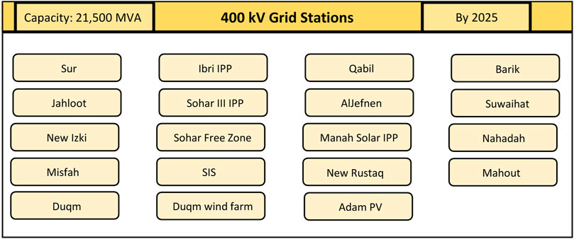
FIGURE 1. Percentage of the allowable limits for different transmission voltage levels.
Furthermore, the 220 kV double-circuit lines connected around the north of Oman play an important role in the Oman transmission system by supporting the 132 kV system and relieve the load of 132 kV. For example, a supporting 220 kV double line has been commissioned in 2010 to link the Sohar Interconnection Station (SIS) and Mahadha and provide a support to the connection link between the OETC system and the Gulf Cooperation Council Interconnection Authority (GCCIA) grid through the United Arab Emirates (Bayram and Mohsenian-Rad, 2016).
In addition, the compliance of the voltage level limits defined by the grid codes is one of the technical requirements considered in the transmission system in OETC. Table 1 shows the voltage levels with the tolerance allowable limits according to the grid codes of Oman (Oman Electricity and Tran, 2020a).

TABLE 1. Percentage of the allowable limits for different transmission voltage levels.
Design Standards
In the designing and planning stages of 400, 220, and 132 kV transmission systems, OETC follows Oman electrical standards along with the grid code requirements. Oman Electrical Standard (OES) 11 specifies the general specifications for electrical materials and equipment, 132 kV design parameters including maximum voltage and fault level, and if the system requires to be solidly grounded and also describes the worst condition to be followed in the design and planning purpose as follows (Oman Electricity and Tran, 2011):
i. Maximum ambient temperature = 50°C
ii. Maximum surface temperature for metal surfaces = 80°C
iii. Altitude (between the sea level and 300 m above the sea level)
iv. Maximum wind velocity = 125 km per hour
v. Average annual rainfall = 117 mm
vi. Maximum relative humidity = 100%
There are several OESs which are followed by the OETC, which can be listed as follows:
➢Oman Electrical Standard OES 25A and 25B
➢Oman Electrical Standard OES 27
➢Oman Electrical Standard OES 32
➢Standard specification for 132/33 kV Substations
➢Standard specification for 220/132/33 kV Substations
➢Standard specification for 400/220/33 kV Substations
➢Standard specification for 400/132/33 kV Substations
➢Standard specification for 132 kV Overhead Lines
➢Standard specification for 220 kV Overhead Lines
➢Standard specification for 400 kV Overhead Lines
➢Standard specification for Underground Cable Circuits above 33 kV up to 150 kV
➢Standard specification for Underground Cable Circuits above 150 kV up to 400 kV
However, the OETC is following its own standards in some cases, where OESs are not applicable for the purpose of planning and designing of 400, 220, and 132 kV transmission systems. For example, the OETC adopted the following standards for the parameters of outdoor transmission equipment that describes the worst-case conditions:
➢Average minimum ambient temperature = 12°C
➢Design minimum ambient temperature = 5°C
➢Average maximum ambient temperature = 38°C
➢Design maximum ambient temperature = 50°C
➢Maximum temperature of the metal surface in direct sunlight = 80°C
➢Mean relative humidity (max/avg.) = 86%/72%
➢Maximum relative humidity = 100%
➢Minimum relative humidity = 15%
➢Average annual rainfall = 145 mm
➢Highest annual rainfall = 638 mm
Protection and Fault Requirements
The OETC follows several transmission system protection requirements in order to guarantee high-level transmission performance and to play an effective channel between the generation plants and the distribution clients. The stipulated grid codes in Oman and Electrical Connection Agreement (ECA) for the OETC, and other generation and distribution companies are the required platforms to approve the transmission protection schemes. These are described in the following subsection
Protection and Relay Settings
It is approved that the setting of the protection relay should be coordinated across the point of connection following the ECA in order to provide an efficient disconnection system of the faulty plant. According to the Data Transfer Code (DTC), the relay protection settings and operation values should not be modified, except when both OETC and the user agree taking into account that the OETC or the user shall not unreasonably withhold their consent. In addition, the main protection faults clearance time of the user equipment which is directly connected to the OETC transmission network and the OETC transmission system main fault clearance time from the starting point of the fault to the circuit breaker arc extinction should not be more than 100 ms. In case of any slower clearance times for faults on the transmission system, there is a need to write an agreement between OETC and the user or the client, which should be specified.
The main important factor in the agreement of a slower fault clearance time is to comply with ECA. The time setting of the faster faults is allowed for the user equipment provided that discrimination is achieved in order to indicate the location of the faults in either OETC equipment or the user’s equipment. The protection coordination of the distribution companies or the generation plants must follow the auto-reclose policy provided by OETC.
Backup Protection
The distribution companies and the generation plant companies connected to the transmission system should tool up with a backup protection at the connection point to cover any failure in the main protection system. In addition, OETC should also tool up with a backup protection which is coordinated with the client backup protection for the discrimination purpose, and all these backup protections should prevent any damage in the equipment. The discrimination between OETC and other users is done by making the fault clearance time of OETC protection slower than the fault clearance time of other users. The licensed distribution users and the direct connected users should provide a backup protection with fault clearance time not slower than the following:
•500 ms for the protection systems including 100 main protection and 400 backup protection in the voltage levels of 400, 220, and 132 kV.
•800 ms for the protection systems including 100 main protection and 700 backup protection in the voltage level of 33 kV.
Protection of User Plant and Equipment
The users of the transmission systems, either generation plant users or distribution network users, are allowed to get the consultation from the OETC regarding protection systems technical requirements. However, the OETC provided a clear recommendation to the users to enhance their system with the precautions against any kind of disturbance that may occur in the transmission system including the following:
• Load unbalance.
• Overvoltage.
• Undervoltage.
• Overfrequency.
• Underfrequency.
• Any combination of over-/under (O/U)-voltage or O/U frequency that may lead to overfluxing.
• Single- and three-phase auto-reclosing.
In addition, OETC specify that in case of frequency divergences outside the limits of 51.5 Hz to 47.5 Hz, the power producers are responsible for their equipment protection against any damage that may occur and they are allowed to disconnect their plants from the system. Furthermore, power producers must protect the generation equipment from any kind of interaction between as follows:
➢The supply voltage waveform, frequency, and harmonics that may occur
➢Any frequency mechanical resonance of the generation units.
Failure of the Circuit Breaker
➢The circuit breakers in the transmission system of voltage levels of 400, 220, or 132 kV should be provided by either OETC or the client according to the agreement between them. However, the circuit breaker must be equipped with a failure protection in order to initiate a tripping signal to the adjacent circuit breakers to be able to eliminate the faulty current within a total time of 300 ms from the beginning of the fault.
Supply Security and Power Flow
The Sultanate of Oman is witnessing a steady increase in population, where the last published estimated number of the population is 5,175,047 (Author Anonymous, 2019), as earlier stated. As a result, the electricity peak demand will keep increasing, as shown in Figure 2 (Hasan et al., 2019). Therefore, the electricity sector in Oman should keep up with developments and updates to ensure steady power supply security without any interruption.
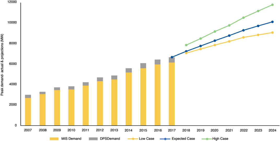
FIGURE 2. Historical and projected electricity peak demand in Oman.
The stability protection framework is used to prevent the inadmissible events which may happen to the power system, such as system interruptions and blackouts. Some examples of single power blackouts which happened previously in the year of 2013 are as follows (Abdalla et al., 2012b):
-Blackout of Barka IPP,
-Blackout of Sur PP, and
-Blackout of Sohar PP.
Supply Security
OETC is responsible for delivering electricity to customers without any interruption. However, if there is any electric equipment out of service, such as cables, circuit breakers, and lines, the operating voltage of the transmission system may reduce to any level specified for such purposes in the grid code. It is necessary that the transmission system should follow the Transmission Security Standard (TSS) requirements based on Table 2. It explains the boundaries of each demand class and the security level requirements during the outage for restricted and maintenance periods.
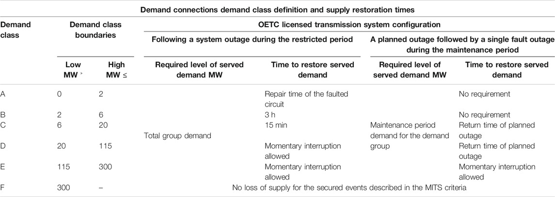
TABLE 2. Demand connections–demand class specification.
Power Flow and Voltage Profiles of MITS and the Dhofar Transmission System
The OETC transmission system load is affected by seasons in Oman. The load in the summer season is the extreme case, while the load in the winter season is less. By recognizing both cases, low and high loads, it is easy to identify the transmission system and highlight its weakness and strength. From the peak demand information, we can notify if there is an overloading risk or not. Also, it shows if the system voltages fall below the voltage limits, which is defined in the grid code.
In order to ensure that OETC will cover the demand, it conducted load flow studies of maximum load demand versus the generation capacity of the existing plants in MITS and the Dhofar Transmission System (DTS) for the period of 5 years (2021–2025), as shown in Table 3. For the peak demand case, the reactive power backup and voltage support will be turned on. An example of this is at 33 kV grid stations, where the capacitor banks will be turned on. In addition, both generator–transformer taps and generator terminal voltage are commonly set at their nominal values.
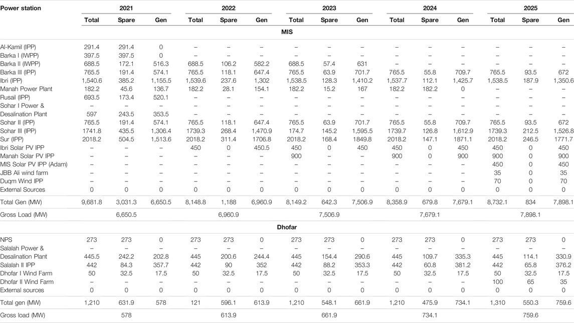
TABLE 3. Summary of connected generation used in load flow studies of maximum demand.
Moreover, the minimum demand case places a risk at the busbar voltages if it is above the voltage limits which are mentioned in the grid codes. The shunt reactors are used in 400 kV lines at MIS under light load conditions (winter) for the purpose of absorbing the extra amount of the reactive power. In summer, 2023–2025, the shunt reactors in the north–south 400 kV interconnector will be installed. OETC reduced the generation at the low load demand to a level that provides the necessary margin of reserve capacity that is consistent with the operational practices. In Table 4, the names of power plants which will be in service during the minimum load demand (for both MITS and DTS) are given.
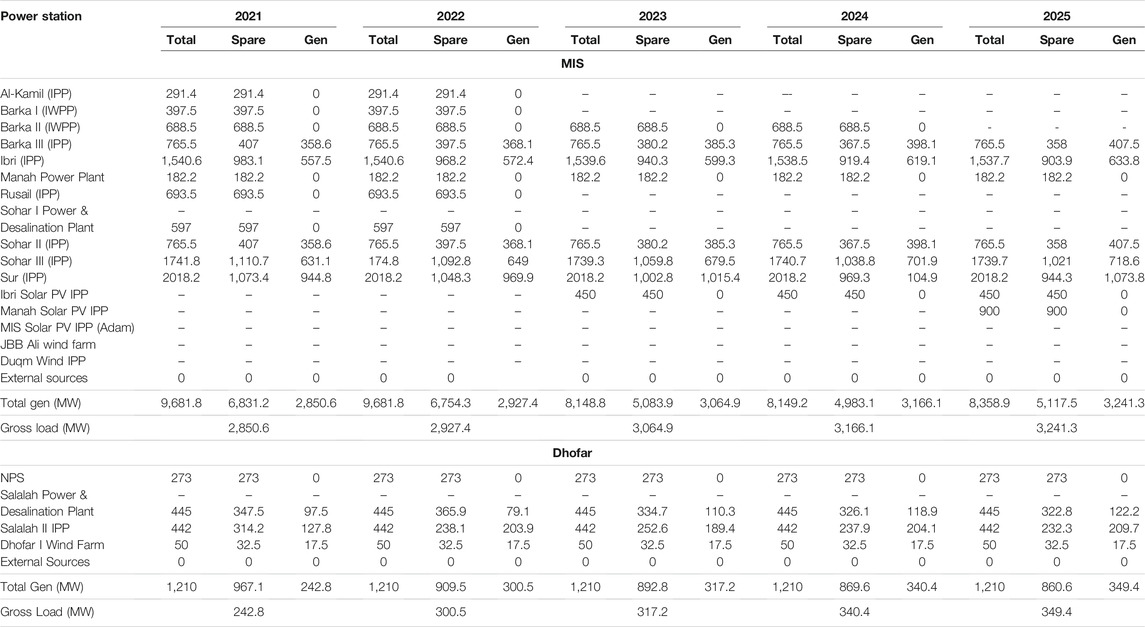
TABLE 4. Summary of connected generation used in load flow studies of minimum demand.
Voltage Profile of MITS
Some points that describe the voltage profile rules at MITS are as follows:
-As per the grid code requirements, the voltage at 400 kV busbars should maintain within the ±5% voltage limit in both cases of high and low demands.
-As per the grid code requirements, the voltage at 220 kV and 132 kV busbars should maintain within the ±10% voltage limit in both cases of minimum and maximum demands.
-The voltage at 33 kV busbars should maintain within the ±6% voltage limit in both cases of high and low demands as per the grid code requirements.
Figure 3 shows the peak and off-peak voltage profiles at different power grids such as 400, 220, 132, and 33 kV in the year 2021, while Figure 4 shows the peak and off-peak voltage profiles at 400, 220, 132, and 33 kV grid stations in 2025. In the peak case, the maximum voltage at some 400 kV busbars reached 1.04 pu, and that is close to the voltage limit of 5% because the busbar is close to the generation unit. On the other hand, the off-peak state shows that the voltage reached 1.00 pu, and this is because the load is consumed at a low reactive power. In order to control the voltage and operate it within the limits, shunt reactors will be installed here. Depending on the load, the voltage at 220kV and 132kV busbars can change within the allowable range and the voltage at the grid supply points is maintained at almost a 33 kV level (equal to 1.0 pu).
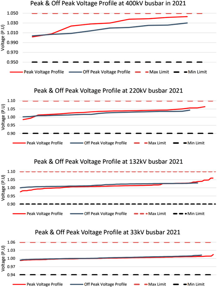
FIGURE 3. MIS peak and off-peak voltage profiles at different power grids in 2021.
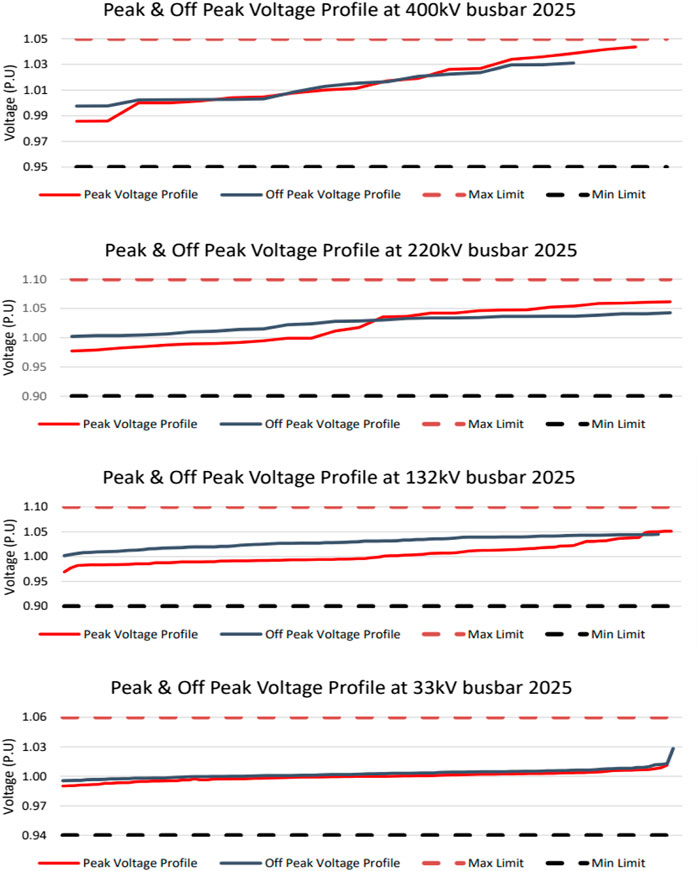
FIGURE 4. MIS peak and off-peak voltage profiles at different power grids in 2025.
Voltage Profile of DTS
Some points that describe the voltage profile rules at DTS are as follows:
• As per the grid code requirements, the voltage at 132 kV busbars should be maintained within the ±10% voltage limit in both cases of maximum and minimum demands.
• The voltage at 33 kV busbars should be maintained within the ±6% voltage limit in both cases of high and low demands, as per the grid code requirements.
Figure 5 shows the peak and off-peak voltage profiles at different power grids of 132 and 33 kV in the year 2021, while Figure 6 shows the peak and off-peak voltage profiles at 132 and 33 kV grid stations in 2025.
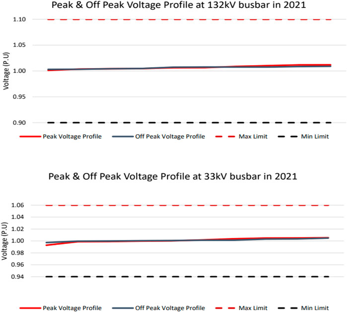
FIGURE 5. DTS peak and off-peak voltage profiles at different power grids in 2021.
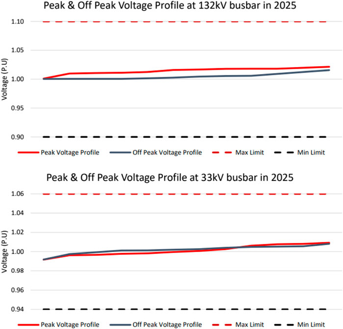
FIGURE 6. DTS peak and off-peak voltage profiles at different power grids in 2025.
Depending on the load, the voltage at the 132 kV busbar can change within the allowable range and the voltage at the grid supply points is maintained almost at the 33 kV level.
System Design and Operational Values
In order to determine the system parameters under various conditions, the grid codes are followed with respect to voltage and frequency. Figure 7 summarizes four conditions that are used to determine the system parameters based on the following conditions:
•Normal conditions: They are the preferred conditions of the OETC licensed transmission system.
•Disturbed conditions: The voltage values here are equal to nominal standards, while the frequency limits are changed.
•Stretched conditions: Here, they have two parts:
-Continuous stretched conditions: not dependent on time.
-Time-limited stretched conditions: cannot last for more than 60 s.
•Unacceptable conditions: They refer to the conditions which are not allowed in operation planning and design (EPRI, 2005; Ota et al., 1996).
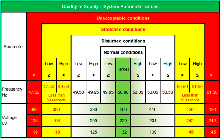
FIGURE 7. Operational values for system design.
Load Dispatch Center
One of the OETC responsibilities is to achieve a balance between load and demand, as shown in Figure 8. This can be done through a Load Dispatch Center (LDC), which controls the generation output for both power systems, MIS and Dhofar Power System (DPS). On a daily basis, it distributes the generation based on availability. In some circumstances, LDC sends dispatch instructions to the generators because the system frequency is out of the standard limits.
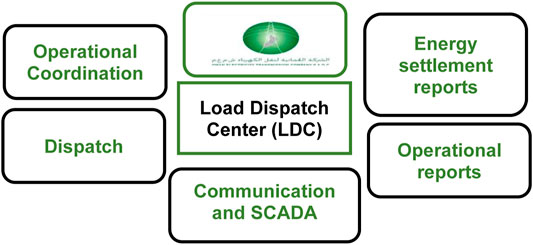
FIGURE 8. Tasks of the load dispatch center in the Oman power grid.
Various Protection Equipment in the Current Power Grid of Oman
The total grid stations in the Oman national power grid, including the main interconnected system and Dhofar system, are 94 grid stations, with a high power system availability of 98.972%. The lengths of 400 kV, 220, and 132 kV transmission lines are 1,382.75, 1959.89, and 4,369.3 km, respectively. Several types of protection relays are used in the protection system of the OETC transmission system, which are listed in Table 5 (Oman Electricity and Tran, 2020b).
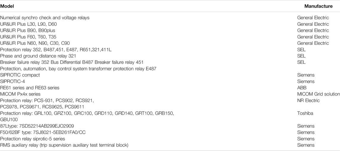
TABLE 5. Protection relay type and manufacturers.
Improvement of the Protection Schemes in the Oman Power Network for Smart Grid Operations
Implementation of the New Technology
The purpose of protection schemes is to protect individual elements in the power system from getting damaged. Also, protection schemes are used for power system security. One of the development technologies in power system protection is avoiding system blackouts using the wide area monitoring (WAM) topology (Okedu et al., 2019; Okedu and WaleedALSalmani, 2019; Al-Badi et al., 2020; Abdallah Al-Balushi et al., 2021). It provides a real-time view for the dynamic behavior of a power system. Through different locations of the power system, WAM collects measurements, combines it, and then transfers it to a single snapshot in a given time. Moreover, this type of technology is more useful in the protection scheme, which needs lower requirement of speed. It is used in adaptive system protection, novel system integrity protection, or a new protection concept. A communication infrastructure is needed for the wide area systems. This communication must ensure that the measurements which are sent from WAM to the protection functions are reliable and fast. As a result, the protection function will be sufficient. The following are the benefits of using WAM in protection systems:
• Managing and addressing the disturbances of the wide area.
• Avoiding inappropriate relay settings for the prevailing system conditions.
• Reducing the hidden failure impacts.
• Ensuring that there is an appropriate balance between the security and dependability of protection. In OETC protection applications, the following important groups of technologies are considered:
• Using phasor measurement units (PMUs), WAM, and global positioning system satellite signals for synchronized measurements of phasors in real time.
• Line differential protection technology.
Development of New Projects
The power system in Oman consists of four separated networks, which are as follows:
-The northern side: MIS.
-The southern side: DPS.
-AD DUQM power system.
-Musandam power system.
At the moment, the northern system MIS and southern system DPS are connected through 132 kV (PDO system). In order to enhance the existing power system in different sides, a new agreement was made between OETC and Oman Power and Water Procurement Company (OPWP) for future 400 kV interconnection between MIS-PDO-DPS and the AD DUQM power system.
The 400 kV north–south interconnection project has different positive effects on both economic and the technical aspects. It will enhance the dispatch coordination which will lead to fuel saving. Moreover, there will be increment in integrating renewable energy systems. Also, by sharing spinning reserves, the operating cost will be reduced. And, the most important benefit is the improvement of power system security and energy management for smart grid operations.
Technical Criteria
Voltage Scenario
As shown in Table 1, the voltage range at 220 and 132 kV busbars in the pre-contingency should maintain within a ±5% voltage limit, while it should maintain a ±10% voltage limit in the post-contingency state. On the other hand, the voltage range at the 400 kV busbar in the pre-contingency state should maintain within a ±2.5% voltage limit. In addition, it should maintain a ±5% voltage limit in the post-contingency state.
Fault Clearing Time Scenario
Table 6 shows the minimum fault clearing time for the equipment or any faulted line in different voltage levels. From Table 6, the fault clearing time should be less than 100 ms in 400 kV, while in 132 and 220 kV, it should be less than 120 ms (Riyami, 2021).
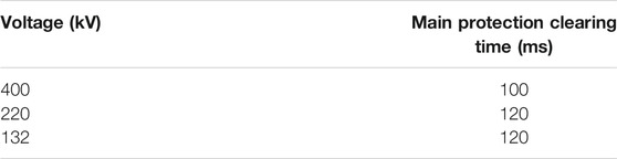
TABLE 6. Fault clearing times.
Voltage Stability Scenario
In order to protect the equipment and load, there is a limit for the fault time and the voltage after faults. After 0.5 s of clearing the fault, the voltage should be more than 0.7 pu, and after 10 s, the voltage should not exceed 0.8–0.9 pu.
Short-Circuit Rating Scenario
Based on the equipment fault level and standard, the maximum single-phase and three-phase short-circuit rating can be determined. Some typical protection schemes in the Oman power grid are shown in Figure 9 for the Shinas, Liwa and Sohar transmission protection schemes and Figure 10 for the Bahla and Sumail transmission protection schemes.
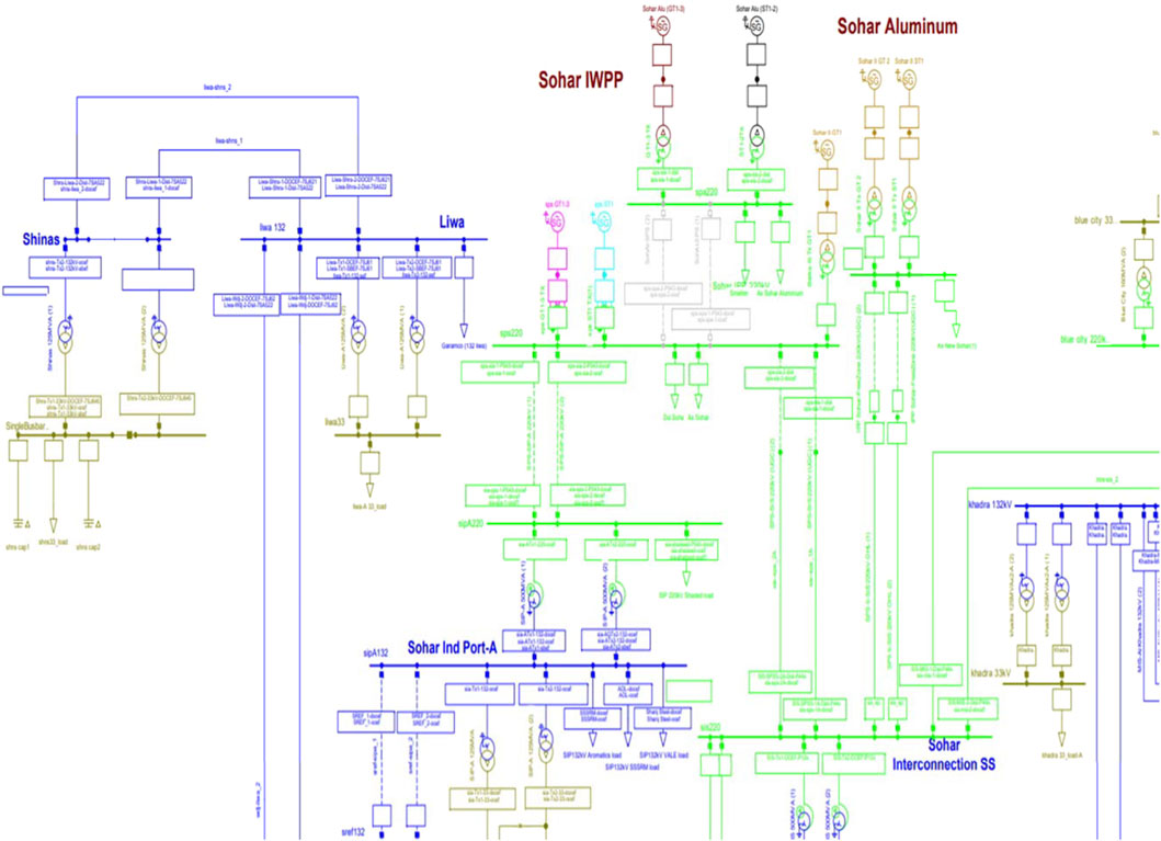
FIGURE 9. Shinas, Liwa and Sohar transmission protection schemes.
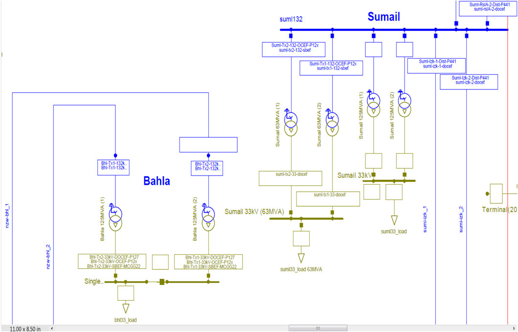
FIGURE 10. Bahla and Sumail transmission protection schemes.
Conclusion
The technical design of the protection schemes of the Oman electricity transmission system has been discussed considering the technical requirements and the nature of the transmission system. The OETC follows different standards that frame the protection scheme of the transmission network such as Oman grid codes and OESs. However, there are several situations where these standards are not applicable for the planning and designing of 400 and 220 kV circuits. Hence, The OETC developed its own standards and policies along with the existing standards in order to overcome any challenges in the future investments on the transmission system, especially in the 400 kV system, for effective energy management. The continuous investment in the transmission system of Oman power grids and the use of updated protection technologies led to the enhancement of the performance of the Oman transmission system and a high power transmission availability of 98.972%.
The specified voltage levels, the grid codes, the system standards, and the balance between demand and the generating power are all part of stability protection frameworks, which were considered in this study. It is used to prevent the inadmissible events which may happen in the power system, like power interruption and blackouts. Consequently, there is a need for new technologies that are used in the power grid of Oman in order to enhance the protection schemes. Moreover, there is a new development project for improving the power security by interconnecting the southern and northern parts of the country. The technical analysis and the improvements obtained from this interconnection would lead to economic and technical benefits. It will connect MIS-PDO-Dhofar with the Duqm area by using a 400 kV interconnection. Other technical benefits may include voltage stability, a short circuit, and the fault clearing time. The diversity of the geographical nature of Oman is an essential challenge in the operation of the Omani national grid. Consequently, the electricity network of Oman includes four separated systems: MIS, DPS, the Musandam power system, and the AD DUQM power system. This separated power structure may be one of the challenges that will be encountered in the implementation of smart grids due to the penetration of renewable energy systems.
Data Availability Statement
The original contributions presented in the study are included in the article/Supplementary Material; further inquiries can be directed to the corresponding author.
Author Contributions
KO did the conceptualization, analysis, writing, and supervision of the paper. SA did the literature review and data collection for the paper. MA did the literature review and data collection of the paper.
Conflict of Interest
The authors declare that the research was conducted in the absence of any commercial or financial relationships that could be construed as a potential conflict of interest.
Publisher’s Note
All claims expressed in this article are solely those of the authors and do not necessarily represent those of their affiliated organizations, or those of the publisher, the editors, and the reviewers. Any product that may be evaluated in this article, or claim that may be made by its manufacturer, is not guaranteed or endorsed by the publisher.
References
Abdalla, O. H., Al-Hadi, H., and Al-Riyami, H. (2009). “Development of a Digital Model for Oman Electrical Transmission Main Grid,” in Proceedings of the 2009 International Conference on Advanced Computations and Tools in Engineering Applications (Lebanon: NDU), 451–456.
Abdalla, O. H., Al-Khusaibi, T., Al-Bitashi, A., Kumar, A., Svalova, I., Watson, P., and Svalovs, A. (2012). “Development of Stability protection Framework in oman Electricity Transmission System,” in Proceedings of the 11th IET International Conference on Developments in Power Systems Protection (Birmingham, UK: DPSP), 23–26. doi:10.1049/cp.2012.0020
Abdalla, O. H., Al-Khusaibi, T., Al-Bitashi, A., Kumar, A., Svalova, I., Watson, P., et al. (2012). Development of Stability protection Framework in Oman Electricity Transmission System. Birmingham, UK: IET Conference Publications, 23–26. doi:10.1049/cp.2012.0020
Abdallah Al-Balushi, M., Ali Alomairi, S., and Okedu, K. E. (2021). Power Situation in Oman and Prospects of Integrating Smart Grid Technologies. Int. J. Smart Grid 5 (1), 45–62.
Al-Badi, A. H., Ahshan, R., Hosseinzadeh, N., Ghorbani, R., and Hossain, E. (2020). Survey of Smart Grid Concepts and Technological Demonstrations Worldwide Emphasizing on the Oman Perspective. Appl. Syst. Innovation 3 (1), 1–27. doi:10.3390/asi3010005
Oman Electricity Transmission Company (OETC) (2011). Swing Study – Final Report”, Project 63795A. Parsons Brinckerhoff: World Bank Population, 1–180.
Authority for Electricity Regulation in Oman (2016). License Condition (26). Second edition. Muscat, Oman: Transmission security standard.
Bayram, İ. Ş., and Mohsenian-Rad, H. (2016). An Overview of Smart Grids in the GCC Region, 166. Berlin-Heidelberg, Germany: Lecture Notes of the Institute for Computer Sciences, Social-Informatics and Telecommunications EngineeringLNICST, 301–313. doi:10.1007/978-3-319-33681-7_25
EPRI (2005). Mitigating Cascading Outages on Power Systems: Recent Research Approaches and Emerging Method. USA: EPRI Report.
Hasan, S., Al Aqeel, T., Al-Badi, A., Bhatt, Y., and Al-Badi, M. (2019). Oman Electricity Sector: Features. Riyadh, Saudi Arabia: Challenges and Opportunities for Market Integration, 1–32. doi:10.30573/KS--2019-DP61
Okedu, K. E., Husam, A. L., and Ahmed, Aziz. (2019). Prospects of Solar Energy in Oman: Case of Oil and Gas Industries. Int. J. Smart Grid, 3, 138–151.
Okedu, K. E., and WaleedAL Salmani, Z. (2019). Smart Grid Technologies in Gulf Cooperation Council Countries: Challenges and Opportunities. Int. J. Smart Grid 3 (2), 92–102.
Oman Electricity and Transmission Company S.A.O.G Product Approved List. Muscat, Oman: OETC PAC-PAL-.
Oman Electricity and Transmission Company “The Annual Five-Year Transmission System Capability Statement (2011-2015)”, 1–136.
Oman Electricity Transmission Company. Annual Report, April 2020, Five-Year Annual Transmission Capability Statement (2020 - 2024). Muscat, Oman: Muscat Office, OETC.
Ota, H., Kitayama, Y., Ito, H., Fukushima, N., Omata, K., Morita, K., et al. (1996). Development of Transient Stability Control System (TSC System) Based on On-Line Stability Calculation. IEEE Trans. Power Syst. 11. doi:10.1109/59.535687
Riyami, H. A. (2021). Technical Evaluation of 400 kV Interconnector between North and South Grid of Oman Technical Evaluation of 400 kV Interconnector between North and South Grid of Oman Summar.
Saudi Electricity Company (2020). [Online]. Available at: https://www.se.com.sa/en-us/Pages/SaudiPowerTransmissionNetwork.aspx. (Accessed 5th May 2021).
Shu, Y., and Chen, W. (2018). Research and Application of UHV Power Transmission in China. High Voltage 3 (1), 1–13. doi:10.1049/hve.2018.0003
Trading Economics (2021). [Online]. Available at: https://tradingeconomics.com/saudi-arabia/land-area-sq-km-wb-data.html, (Accessed May 2nd, 2021).
Worldometer (2021). [Online]. Available at: https://www.worldometers.info/world-population/saudi-arabia-population/ (Accessed May 2nd, 2021).
Keywords: electricity network, Oman power grid, smart grid technologies, voltage profile, transmission system
Citation: Al Omairi S, Al Balushi M and Okedu KE (2021) Overview of Oman Power Transmission System and Protection Schemes for Effective Energy Management in Smart Grid Operations. Front. Energy Res. 9:724501. doi: 10.3389/fenrg.2021.724501
Received: 13 June 2021; Accepted: 01 September 2021;
Published: 13 October 2021.
Edited by:
Jianwu Zeng, Minnesota State University, Mankato, United StatesReviewed by:
Dongliang Xiao, South China University of Technology, ChinaYayu Peng, University of Nebraska at Kearney, United States
Copyright © 2021 Al Omairi, Al Balushi and Okedu. This is an open-access article distributed under the terms of the Creative Commons Attribution License (CC BY). The use, distribution or reproduction in other forums is permitted, provided the original author(s) and the copyright owner(s) are credited and that the original publication in this journal is cited, in accordance with accepted academic practice. No use, distribution or reproduction is permitted which does not comply with these terms.
*Correspondence: Kenneth E. Okedu, a2Vub2tlZHVAeWFob28uY29t, b2tlZHVrZW5uZXRoQG51LmVkdS5vbQ==