 Wei Jiang1*
 Zhiqi Xu
 Saifur Rahman
95% of researchers rate our articles as excellent or good
Learn more about the work of our research integrity team to safeguard the quality of each article we publish.
Find out more
ORIGINAL RESEARCH article
Front. Energy Res. , 28 September 2021
Sec. Smart Grids
Volume 9 - 2021 | https://doi.org/10.3389/fenrg.2021.722606
This article is part of the Research Topic The Emerging Form of Smart Grid: Smart Integrated Energy Systems and Prosumer Centred Energy Community View all 16 articles
A hybrid energy storage system (HESS) consists of two or more types of energy storage components and the power electronics circuit to connect them. Therefore, the real-time capacity of this system highly depends on the state of the system and cannot be simply evaluated with traditional battery models. To tackle this challenge, an equivalent state of charge (ESOC) which reflects the remaining capacity of a HESS unit in a specific operation mode, is proposed in this paper. Furthermore, the proposed ESOC is applied to the control of the distributed HESS which contains several units with their own local targets. To optimally distribute the overall power target among these units, a sparse communication network-based hierarchical control framework is proposed. This framework considers the distributed control and optimal power distribution in the HESS from two aspects - the power output capability and the ESOC balance. Based on the primary droop control, the total power is allocated according to the maximum output capacity of each unit, and the secondary control is used to adjust the power from the perspective of ESOC balance. Therefore, each energy storage unit can be controlled to meet the local power demand of the microgrid. Simulation results based on MATLAB/Simulink verify the effectiveness of the application of the proposed equivalent SOC.
Energy storage systems are widely deployed in microgrids to reduce the negative influences from the intermittency and stochasticity characteristics of distributed power sources and the load fluctuations (Rufer and Barrade, 2001; Hai Chen et al., 2010; Kim et al., 2015; Ma et al., 2015). From both economic and technical aspects, hybrid energy storage systems (HESSs) have several benefits compared to traditional battery-based energy storage systems. In a battery-supercapacitor HESS unit, the requirements for both the energy density and the power density can be satisfied (Zhou et al., 2011). With the help of supercapacitors, the peak power performance of the energy storage system can be enhanced, and thus, the stress on batteries can be reduced, and their lives are extended (Dougal et al., 2002; Gao et al., 2005).
Since a HESS unit usually consists of two or more types of energy storage components and a power electronic circuit to couple them, accurate evaluation of the remaining energy in the system is challenging. In (Mesbahi et al., 2017), an integrated model for energy storage components coupled with power electronic devices is built for an electrical vehicle simulator. In (Dey et al., 2019), an online state and parameter estimation scheme in a battery-double-layer-capacitor system is proposed. However, since the two above approaches focus on specific applications, they cannot be used as comprehensive techniques to evaluate the remaining energy in hybrid energy storage systems.
Meanwhile, energy storage systems are usually widely invested and installed in power system. In a distributed HESS, the HESS units with relatively low power and energy capacities can be equipped where the distributed power sources are located and can be used to suppress local fluctuations and stabilize the node voltage. Through coordinated control of these distributed units, the units can cooperate to fulfill an overall goal in the microgrid, such as stabilizing the transmission line power and providing emergency frequency control, with proper energy evaluation, power allocation strategies and communication links (Zhao et al., 2011; Le Dinh and Hayashi, 2013; Arif and Aziz, 2017; Yongqiang and Tianjing, 2017).
The classical coordinated control methods can be classified into three categories: centralized control, distributed control and decentralized control. Centralized control methods require a high-speed high-throughput data processing center (Tsikalakis and Hatziargyriou, 2008; Tan et al., 2012) and reliable communication between the center and each unit, which results in higher costs and potential risk of failures (Chen and Wang, 2015). The distributed control methods, do not have these requirements (Chandorkar et al., 1993; Shu et al., 2018). However, directly using droop control in a distributed energy storage system without considering the state of charge (SOC) of the energy storage components may cause over-charging and over-discharging problems. To tackle this issue, in (Mokhtari et al., 2013), a distributed control strategy with limited communications between neighboring energy storage units is proposed. In (Li et al., 2014), the output power adjustment of each unit is based on the ratio determined by its SOC level. In (Li et al., 2017), both consistency control and droop control methods are used for frequency adjustment. However, considering the asymmetric characteristics of the energy storage components in a HESS unit, these approaches cannot be directly applied. Decentralized control also has its disadvantages. The local information collected by local controller is limited, so it is difficult to comprehensively consider the dynamic characteristics of all distributed generation and the whole microgrid system. Meanwhile, it is difficult to realize the frequency and voltage regulation of the distributed generation and as well as the economic dispatch of microgrid (Xin et al., 2011). Due to the absence of microgrid central controller (MGCC) and communication system, the recovery speed of voltage and frequency is relatively slow after interference.
In the isolated operation mode of microgrid, the energy storage device can be used to maintain the stability of system frequency and voltage with the distributed generations (Rodrigues et al., 2018). However, few literatures introduce how to utilize the features of the HESS to support the isolated microgrid with a distributed structure.
In this paper, a sparse communication network based hierarchical control structure with considering the equivalent SOC (ESOC) evaluation is proposed, in which the power demand is distributed according to two criteria: 1) the real-time power output ability of each HESS unit and 2) the control in state of charge of each HESS unit.
The rest of this paper is organized as follows. In Equivalent Circuit and SOC of HESS, the generalized equivalent model of HESS and the method of evaluating the remaining energy in HESS is proposed. The power distribution method which considers the real-time power output ability and state of charge of each HESS units is described in Hierarchical Control Structure For Distributed HESS. Simulation results are presented in Simulation Analysis to verify the effectiveness of the proposed method. Conclusions are drawn in Conclusion.
The power conversion system (PCS) connecting the hybrid energy storage components and the AC/DC bus are variously studied (Ghazanfari et al., 2012; Hai-Feng et al., 2014; Kawakami et al., 2014; Tian et al., 2019). The most classic topology is shown in Figure 1A. The battery and the supercapacitor are individually regulated and inverted with DC/DC and DC/AC converters and eventually paralleled connected to the AC bus. To enhance the output voltage level and improve power quality, the cascaded HESS system has been investigated, as shown in Figure 1B, In this structure, each energy storage component is connected to an H-bridge, and multiple H-bridges are series-connected to form high-voltage output. The output power of the unit can be flexibly controlled by regulating the amplitude and phase of the output voltage.
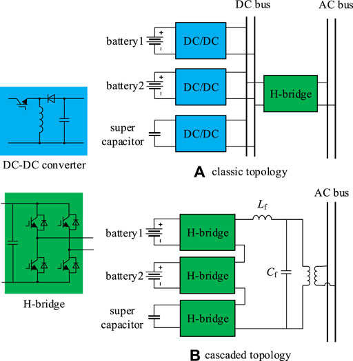
FIGURE 1. Topology of a single-phase HESS unit.
In this paper, the cascaded structure is selected to be the PCS of HESS units since it is more complicated than the traditional parallel-connected converters. It should be noted that the proposed ESOC evaluation algorithm can also be applied to other HESS PCS topologies.
Considering different levels of power demand, cascaded modules in Figure 1B usually operate in asymmetric states. For example, when high power surge emerges, the supercapacitor modules need to enhance power output by increasing their terminal voltages. In this case, the remaining operation duration highly depends on the SOC of the supercapacitor. In contrast, when the output power is relatively low, the operation duration is mainly related to the SOC of the battery since the supercapacitor modules are standby.
Therefore, the equivalent SOC of the HESS units hinges on its operation mode and the dominating energy storage component. There are totally four different modes:
1) Standby mode: The HESS unit does not inject or absorb active power.
2) Operation mode 1 (normal power): The active power injection or absorption requirement is within the ability of the batteries, so only batteries are injecting or absorbing power. The supercapacitors are used as an energy buffer.
3) Operation mode 2 (instantaneous peak power): When peak power requirement which lasts shorter than the dynamic response time constant of the batteries occurs, batteries are on standby, and only supercapacitors are injecting or absorbing power.
4) Operation mode 3 (continuous high power): To meet the continuous high power requirement, all the batteries and supercapacitors are injecting or absorbing power simultaneously.
The equivalent circuit model of the HESS unit is the basis of the accurate evaluation of the SOCs of each component in and the equivalent SOC of a HESS unit. A HESS unit consists of batteries, supercapacitors and H-bridges.
The equivalent circuits of the battery and the supercapacitor are introduced in (Newman et al., 2003) and (Li et al., 2016) respectively. In addition to these components, the equivalent circuit of the H-bridge is proposed in this paper. The complete model, which is composed of the equivalent circuits of these three components, is further simplified as a generalized equivalent circuit for ESOC definition purposes.
The equivalent circuit of the H-bridge is shown in Figure 2. K is chosen from −1, 0 and 1, determined by the control signal of the PWM.
where T is the sampling period;
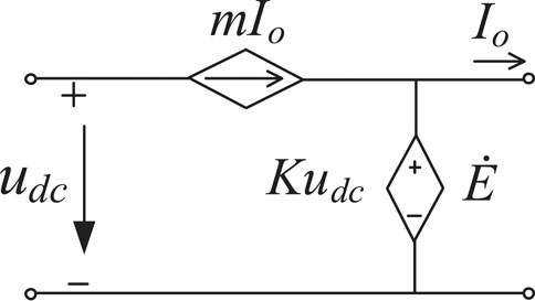
FIGURE 2. Equivalent circuit of H-bridge.
According to the equivalent circuits of the battery, the supercapacitor and the H-bridge, the equivalent circuit of a HESS unit is shown in Figure 3.

FIGURE 3. Equivalent circuit of a HESS unit.
In Figure 3, the output voltage
where
The output voltage
where the parameters
The complete model shown in Figure 3 is too complex for analysis and thus needs further simplification. Based on the principle of combining the adjacent energy storage components of the same type without changing the output power, the model can be simplified as the generalized equivalent circuit, which is shown in Figure 4.
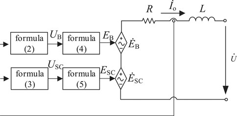
FIGURE 4. Equivalent circuit of a HESS unit.
In Figure 4, two controlled voltage sources (CVSs) are used to represent two types of energy storage components (the battery and the supercapacitor). The resistor
where
Based on the generalized equivalent circuit (Figure 4), the SOC of each energy storage component is defined as
where ∗ represents the type of energy storage component (
Based on the SOCs of the energy storage components in a HESS unit, this paper proposes equivalent SOC (ESOC) to reflect the state of charge of a HESS unit by a comprehensive consideration of the operating conditions of all the energy storage components in the HESS unit. It is defined as
where
where k and l are small constants, which are used to judge the working states of the battery and the supercapacitor, respectively.
Considering the difference of the ESOC ranges of each energy storage unit under different modes, if we simply control the ESOC of all units to tend to a global average
where
The changes of
Figure 5 shows the hierarchical control framework of the distribute HESS proposed in this paper. The distributed control strategy is mainly divided into two levels: the primary control and the secondary control. The lower level is the local droop control. According to the maximum output power of the energy storage unit in different modes, the output power of each energy storage unit can be reasonably allocated by using the droop coefficient of different modes, and the power can be allocated once without the aid of communication. The upper level secondary control is a consistency control. In order to reduce the difference of
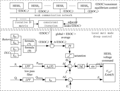
FIGURE 5. The hierarchical control framework of distributed HESSs.
The main control targets of this hierarchical framework include:
1) In order to respond to the power fluctuation of the system, it is necessary to determine the operation mode of each HESS unit according to the total power demand assessment results, so as to determine the P-F droop control coefficient. In this way, active power can be optimally distributed among all HESS units.
2) In order to share the control target among units, the distributed algorithm based on discrete consistency principle is used. The average value of each energy storage unit
3) On the basis of variable droop coefficient control, the correction considering
Traditional droop control is difficult to comprehensively consider the above objectives.
Considering that the power distribution control of the distributed energy storage system is discontinuous, the first-order discrete-time consistency algorithm is utilized (Yinliang et al., 2011). For the distributed multi-agent control system with n agents, the discrete-time consistency algorithm can be expressed as:
where:
Eq. 11 can also be written as a matrix:
where,
If all elements of matrix D are nonzero, and the sum of elements in each row and column is 1, then D is called a bi-random matrix (Alfred, 1954). According to Gerschgorin’s disks theorem, all eigenvalues of matrix D are less than or equal to 1. In order to apply Perron Frobenius lemma:
where
According to the above lemma, a positive definite Lyapunov function is constructed to analyze the stability of the system. Finally, the following conclusion is obtained: if Aij in D matrix satisfies the following equation, the designed system is stable:
where ni and nj are the number of adjacent nodes of node i and j respectively.
Therefore, in this paper, the D-matrix satisfying Eq. 16 is constructed by means metropolis method (Xu and Liu, 2011), which has high convergence speed.
where Ni is the set of nodes connected with node i, and ε is a very small number. When the number of system nodes is large and complex, it can be set to 0.
Under the condition of inductive equivalent line impedance, the droop control equation of parallel Hess is as follows:
where
If the active droop coefficient is set according to the ratio of the maximum output power of each energy storage unit, the load power can be distributed in proportion among the energy storage units.
In addition, in order to avoid large frequency offset, the active power droop coefficient
where
Similarly, the reactive power distribution in distributed energy storage system is related to the reactive power droop coefficient
where
Because the maximum output active power of Hess varies with different working modes, the traditional droop control method with fixed droop coefficient is not suitable for Hess application. Therefore, this paper considers the way of changing the droop coefficient in different modes, so that the local droop control of energy storage system can be adjusted according to the maximum output active power at any time and in any mode. The calculation formula of active power droop coefficient considering sub mode is as follows:
where
In order to achieve the balance of each energy storage unit
where:
To verify the proposed ESOC evaluation method, a simplified model consists of a cascaded HESS unit connected to a load is built in the Matlab/Simulink platform. The HESS unit switches between different modes and the ESOC is calculated in real-time. The rated capacity and initial SOC condition of the battery and supercapacitor in this HESS unit is shown in Table 1.

TABLE 1. Parameters of the energy storage components.
The simulation was taken in four stages (0–3, 3–5, 5–10, 10–20 min), corresponding to operation mode 1, 2, 1 and 3 respectively. The details of the three operation modes are introduced in Section II (a). Figure 6 shows the changes in ESOC and its normalized value < ESOC> during the four stages.
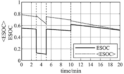
FIGURE 6. ESOC and normalized ESOC.
The HESS unit was operating in mode 1 from 0 to 3 min and from 5 to 10 min. In these time periods, only the batteries inject power to the load and the supercapacitor is standing by. That means that the remaining energy in the HESS unit totally depends on the remaining energy in the battery. Therefore, the remaining energy in the ESOC is completely determined by the SOC of the battery.
The HESS unit was operating in mode 2 from 3 to 5 min, in the time period when instantaneous extreme high power demand occurs. The provided power from HESS to the load almost all comes from the supercapacitors. Thus, the remaining energy in the HESS unit totally depends on the remaining energy in the supercapacitors. The capacity of the supercapacitors is much smaller than that of the battery, so there is a significant drop in ESOC.
The HESS unit was operating in mode three from 10 to 20 min. To meet the high power demand, both the battery and the supercapacitors provide power to the load, so there is an increase in ESOC when switching from operation mode 1. This increase in ESOC indicates that the remaining energy in the supercapacitors starts to be injected to the load in addition to the remaining energy in the battery.
Figure 6 also illustrates that while the <ESOC > has a linear relationship with the ESOC, the change in the ESOC when switching the operation mode is mitigated in the <ESOC>. This can avoid too acute changes in the power distribution, which may cause HESS units to go beyond their appropriate operation ranges.
The model shown in Figure 7 is used to verify the proposed control framework to support the isolated microgrid. The equivalent output impedance of the power network used in the voltage level 220 V is inductive.
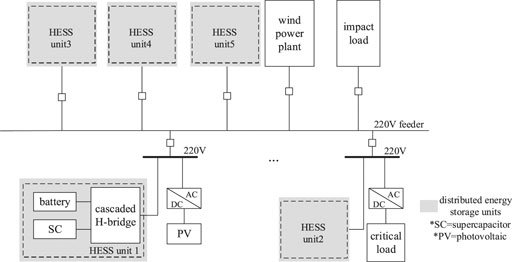
FIGURE 7. Simulation model.
The configurations of the five HESS units are shown in Table 2.
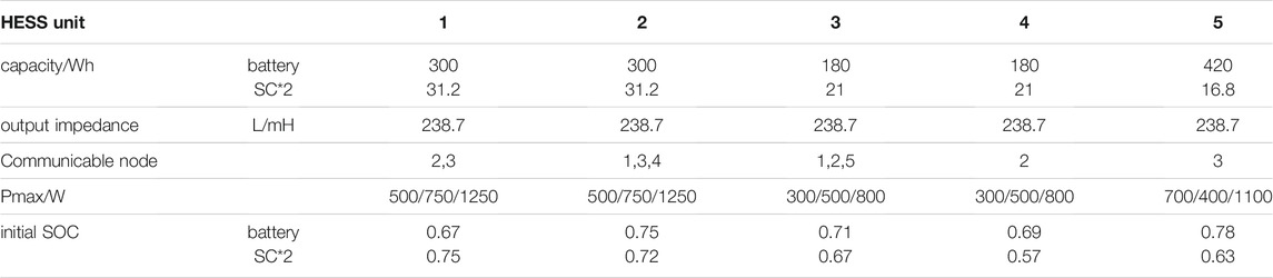
TABLE 2. Parameters and Initial SOCs of each HESS Unit.
As the isolated microgrid, the simulation model contains wind power, photovoltaic and other renewable energy. These distributed generators usually use the algorithm to track the maximum power point for PQ control, and the output active power is intermittent and random. Meanwhile, the load also has the stochastic characteristics. Thus, the HESSs are used to meet the difference between generations and usage, as well as to suppress the power fluctuations.
Figure 8 shows overall generations, loads and their difference of the isolated microgrid. The HESSs unit is used to support the microgrid when severe failure occurs and the distributed generations cannot meet the load demand. In this situation, all HESS units will share the total difference.
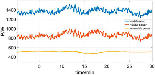
FIGURE 8. The power demand of isolated microgrid.
The proposed hierarchical control framework is used to allocate power among HESS units. Figure 9 shows the output power of these HESS units in the first 30 min. The simulation process is divided into three stages. From 0 to 3 min, the primary control is enabled, and each HESS unit contribute to the active power demand according to its own state. From 3 to 18 min, since the secondary control is activated, the output power of HESS5 with relatively large capacity and HESS2 with high initial SOC increases significantly. In 18–30 min, With the consistency process of the normalized ESOC of the five HESS units, the ESOC is gradually consistent.
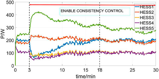
FIGURE 9. Active power injection of each HESS unit in the initial 30 min.
Figure 10 shows the changes in <ESOC> of these HESS units in the first 30 min. In 0–3 min, the
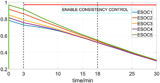
FIGURE 10. Normalized ESOC of the five HESS units.
In this paper, the equivalent SOC (ESOC) is proposed as an index to evaluate the state of charge of a HESS unit considering its operation mode. Based on this, a distributed control method is proposed that aims to optimize the power allocation among HESS units that are in the same microgrid. The main innovations are: consideration of the operation mode of a HESS unit while evaluating its state of charge, and determining the droop coefficient of primary control. Use the distributed algorithm and secondary control to balance the equivalent SOC among HESS units. Simulation results show that the proposed ESOC can reflect the actual condition of a HESS unit according to its operation mode. Meanwhile, with the proposed distributed control method, the power can be reasonably allocated among all HESS units considering their current states and their ESOC targets.
The raw data supporting the conclusions of this article will be made available by the authors, without undue reservation.
WJ: Conceptualization, Methodology, Funding acquisition, Investigation, Supervision, Validation, Visualization, Writing—original draft, Writing—review and editing. ZX: Data curation, Visualization, Writing—review and editing. BY: Validation, Visualization, Writing—review and editing. KS: Validation, Visualization, Writing—review and editing. KR: Validation, Visualization, Writing—review and editing. YD: Validation, Visualization, Writing—review and editing. SR: Validation, Visualization, Writing—review and editing.
This work was supported by the National Natural Science Foundation of China under Grant 51877041.
Author KS was employed by State Grid Zhejiang Electric Power Co., Ltd.
The remaining authors declare that the research was conducted in the absence of any commercial or financial relationships that could be construed as a potential conflict of interest.
All claims expressed in this article are solely those of the authors and do not necessarily represent those of their affiliated organizations, or those of the publisher, the editors and the reviewers. Any product that may be evaluated in this article, or claim that may be made by its manufacturer, is not guaranteed or endorsed by the publisher.
Alfred, Horn. (1954). Doubly Stochastic Matrices and the Diagonal of a Rotation Matrix. Am. J. Math. 76 (3), 620–630.
Arif, S., and Aziz, T. (2017).Study of Frequency Response with Centralized vs. Distributed Placement of Battery Energy Storage Systems in Renewable Integrated Microgrid. 2017 IEEE International WIE Conference on Electrical and Computer Engineering. Dehradun: WIECON-ECE), 96–99. doi:10.1109/wiecon-ece.2017.8468928
Rufer, A., and Barrade, P., "A supercapacitor-based energy storage system for elevators with soft commutated interface," Conference Record of the 2001 IEEE Industry Applications Conference. 36th IAS Annual Meeting (Cat. No.01CH37248), Chicago, IL, USA, 2001, pp. 1413–1418 vol.2.
Chandorkar, M. C., Divan, D. M., and Adapa, R. (1993). Control of parallel connected inverters in standalone AC supply systems. IEEE Trans. Industry Appl. 29 (1), 136–143.
Chen, W., and Wang, G. (2015). Decentralized Voltage-Sharing Control Strategy for Fully Modular Input-Series-Output-Series System with Improved Voltage Regulation. IEEE Trans. Ind. Electron. 62 (5), 2777–2787. doi:10.1109/tie.2014.2365433
Li, Chendan., Dragicevic, T., Diaz, N. L., Vasquez, J. C., and Guerrero, J. M., "Voltage scheduling droop control for State-of-Charge balance of distributed energy storage in DC microgrids," IEEE International Energy Conference (ENERGYCON), Cavtat, 2014, pp. 1310–1314. doi:10.1109/energycon.2014.6850592
Dey, S., Mohon, S., Ayalew, B., Arunachalam, H., and Onori, S. (2019). A Novel Model-Based Estimation Scheme for Battery-Double-Layer Capacitor Hybrid Energy Storage Systems. IEEE Trans. Contr. Syst. Technol. 27 (2), 689–702. doi:10.1109/tcst.2017.2781650
Dougal, R. A., Liu, S., and White, R. E. (2002). Power and life extension of battery-ultracapacitor hybrids. IEEE Trans. Comp. Packag. Technol. 25 (1), 120–131. doi:10.1109/6144.991184
Gao, L., Dougal, R. A., and Liu, S. (2005). Power Enhancement of an Actively Controlled Battery/Ultracapacitor Hybrid. IEEE Trans. Power Electron. 20 (1), 236–243. doi:10.1109/tpel.2004.839784
Ghazanfari, A., Hamzeh, M., Mokhtari, H., and Karimi, H. (2012). Active Power Management of Multihybrid Fuel Cell/Supercapacitor Power Conversion System in a Medium Voltage Microgrid. IEEE Trans. Smart Grid 3 (4), 1903–1910. doi:10.1109/tsg.2012.2194169
Hai Chen, H., Dongsheng Ma, B., and Ma, D. (2010). Energy Storage and Management System with Carbon Nanotube Supercapacitor and Multidirectional Power Delivery Capability for Autonomous Wireless Sensor Nodes. IEEE Trans. Power Electron. 25 (12), 2897–2909. doi:10.1109/tpel.2010.2081380
Hai-Feng, G., Man, C., Yang, C., Qin-Dong, M., and Zhi-Bin, L. (2014).Design of 2MW/10kV cascaded H-bridge power conversion system. 2014 International Conference on Power System Technology. Chengdu, 3335–3340. doi:10.1109/powercon.2014.6993906
Kawakami, N., Iijima, Y., Li, H., and Ota, S. (2014).High efficiency power converters for battery energy storage systems. 2014 International Power Electronics Conference (IPEC-Hiroshima 2014 - ECCE ASIA). Hiroshima, 2095–2099. doi:10.1109/ipec.2014.6869877
Kim, S.-T., Bae, S., Kang, Y. C., and Park, J.-W. (2015). Energy Management Based on the Photovoltaic HPCS with an Energy Storage Device. IEEE Trans. Ind. Electron. 62 (7), 4608–4617. doi:10.1109/tie.2014.2370941
Le Dinh, K., and Hayashi, Y. (2013).Coordinated BESS control for improving voltage stability of a PV-supplied microgrid. 2013 48th International Universities' Power Engineering Conference. Dublin: UPEC), 1–6. doi:10.1109/upec.2013.6715027
Li, C., Coelho, E. A. A., Dragicevic, T., Guerrero, J. M., and Vasquez, J. C. (2017). Multiagent-Based Distributed State of Charge Balancing Control for Distributed Energy Storage Units in AC Microgrids. IEEE Trans. Ind. Applicat. 53 (3), 2369–2381. doi:10.1109/tia.2016.2645888
Li, X., Xu, T., Tan, S., Chen, X., and Zeng, X. (2016). Integrated dynamic equivalent model of super capacitor energy storage system. in J. Syst. Simulation 28 (04), 783–792+799. (in Chinese).
Ma, T., Yang, H., and Lu, L. (2015). Development of hybrid battery-supercapacitor energy storage for remote area renewable energy systems. Appl. Energ. 153, 56–62.
Mesbahi, T., Rizoug, N., Khenfri, F., Bartholomeüs, P., and Le Moigne, P. (2017). Dynamical modelling and emulation of Li-ion batteries–supercapacitors hybrid power supply for electric vehicle applications. IET Electr. Syst. Transportation 7 (2), 161–169.
Mokhtari, G., Nourbakhsh, G., and Ghosh, A. (2013). Smart Coordination of Energy Storage Units (ESUs) for Voltage and Loading Management in Distribution Networks. IEEE Trans. Power Syst. 28 (4), 4812–4820. doi:10.1109/tpwrs.2013.2272092
Newman, J., Thomas, K. E., Hafezi, H., and Wheeler, D. R. (2003). Modeling of lithium-ion batteries. J. Power Sourc. 119-121 (121), 838–843. doi:10.1016/s0378-7753(03)00282-9
Rodrigues, Y. R., Monteiro, M. R., Zambroni de Souza, A. C., Riberiro, P. F., Wang, L., and Eberle, W. (2018). “Adaptative Secondary Control for Energy Storage in Island Microgrids,” in IEEE Power & Energy Society General Meeting (Portland, OR, USA: (PESGM), 1–5. doi:10.1109/PESGM.2018.8586228
Shu, L., Chen, W., and Jiang, X. (2018). Decentralized Control for Fully Modular Input-Series Output-Parallel (ISOP) Inverter System Based on the Active Power Inverse-Droop Method. IEEE Trans. Power Electron. 33 (9), 7521–7530. doi:10.1109/tpel.2017.2773559
Tan, K. T., Peng, X. Y., So, P. L., Chu, Y. C., and Chen, M. Z. Q. (2012). Centralized Control for Parallel Operation of Distributed Generation Inverters in Microgrids. IEEE Trans. Smart Grid 3 (4), 1977–1987. doi:10.1109/tsg.2012.2205952
Tian, K., Ali, S., Huang, Z., and Ling, Z. (2019).Power control and experiment of 2MW/10kV cascaded H-bridge power conversion system for battery energy storage system. 8th Renewable Power Generation Conference. Shanghai, China: RPG 2019, 1–7. doi:10.1049/cp.2019.0378
Tsikalakis, A. G., and Hatziargyriou, N. D. (2008). Centralized Control for Optimizing Microgrids Operation. IEEE Trans. Energ. Convers. 23 (1), 241–248. doi:10.1109/tec.2007.914686
Xin, H., Qu, Z., Seuss, J., and Maknouninejad, A. (2011). A Self-Organizing Strategy for Power low Control of Photovoltaic enerators in a Distribution Network [J]. IEEE Trans. Power Syst. 26 (3), 1462–1473.
Xu, Y., and Liu, W. (2011). Novel Multiagent Based Load Restoration Algorithm for Microgrids. IEEE Trans. Smart Grid 2 (1), 152–161. doi:10.1109/tsg.2010.2099675
Yinliang, Xu., Wenxin, Liu., and Jun, Gong. (2011). Stable Multi-Agent-Based Load Shedding Algorithm for Power Systems[J]. IEEE Trans. Power Syst. 26 (4), 2006–2014.
Yongqiang, Z., and Tianjing, W. (2017). Comparison of centralised and distributed energy storage configuration for AC/DC hybrid microgrid. J. Eng. 2017, 1838–1842. doi:10.1049/joe.2017.0649
Zhao, B., Yu, Q., Wang, L., and Xiao, Y. (2011). Bi-directional extensible converter and its distributed control strategy for battery energy storage grid-connected system. Proc. CSEE 31 (S1), 244–251.
Keywords: consistency algorithm, variable droop coefficient, hybrid energy storage system, state of charge, hierarchical control structure
Citation: Jiang W, Xu Z, Yu B, Sun K, Ren K, Deng Y and Rahman S (2021) Control of the Distributed Hybrid Energy Storage System Considering the Equivalent SOC. Front. Energy Res. 9:722606. doi: 10.3389/fenrg.2021.722606
Received: 09 June 2021; Accepted: 09 August 2021;
Published: 28 September 2021.
Edited by:
Yingjun Wu, Hohai University, ChinaReviewed by:
Kailong Liu, University of Warwick, United KingdomCopyright © 2021 Jiang, Xu, Yu, Sun, Ren, Deng and Rahman. This is an open-access article distributed under the terms of the Creative Commons Attribution License (CC BY). The use, distribution or reproduction in other forums is permitted, provided the original author(s) and the copyright owner(s) are credited and that the original publication in this journal is cited, in accordance with accepted academic practice. No use, distribution or reproduction is permitted which does not comply with these terms.
*Correspondence: Wei Jiang, amlhbmd3ZWlAc2V1LmVkdS5jbg==
Disclaimer: All claims expressed in this article are solely those of the authors and do not necessarily represent those of their affiliated organizations, or those of the publisher, the editors and the reviewers. Any product that may be evaluated in this article or claim that may be made by its manufacturer is not guaranteed or endorsed by the publisher.
Research integrity at Frontiers
Learn more about the work of our research integrity team to safeguard the quality of each article we publish.