 Cheng Zhong
 Yueming Lv
 Yang Zhou
 Huayi Li
- 1Key Laboratory of Modern Power System Simulation and Control and Renewable Energy Technology (Ministry of Education), Northeast Electric Power University, Jilin, China
- 2Department of Electronic, Electrical and Systems Engineering, University of Birmingham, Birmingham, United Kingdom
- 3Weihai Power Supply Company, State Grid Shandong Electric Power Company, Weihai, China
Frequency regulation is a critical issue in the islanded microgrids, especially the integration of high penetration of the wind power generator. In order to provide inertial and primary frequency support to the wind power system, this article proposes an equivalent rotor speed compensation control scheme of PMSG for frequency support in the islanded microgrids. A new variable combining pitch angle and rotor speed is defined as the equivalent rotor speed. The equivalent rotor speed versus de-loaded power curve is designed to preserve a part of active power among the whole wind speed area. And the inertia control scheme is optimized by adding a virtual compensation variable to the equivalent rotor speed to obtain the reference of the machine-side converter control loop. Adopting the proposed scheme, the PMSG-based wind turbine can achieve a similar frequency regulation performance to synchronous generators. Simulation results demonstrate the feasibility and effectiveness of the proposed control scheme.
Introduction
With the rapid development of renewable energy in recent years, distributed power generation technologies such as photovoltaics (PV), wind power, and biogas have attracted more and more attention from the international community due to their cleanliness, low energy consumption, and flexible control (Li et al., 2016). At the same time, microgrids that can effectively integrate distributed energy sources have gradually become an important part of modern power grids.
Wind power is mostly connected to the grid through power electronic converters, which lack the kinetic energy (KE) of the rotor and cannot provide inertia to the grid. Wind power usually operates in the maximum power point tracking (MPPT) mode, and its output is random and volatile, which makes it unable to participate in the frequency and voltage regulation of the grid (Adam et al., 2015). Therefore, high penetration of wind powers brings about the frequency stability issue due to the reduction of the overall inertia and primary frequency capability (Zhao et al., 2019; Zhu et al., 2021a). An approach for alleviating the above problems is that wind power participates in the frequency response of the grid.
The existing approaches for variable speed wind turbines (VSWTs) can be divided into inertial control and de-loaded control. In inertial control, the VSWTs operate in MPPT mode, and the rotational kinetic energy (KE) is released to deliver temporary power for improving inertial response. Mostly, inertial control is to change the active power in proportion to the rate of change of frequency or frequency deviation or both of them (Sun et al., 2019; Zeng et al., 2019). For compromise of the frequency regulation performance and rotor speed safe operation, some adaptive gains methods were proposed (Zhang et al., 2012; Zhao et al., 2015; Wu et al., 2019; Zhao et al., 2020). In (Zhao et al., 2015), the control gains of frequency regulation schemes (FRS) under different wind speeds are adjusted based on the wind speed. In (Wu et al., 2019), the gains of additional frequency deviation loops are adaptively tuned depended on the rotor speed measurement. In (Zhao et al., 2020), time-varying gains determined based on desired frequency-response time are designed to raise frequency nadir and to eliminate frequency second drop. In (Zhang et al., 2012), an adaptive droop gain is designed, which is a function of real-time rotor speed and wind power penetration level.
For the de-loaded control, a part of the active power of VSWTs can be reserved through the pitch angle control, the overspeed control, or the combination of both (Chang-Chien et al., 2011; Margaris et al., 2012; Zertek et al., 2012; Wu et al., 2018; Luo et al., 2019; Tang et al., 2019).
Based on the de-loaded control, the droop control is adopted to akin to the synchronous generators, which can provide minutes-term primary frequency support. In (Gao et al., 2019), a comprehensive frequency regulation scheme that combines the stepwise inertial control and variable-droop control is proposed. A coordinated control scheme that flexibly switches between additional power control, tracking curve control, and pitch angle adjustment control at different start-up stages is proposed, which can effectively improve insufficient frequency support. A variable-droop control scheme that considers optional rotor KE is proposed in (Liu et al., 2019). However, the rotor KE estimation required the wind speed information and parameters of the wind turbine. Some adaptive gains methods are proposed in (Lee et al., 2016; Wu et al., 2019; Zhao et al., 2020), which introduce the additional frequency increase of inertia control into the power control loop by adjusting the parameters of the additional signal.
Due to the rotor speed limit, the overspeed de-loaded control is only adapted for low wind areas. Therefore, in (Zhang et al., 2012), three wind speed areas are defined: low wind speed area where de-loaded operation is merely by the rotor speed control; medium wind speed area where de-loaded operation is conducted by the combining pitch angle control and the rotor speed control; and high wind speed area where the modified pitch angle control is conducted alone. However, it required accurate wind speed information to determine the wind speed area, and the calculation of de-loaded power reference needs both parameters of wind turbine and wind speed. In (Chang-Chien et al., 2014), since the power output is controlled only by pitch adjustment, they continually activate the pitch regulation over the whole wind speed region. Thus, the frequent pitch activation inevitably increases pitch servo fatigue and blade stress. In (Tang et al., 2019), the strategy can make full use of the inertial response of wind turbine generators (WTGs) at all pitch positions to sustain the dispatched active power and the blade loads of wind turbines are alleviated.
Compared with doubly fed induction generator-based wind turbine generation (DFIG-WTG), permanent magnet synchronous generator-based wind turbine generation (PMSG-WTG) can provide a much stronger inertial response thanks to their full power converter, and it accommodates a wider range of rotor speed (Wu et al., 2016). In most literature, FRS are designed based on the power tracking control for DFIG-WTG. The additional power from the supplementary control loop is added to the maximum power reference or de-loaded power reference to provide frequency support.
However, for PMSG-WTG, rotor speed tracking is an alternative attractive control method that rotor speed is directly manipulated to captured wind energy. Only a few studies are focused on the FRS based on rotor speed control. An algorithm to extract the maximum KE without stalling wind turbine (WT) is proposed in (Kayikci and Milanovic, 2009), in which the electric torque is increased stepwise by increasing the rotor speed of the WT to provide virtual inertia. However, the mechanical torque was assumed constant in this study. In (LI et al., 2017), an additional reference torque is added on the torque reference of the generator-side converter to respond to the change of system frequency. In (Zhu et al., 2021b), the comprehensive coordinated control strategy containing a variable coefficient integrated inertial control and virtual capacitor control is proposed.
The purpose of this study is to investigate a new FRS for PMSG-WTG based rotor speed control during the whole wind speed area. A combined variable of rotor speed and de-loaded compensation pitch angle is defined and named “equivalent rotor speed”, which helps to realize the de-loaded control during the whole wind speed area. The inertial and primary frequency response is generated through adding a virtual rotor speed deviation, which results in the rotor speed or pitch angle adjustment being coupled with grid frequency deviation to increase or decrease active power output.
The remainder of this article is organized as follows: in Section The Traditional Frequency Regulation Scheme for PMSG-WTG, the conventional rotor speed control structure of PMSG-WTG is introduced; in Section The Proposed Frequency Regulation Scheme, the basic principle of the proposed scheme is introduced in detail, including the equivalent rotor speed versus de-loaded power curve and the calculation scheme of the virtual compensation variable to change the reference rotor speed; and in Section Case Study, a simulation model of an islanded microgrid is built, and the proposed scheme is compared with the method in (LI et al., 2017). The effectiveness of the proposed control scheme participating in the system frequency response under various wind speed and load changes is verified. Finally, a brief conclusion is drawn in Section Conclusion.
The Traditional Frequency Regulation Scheme for PMSG-WTG
The diagram of PMSG-WTG based rotor speed control strategy modeling (Hu et al., 2017) is shown in Figure 1, which is mainly composed of wind turbines, PMSG and power electronic converters. The aerodynamic rotor of the WT is directly coupled to the PMSG without any gearbox. The PMSG is connected to the grid through the machine-side converter (MSC) and the grid-side converter (GSC) to control the generator’s speed and power.
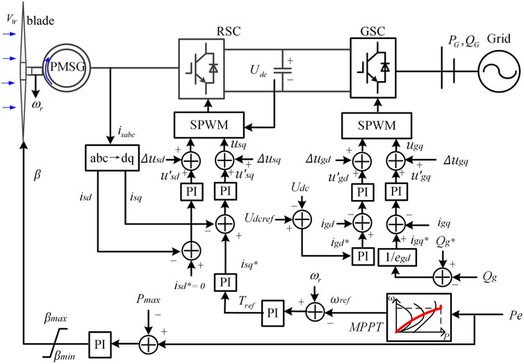
FIGURE 1. Block diagram of a model of the PMSG based wind turbine Generators.
The captured mechanical power from the wind, Pm, is defined by (Sun et al., 2019)
where ρ is air density, R is radius, vw is wind speed, λ is tip speed ratio, λ = ωrR/vw, ωr is rotor speed, β is pitch angle, and Cp(λ,β) is the power coefficient.
As in (Ekanayake and Jenkins, 2004), Cp(λ,β) can be expressed as
A maximum mechanical power rotor speed characteristic curve is pre-defined, and the rotor speed reference is inquired according to the electromagnetic power measurement (Sun et al., 2019). When the wind speed increases, the rotor speed of the WT accelerates due to the increase in the captured power Pm. In order to achieve the balance of the system, the electromagnetic power Pe controlled by the rotor speed controller increases. The increased Pe flows into the DC link capacitor. Then, the GSC injects the active power delivered by the MSC into the power grid to maintain a constant DC link voltage. When the wind speed continues to increase and the electromagnetic power reaches the rated power, the pitch angle control starts to act to ensure that the wind turbine runs at constant power.
However, this type of wind turbine runs in the maximum power tracking mode and cannot respond to the frequency variation of the system. In (LI et al., 2017), a typical frequency regulation scheme that the torque is adjusted according to frequency deviation is proposed, as shown in Figure 2.
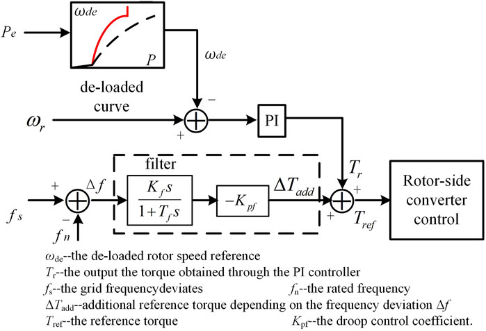
FIGURE 2. Traditional frequency regulation control scheme.
The maximum power tracking control mode is instead of a de-loaded power tracking mode. The de-loaded rotor speed reference, ωde, is provided for the speed controller, and the output of the torque Tr is obtained through the PI controller. When the grid frequency fs deviates from the rated frequency fn, an additional reference torque ΔTadd depending on the frequency deviation Δf is added on Tr. Then, the reference torque Tref is obtained and transmitted to the inner control loop. The captured active power is adjusted by the inner loop response and the rotor speed tracks ωde. Due to the rapid regulation effects of the GSC control system, the GSC and then the active power from MSC are immediately injected into the grid to maintain a constant DC link voltage.
The additional reference torque ΔTadd is determined according to the frequency deviation Δf and the droop control coefficient Kpf, which can be expressed as
However, the additional ΔTadd has a conflict with the speed controller. Tr from the speed controller is used to regulate the rotor speed tracking the reference value. ΔTadd is dependent on the frequency deviation. This conflict influences both speed regulation and frequency support. At the same time, this scheme does not consider the coordination of the torque control and the pitch angle control. In the medium and high wind speed area, pitch angle control is necessary to regulate the active power due to the rotor speed limit. Further, Kpf is a fixed value, which cannot be changed adaptively under different wind speed conditions. When the wind speed is in the low area, the additional reference torque ΔTadd is too large, which causes the rotor speed to drop too fast. When the wind speed is in the high area, the additional reference torque ΔTadd for the frequency regulation will be insufficient.
The Proposed Frequency Regulation Scheme
The Block Diagram of the Proposed Frequency Regulation Scheme
The block diagram of the scheme proposed in this article is shown in Figure 3.
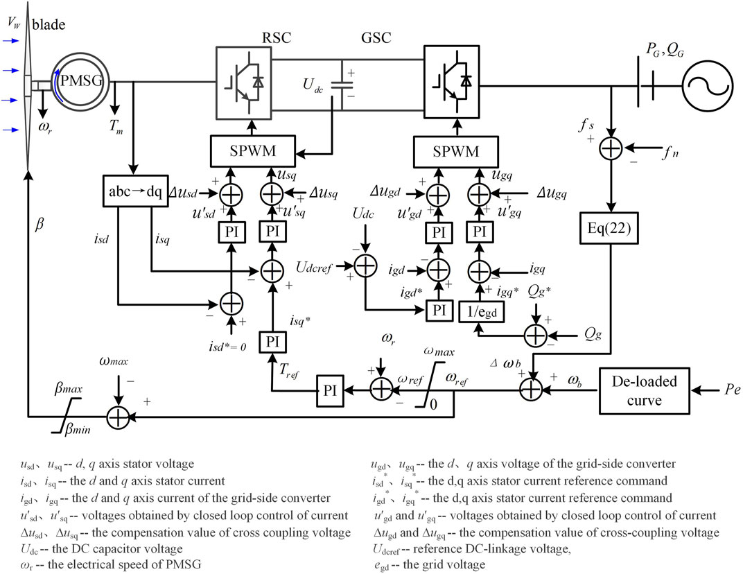
FIGURE 3. The proposed frequency regulation scheme.
To realize the de-loaded control for PMSG during the whole wind speed range, this article defines a new variable, named equivalent rotor speed "ωb" here, which combines the rotor speed and the de-loaded pitch angle.
ωde is de-loaded rotor speed in the low wind speed area and βde is the de-loaded pitch angle in the medium and high wind speed area.
Further, the equivalent rotor speed versus de-loaded power curve is obtained through the wind turbine modeling data fitting. Depending on this curve, the corresponding ωb can be queried according to the electromagnetic power Pe. The detail is given in subsection The Equivalent Rotor Speed-Active Power Curve below.
To directly couple grid frequency with rotor speed, a compensation variable Δωb is obtained based on the frequency deviation. By adding the Δωb on ωb, the reference rotor speed ωref is obtained
Since the equivalent rotor speed ωb contains the sum of the per-unit value of the rotor speed and pitch angle, these two values should be separated to obtain rotor speed reference or pitch angle reference for the controller. Fortunately, pitch angle act only when the rotor speed reaches ωmax (1. p.u in this article). Hence, a limiter is added behind the equivalent rotor speed ωref. When ωref is less than ωmax, ωref is directly used as the reference value of the rotor speed control loop. When ωref is larger than ωmax, the rotor speed reference is ωmax, and the pitch angle reference βref can be obtained by subtracting ωmax from ωref. Hence, the pitch angle can help the de-loaded control and response to frequency variation when ωref exceeds ωmax. How to obtain Δωb is explained in subsection The Calculation Method of the Virtual Compensation Rotor Speed below.
The Equivalent Rotor Speed-Active Power Curve
As in (Zhang et al., 2012), the de-loaded rotor speed and de-loaded pitch angle can be calculated by the following expressions:
where v1 is the cut-in wind speed, v2 is the demarcation point of the wind speed between the low and medium wind speed area, v3 is the demarcation point of the wind speed between the medium and high wind speed area, λopt is the optimal tip speed ratio, and Cp,max is the maximum wind energy capture coefficient. λde is the tip speed ratio when de-loaded ratio is d%, λref is the reference tip speed ratio in overspeed control and, Cp,rated is the wind energy capture coefficient when operating at rated power, β0 is the pitch angle reference when the wind turbines operate at the rated power, βde is the de-loaded pitch angle in the de-loaded control mode, and d% is the de-loaded ratio of the wind turbine. The de-loaded ration d% is given 10% in this article.
In the low wind speed, λopt and Cp,max can be obtained through Eq. 2. Hence, λde can be calculated by Eq. 6, and then we can calculate ωde by λde= ωdeR/v.
In the medium wind area, λref= ωmaxR/v, λopt and Cp,max have been obtained through Eq. 2. The pitch angle (βde) can be calculated through Eq. 6.
In the high wind area, we can calculate Cp,rated by Eq. 1. Then, because λref has been known, β0 can be obtained by Eq. 2. Hence, βde can be obtained by Eq. 6.
Therefore, based on Eq. 4 and Eq. 6, the offline fitting data of the de-loaded power Pde and ωb under different wind speed areas can be obtained. The data and the fitting ωb-Pde curve is shown in Figure 4.
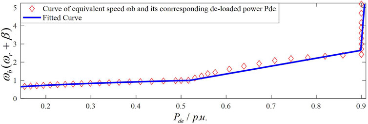
FIGURE 4. The equivalent rotor speed ωb active power Pde curve.
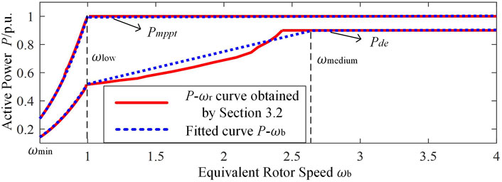
FIGURE 5. The active power equivalent rotor speed ωb curve in the whole wind speed area.
Corresponding to wind speed area, the ωb-Pde curve can be divided into three segments. The first segment is the low wind speed area, where Pde is less than 0.53 p.u. The pitch angle control is disabled; that is, β is 0. According to Eq. 4, ωb is equal to ωde. The second segment is the medium wind speed area, where the power is greater than 0.53 p.u. The third one is the high wind speed area, where Pde is greater than or equal to 0.9 p.u. In the second and the third segments, pitch angle control is enabled.
Considering the accuracy and complexity, the following piecewise function is employed to fit the ωb-Pde curve:
By using the curve fitting tool to perform linear regression on the offline data, the value of each fitting parameter in Eq. 7 can be obtained, which are as follows: k1 = 0.5218; k3 = 0.2393; b3 = 0.29; k4 = 0.003; and b4 = 0.89.
The Calculation Method of the Virtual Compensation Rotor Speed
The virtual compensation rotor speed Δωb is introduced to generate both inertial and primary frequency responses. In Section The Equivalent Rotor Speed-Active Power Curve, Eq. 7 has been obtained, which describes the relationship between the de-loaded power Pde and the equivalent rotor speed ωb. According to the inverse function of Eq. 7, we can obtain the P-ωb curve as in
where ωmin is the cut-in rotor speed of the WT and ωblow is the demarcation equivalent rotor speed between the low wind speed area and the medium wind speed area. The value of ωblow is equal to the rated rotor speed ωmax, which is 1 p.u. ωbmedium is the demarcation equivalent rotor speed between the medium wind speed area and the high wind speed area, and its value is 2.6 p.u. When ωb exceeds ωbmedium, the active power should be kept constant.
The maximum power curve can be approximately is give in
where k2 is the maximum power coefficient, k2 = 0.98.
The Pde-ωb curve and Pmppt-ωb curve in the low wind speed area are given in Figure 6. Assume that PMSG-WTG initially operates at the de-loaded stable point 1′.

FIGURE 6. The active power equivalent rotor speed ωb curve in the low wind speed area.
Generally, the output active power of PMSG is regulated based on the frequency deviation Δf, and its expression is
where ΔPmax is the maximum frequency regulation power, fa and fb correspond to the system frequency regulation interval, and ΔPmax is the limit frequency regulation power.
To prevent the rotor speed lower than the optimal rotor speed during the frequency regulation process, the value of ΔPmax is the difference between the maximum power Pmppt and the de-loaded power with maximum power rotor speed ωb2, that is,
where P2 is the maximum power at operating point ‘2′ and P3 is the de-loaded power with maximum power rotor speed at point ‘3'.
Assuming a frequency dips event occurs, the electromagnetic power Pe should increases, which is equivalent to an increase of the rotor speed Δωb′
Since the rotor speed regulation range is not large, 1>ωb1>>Δωb′. Hence, the higher-order terms with Δωb′ can be ignored, and then Eq. 12 can be simplified
The initial de-loaded power P1 and the maximum power P2 can be expressed as
Then, considering Eq. 8, Eq. 9, and Eq. 15,
From Eq. 16, the following expression can be derived as
Substitute Eq. 17 into Eq. 11, the following expression can be derived:
Further, substitute Eq. 18 into Eq. 10, the following expression is obtained:
Observing Figure 6, Δωb′ is the difference between the equivalent rotor speed of the point ‘1′ and the equivalent rotor speed of the point ‘1'' after the frequency regulation.
In fact, ωb1 is difficult to measure in engineering application. Therefore, ωb1 is replaced with ωb, and Eq. 19 can be written as
ωb is always larger than or equal to ωb1. Hence, by replacing ωb1 with ωb, Δωb is larger and results in releasing more active power.
In the medium wind speed area, since the adjustment range of ωb increases, Δωb' can no longer be ignored. When the frequency dips event occurs, the electromagnetic power can be expressed as
In the high wind speed area, ΔPmax is a constant value, 0.1 p.u.
Using the same analysis approach in the low wind speed area, the relationship between Δωb and Δf in the medium and high wind speed can be derived. The expression of Δωb-Δf can be obtained as
Dynamic Process of Frequency Regulation of the Proposed Control Scheme
The dynamic response of PMSG participating in frequency regulation when the frequency drops is illustrated in Figure 7. The trajectory of active power and rotor speed is shown in Figure 8.
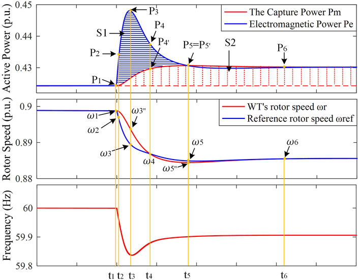
FIGURE 7. The dynamic response process of PMSG participating in frequency regulation.
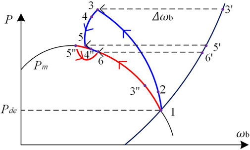
FIGURE 8. The trajectory of active power Pe and the equivalent rotor speed ωb.
In Figure 7, the area of S1 between the mechanical power and the captured power by the wind turbine represents the rotational KE released by the wind turbine. It is mainly used to provide the inertial response and affects the rate of frequency change and frequency nadir. The area of S2 represents the increase in the captured energy by the wind turbine, which is mainly used to provide primary frequency regulation and affect the steady frequency of the system.
The frequency regulation dynamic process is divided into six periods, and the dynamic process in each period is analyzed, respectively.
t < t1: within this time range, Pe is equal to the captured power Pm, the rotor speed remains a constant value, and the PMSG-WTG operates in de-loaded mode.
t1<t < t2: at t = t1, the load suddenly increases and the frequency drops. According to Eq. 22, Δωb decreases. Since the rotor speed of the PMSG decoupled with the grid frequency, the rotor speed ωr remains unchanged at the moment. According to Eq. 7, ωref decreases and the deviation Δωe between ωr and ωref increases. Therefore, through PI control, the electromagnetic torque reference Tref increases. That is, Pe of the PMSG increases. According to the rotor mechanical equation, the rotor speed ωr decreases. Due to ωr decreasing, the capture wind power Pm increases, and its torque Tm also increases.
t2<t < t3: as Pe increases, depending on the Pde-ωb curve, ωb increases. During this period, because Δf is increasing and the change range of ωb is small, Δωb plays a dominant role at this time, so that ωref decreases and its reduction value is larger than the reduction value of ωr. Δωe increases. Therefore, Tref increases after the PI controller, resulting in the increase of Pe. ωr continues to decrease because of the increase of Pe. When t = t3, Δωe reaches the maximum value and Pe reaches the maximum value. Based on the ωb-Pde curve, ωb also reaches its maximum value.
t3<t < t4: during this period, as the frequency starts to recovery, Δωb starts to decrease, and the change of ωref is smaller than the one of ωr, which causes the Δωe to decrease. Pe also begins to decrease, but it is still larger than Pm. ωb also begins to decrease with the decrease of Pe. According to Eq. 7, ωref will decrease. According to the rotor mechanical equation, ωr decreases. t4<t < t5: since Pe is still larger than Pm, according to the rotor mechanical equation, ωr and ωref continue to decrease, and the deviation Δωe continues to decrease, resulting in the decrease of Tref and Pe. As ωr decreases, Pm increases. When t = t5, Pm is equal to Pe for the first time.
t > t5: since the decrease of ωr is slightly slower than ωref, Pm is slightly larger than Pe. Therefore, ωr increases. When t = t6, Pm is equal to Pe and ωr is equal to ωref. At this time, the PMSG-WTG reaches a new steady-state operating point.
Case Study
An islanded microgrid simulation model of wind power-diesel generators is built. The diagram of the islanded microgrid is shown in Figure 9. The rated power of the diesel unit is 70 kW. The nominal RMS voltage and frequency are 5 kV and 50 Hz, respectively.
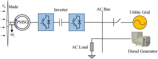
FIGURE 9. The structure diagram of the independent microgrid model.
Various scenarios of wind speed and load changes are set to verify the effectiveness of the proposed frequency regulation scheme. The following three schemes are used to compare with the proposed control scheme.
1) The proposed frequency regulation scheme.
2) The conventional frequency regulation scheme.
3) The variable coefficient control scheme in (Zhu et al., 2021b).
4) The de-loaded control scheme (PMSG does not participate in frequency regulation).
Low Wind Speed Area
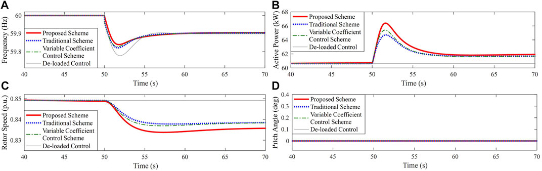
FIGURE 10. Results for Case 1. (A) System frequency; (B) Active power of PMSG; (C) Rotor speed of PMSG; (D) Pitch angle.
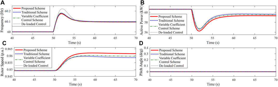
FIGURE 11. Results for Case 2. (A) System frequency; (B) Active power of PMSG; (C) Rotor speed of PMSG; (D) Pitch angle.
Medium Wind Speed Area
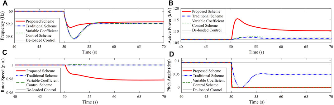
FIGURE 12. Results for Case 3. (A) System frequency; (B) Active power of PMSG; (C) Rotor speed of PMSG; (D) Pitch angle.
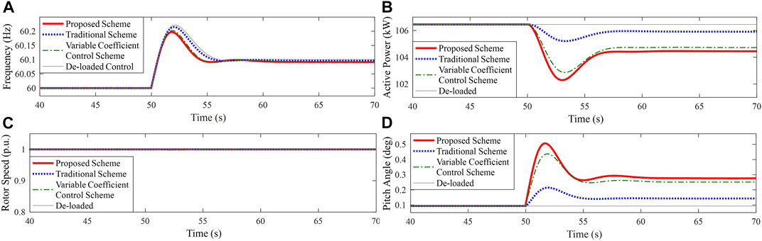
FIGURE 13. Results for Case 4. (A) System frequency; (B) Active power of PMSG; (C) Rotor speed of PMSG; (D) Pitch angle.
High Wind Speed Area
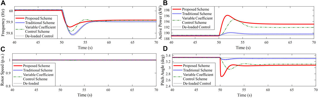
FIGURE 14. Results for Case 5. (A) System frequency; (B) Active power of PMSG; (C) Rotor speed of PMSG; (D) Pitch angle.
Radom Wind Speed
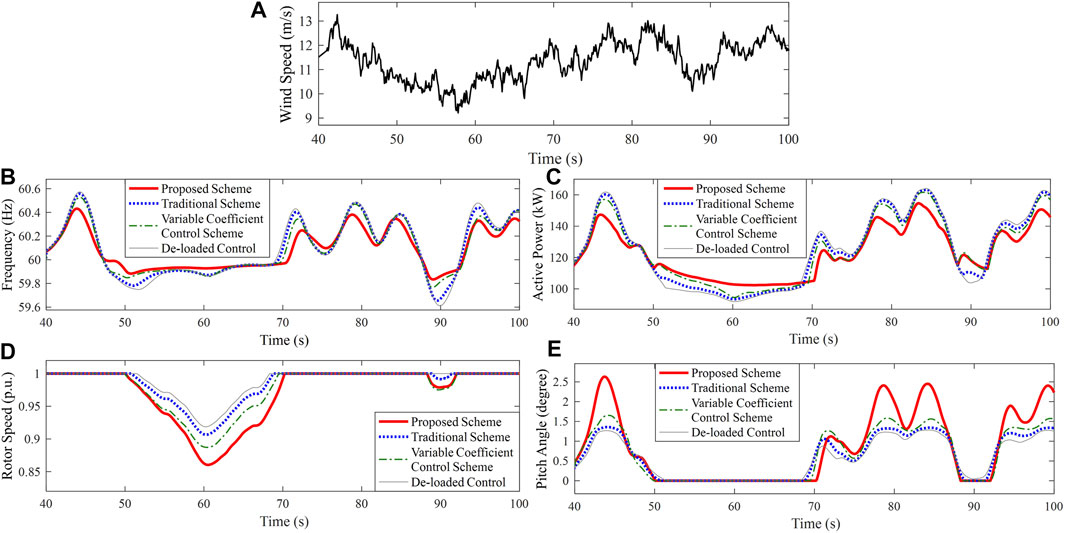
FIGURE 15. Results for Case 6. (A) Random wind speed; (B) System frequency; (C) Active power of PMSG; (D) Rotor speed of PMSG; (E) Pitch angle.
Conclusion
This article proposes an equivalent rotor speed compensation control scheme of PMSG-WTG for frequency support in islanded microgrids. A new equivalent rotor speed variable of combined pitch angle and rotor speed is defined, which can find the rotor speed reference or compensation pitch angle reference according to the active power measurement. As a result, the wind turbine can simply regulate the rotor speed and pitch angle for de-loaded control during the whole wind speed area.
A virtual compensation rotor speed is provided to render PMSG-WTG rotor speed directly coupling grid frequency to generate both the inertial and primary frequency response. The virtual compensation rotor speed adaptively adjusts depending on the frequency deviation to maintain the proper torque comprising of the frequency regulation performance and wind turbine safe operation. Further, the pitch angle and torque are coordinated and regulated to provide frequency support in the medium and high wind speed area.
The simulation results under various conditions show that the proposed scheme has a potential self-adaption and provides adaptive frequency support for the whole wind area.
Data Availability Statement
The original contributions presented in the study are included in the article/supplementary material; further inquiries can be directed to the corresponding author.
Author Contributions
CZ and YL contributed to the conception and design of the study. CZ, YL, and YZ wrote the first draft of the manuscript. HL wrote sections of the manuscript. All authors contributed to manuscript revision and read and approved the submitted version.
Conflict of Interest
Author YZ was employed by State Grid Shandong Electric Power Company.
The remaining authors declare that the research was conducted in the absence of any commercial or financial relationships that could be construed as a potential conflict of interest.
Publisher’s Note
All claims expressed in this article are solely those of the authors and do not necessarily represent those of their affiliated organizations, or those of the publisher, the editors, and the reviewers. Any product that may be evaluated in this article, or claim that may be made by its manufacturer, is not guaranteed or endorsed by the publisher.
References
Adam, Milczarek., Mariusz, Malinowski., and Josep, M. Guerrero. (2015). Reactive Power Management in Islandedmicrogrid-Proportional Power Sharing in Hierarchical Droop Control. IEEE Transa-ctions on Smart Grid. 6 (4), 1631–1637. doi:10.1109/TSG.2015.2396639
Chang-Chien, L.-R., Lin, W.-T., and Yin, Y.-C. (2011). Enhancing Frequency Response Control by DFIGs in the High Wind Penetrated Power Systems. IEEE Trans. Power Syst. 26 (2), 710–718. doi:10.1109/tpwrs.2010.2052402
Chang-Chien, L.-R., Sun, C.-C., and Yeh, Y.-J. (2014). Modeling of Wind Farm Participation in AGC. IEEE Trans. Power Syst. 29 (3), 1204–1211. doi:10.1109/tpwrs.2013.2291397
Ekanayake, J., and Jenkins, N. (2004). Comparison of the Response of Doubly Fed and Fixed-Speed Induction Generator Wind Turbines to Changes in Network Frequency. IEEE Trans. Energ. Convers. 19 (4), 800–802. doi:10.1109/tec.2004.827712
Gao, D. W., Wu, Z., Yan, W., Zhang, H., Yan, S., and Wang, X. (2019). Comprehensive Frequency Regulation Scheme for Permanent Magnet Synchronous Generator‐based Wind Turbine Generation System. IET Renew. Power Generation. 13 (2), 234–244. doi:10.1049/iet-rpg.2018.5247
Hu, J., Wang, S., Tang, W., and Xiong, X. (2017). Full‐Capacity Wind Turbine with Inertial Support by Adjusting Phase‐Locked Loop Response. IET Renew. Power Generation 11 (1), 44–53. doi:10.1049/iet-rpg.2016.0155
Kayikci, M., and Milanovic, J. V. (2009). Dynamic Contribution of DFIG-Based Wind Plants to System Frequency Disturbances. IEEE Trans. Power Syst. 24 (2), 859–867. doi:10.1109/tpwrs.2009.2016062
Lee, J., Jang, G., Muljadi, E., Blaabjerg, F., Chen, Z., and Cheol Kang, Y. (2016). Stable Short-Term Frequency Support Using Adaptive Gains for a DFIG-Based Wind Power Plant. IEEE Trans. Energ. Convers. 31 (3), 1068–1079. doi:10.1109/TEC.2016.2532366
Li, Shichun., Huang, Yuehua., and Wang, Lingyun., (2017). Modeling of Primary Frequency Modulation Auxiliary Control System for Doubly-Fed Wind Turbines Based on Speed Controln. Proc. CSEE 37 (24), 7077–7086.
Li, Xialin., Guo, Li., Wang, Chengshan., and Li, Yunwei. (2016). Overview of Research on Key Technologies of DC Microgrid. Proc. CSEE 36 (1), 2–17.
Liu, T., Pan, W., Quan, R., and Liu, M. (2019). A Variable Droop Frequency Control Strategy for Wind Farms that Considers Optimal Rotor Kinetic Energy. IEEE Access 7, 68636–68645. doi:10.1109/access.2019.2914496
Luo, H., Hu, Z., Zhang, H., and Chen, H. (2019). Coordinated Active Power Control Strategy for Deloaded Wind Turbines to Improve Regulation Performance in AGC. IEEE Trans. Power Syst. 34 (1), 98–108. doi:10.1109/tpwrs.2018.2867232
Margaris, I. D., Papathanassiou, S. A., Hatziargyriou, N. D., Hansen, A. D., and Sorensen, P. (2012). Frequency Control in Autonomous Power Systems with High Wind Power Penetration. IEEE Trans. Sustain. Energ. 3 (2), 189–199. doi:10.1109/tste.2011.2174660
Sun, C., Ali, S. Q., Joos, G., and Bouffard, F. (2019). “Improved VSG Control for Type-IV Wind Turbine Generator Considering Operation Limitations,” in 2019 IEEE Energy Conversion Congress and Exposition (ECCE), 29 Sept.-3 Oct. 2019 (Baltimore, MD, USA: IEEE), 2085–2091. doi:10.1109/ecce.2019.8912663
Tang, X., Yin, M., Shen, C., Xu, Y., Dong, Z. Y., and Zou, Y. (2019). Active Power Control of Wind Turbine Generators via Coordinated Rotor Speed and Pitch Angle Regulation. IEEE Trans. Sustain. Energ. 10 (2), 822–832. doi:10.1109/tste.2018.2848923
Wu, Y.-K., Yang, W.-H., Hu, Y.-L., and Dzung, P. Q. (2019). Frequency Regulation at a Wind Farm Using Time-Varying Inertia and Droop Controls. IEEE Trans. Ind. Applicat. 55 (1), 213–224. doi:10.1109/tia.2018.2868644
Wu, Z., Gao, W., Gao, T., Yan, W., Zhang, H., Yan, S., et al. (2018). State-of-the-art Review on Frequency Response of Wind Power Plants in Power Systems. J. Mod. Power Syst. Clean. Energ. 6 (1), 1–16. doi:10.1007/s40565-017-0315-y
Wu, Z., Gao, W., Wang, X., Kang, M., Hwang, M., Kang, Y. C., et al. (2016). Improved Inertial Control for Permanent Magnet Synchronous Generator Wind Turbine Generators. IET Renew. Power Generation 10 (9), 1366–1373. doi:10.1049/iet-rpg.2016.0125
Zeng, X., Liu, T., Wang, S., Dong, Y., and Chen, Z. (2019). Comprehensive Coordinated Control Strategy of PMSG-Based Wind Turbine for Providing Frequency Regulation Services. IEEE Access 7, 63944–63953. doi:10.1109/access.2019.2915308
Zertek, A., Verbic, G., and Pantos, M. (2012). A Novel Strategy for Variable-Speed Wind Turbines' Participation in Primary Frequency Control. IEEE Trans. Sustain. Energ. 3 (4), 791–799. doi:10.1109/tste.2012.2199773
Zhang, Z.-S., Sun, Y.-Z., Lin, J., and Li, G.-J. (2012). Coordinated Frequency Regulation by Doubly Fed Induction Generator-Based Wind Power Plants. IET Renew. Power Gener. 6 (1), 38–47. doi:10.1049/iet-rpg.2010.0208
Zhao, Jingjing., Li, Min., and He, Xinqin. (2019). Coordinated Control Scheme of Wind Power and Energy Storage in Frequency Regulation Based on Torque Limit Control. Trans. China Electrotechnical Soc. 34 (23), 4982–4990.
Zhao, J., Lv, X., and Fu, Y. (2015). “Wind-solar Diesel Microgrid Frequency Adjustment Technology Based on Variable Coefficient-Based Virtual Inertia and Overspeed Control Coordination of Doubly-Fed Wind Turbines”,. J. Electrotechnical Eng. 30 (5), 59–68. (In Chinese).
Zhao, X., Xue, Y., and Zhang, X.-P. (2020). Fast Frequency Support from Wind Turbine Systems by Arresting Frequency Nadir Close to Settling Frequency. IEEE Open J. Power Energ. 7, 191–202. doi:10.1109/oajpe.2020.2996949
Zhu, Xiaorong., Zheng, Li., and Meng, Fanqi. (2021). Stability Analysis of DC Microgrid Based on Different Grid Structures. Trans. China Electrotechnical Soc. 36 (1), 166–178.
Keywords: the virtual compensation variable of the rotor speed, equivalent rotor speed, PMSG-based wind turbine, de-loaded control, inertial response, frequency support
Citation: Zhong C, Lv Y, Zhou Y and Li H (2021) An Equivalent Rotor Speed Compensation Control of PMSG-Based Wind Turbines for Frequency Support in Islanded Microgrids. Front. Energy Res. 9:717327. doi: 10.3389/fenrg.2021.717327
Received: 30 May 2021; Accepted: 22 July 2021;
Published: 23 August 2021.
Edited by:
Dongdong Zhang, Guangxi University, ChinaReviewed by:
Krishnakumar R. Vasudevan, Universiti Tenaga Nasional, MalaysiaMehdi Firouzi, Islamic Azad University, Abhar, Iran
Copyright © 2021 Zhong, Lv, Zhou and Li. This is an open-access article distributed under the terms of the Creative Commons Attribution License (CC BY). The use, distribution or reproduction in other forums is permitted, provided the original author(s) and the copyright owner(s) are credited and that the original publication in this journal is cited, in accordance with accepted academic practice. No use, distribution or reproduction is permitted which does not comply with these terms.
*Correspondence: Cheng Zhong, emhvbmdjaGVuZ0BuZWVwdS5lZHUuY24=