Corrigendum: Research on Dynamic Equivalent SOC Estimation of Hybrid Energy Storage System Based on Sliding Mode Observer
 Yifei Wang
 Wei Jiang1
 Zhiqi Xu
- 1School of Electrical Engineering, Southeast University, Nanjing, China
- 2Jiangsu Provincial Key Laboratory of Smart Grid Technology and Equipment, Southeast University, Nanjing, China
- 3State Grid Anhui Electric Power Co. Ltd., Tongling Power Supply Company, Tongling, China
This article proposes a sliding mode observer based dynamic equivalent state of charge (ESOC) estimation method for hybrid energy storage system (HESS). Since different types of energy storage components and power electronics circuit are coupled in the HESS, the traditional SOC estimation method cannot reflect the real-time operation characteristics of the HESS. To tackle this problem, a sliding mode observer based on the model of the HESS is built in this article. By collecting the corresponding voltage and current signals, the internal parameters of energy storage elements can be observed accurately in real time. The dynamic ESOC is further defined with the idea of real-time charge balance to reflect the accurate available capacity of the HESS. Finally, the simulation results based on MATLAB/Simulink model are given to verify the feasibility of the proposed dynamic ESOC.
Introduction
Because of the high performance and flexibility of the hybrid energy storage system (HESS), HESS has been widely concerned and studied (Choi et al., 2012; Kim et al., 2015; Akar et al., 2017). The HESS can be applied to applications like motor driving, distributed generation, and backup power (Hammond, 1995; Franquelo et al., 2008; Kouro et al., 2010). The HESS usually consists of two or more types of energy storage components. Battery and supercapacitors are a classic combination. With the high energy density of the battery and the high power density of the supercapacitors, the battery/supercapacitor HESS can provide instantaneous high power output while meeting the capacity demand of the system.
Since the characteristics and parameters of different types of energy storage components vary greatly, power electronic circuits are required in the HESS to couple these components. DC bus-based structure is a common solution (Wang et al., 2014). As a result, unlike the single energy storage technology system, the state of charge (SOC) evaluation of HESS is tricky. The operation mode and power allocation ratio between the components change in real-time according to the need of loads; thus, the dc source of the HESS can be included with either or both of the components. Therefore, neither the SOC of single type of components nor their summation can be simply used as the residual capacity evaluation result of the system.
On the other hand, the SOC is an important factor to be used in the control of the HESS (Xie et al., 2018). Without the accurate estimation of the capacity, the remaining operation time, the power output capability, and the safety of the system cannot be determined.
The SOC evaluation technologies for traditional energy storages have been studied for many years and can be classified into four categories: the open-circuit voltage method, the ampere hour integration method, the neural network method, and the state observation method (He et al., 2012; Lu et al., 2013; Kang et al., 2014).
The open-circuit voltage method is one of the earliest approaches for battery SOC evaluation, which requires experiments’ results to generate the SOC curve. The preparation of open-circuit voltage measurement is tedious. The ampere hour integration method is simple and easy to implant, but the disadvantage is obvious: it needs the accurate initial SOC value of the battery. At present, the open-circuit voltage method and the ampere hour integration method are frequently used in combination due to their complementary functions in practical battery SOC evaluation applications. The neural network method is a novel approach that has received more and more attention in recent years. As a data-driven technology, its parameters can be automatically updated. However, its drawbacks include the overreliance on historical data and computation complexity.
Overall, the above SOC estimation methods mainly aim at the single energy storage technology system. For the HESS, the SOC estimation method must consider not only the nature of the energy storage component, but also the overall operating characteristics of the system. The estimation method requires high real-time performance and accuracy. The state observation method is the method to estimate SOC by establishing a state space model, which has a clear physical meaning, as well as outstanding dynamic performance. The current commonly used methods include the Kalman filter method and the sliding mode observation method. The sliding mode observation method is based on the state space model of the energy storage component. It directly uses the control theory to make the SOC estimation results gradually converge to a specific value. It has the advantages of small calculation, good convergence property, and robustness in the interference environment (II-Song, 2008; II-Song, 2010; Li et al., 2017). The application of sliding mode observation method in SOC estimation has been more and more widely studied. In Gong et al. (2016), the sliding mode observation method is used to estimate the SOC of the battery, and the equivalent circuit model including the uncertain disturbance is established. The reliability of the observer is verified by simulating the constant current discharge and the operation of the electric vehicle. In Chen et al. (2016), a robust sliding mode observer for power battery is built and studied. The radial basis function (RBF) neural network is used to adjust the switch gain of the sliding mode observer, and the target factor recursive least square algorithm is used to identify the parameters of the equivalent model in real time. According to the electrochemical and thermal characteristics of the battery/supercapacitor, a real-time estimation scheme of the state parameters of the energy storage element composed of multiple sliding mode observers is designed in reference Dey et al. (2015). This scheme simulates the internal characteristics of the energy storage element and verifies the convergence of the overall estimation scheme.
To summarize, the sliding mode observation method is more suitable for SOC estimation in HESS, because of its robustness and simple control algorithm. However, it has not been applied on the estimation of SOC of the HESS. The difficulty lies in the coupling between the energy storage components and the power electronics’ circuit in the HESS. Traditionally, the remaining energy of the energy-density component is the basis of the SOC in the HESS. However, the restrictions in the discharging ability and dynamic performance of the energy-density component cannot be reflected in these models, resulting in the overrated SOC.
In this article, a dynamic equivalent SOC (ESOC) index of the HESS is proposed. With the established index, the equivalent SOC can be well reflected. Moreover, the estimation algorithm of the dynamic equivalent index is proposed based on the sliding mode observer. In addition, the models of battery, the supercapacitor, and the DC-DC converter are established to build the observer. The principle of the ESOC is introduced, and an overall dynamic ESOC estimation system is given and verified.
Mathematical Model of the Hybrid Energy Storage System
Battery Cascaded Supercapacitors Hybrid Energy Storage System
Battery cascaded supercapacitors structure is one of the most common topologies for HESS. As shown in Figure 1, the battery bank and the supercapacitors module are coupled with a DC-DC converter. Since the focus of this work is to illustrate the ESOC evaluation principle, the Boost circuit is used in the following analysis. In microgrid related applications, the HESS needs to interface AC bus. Therefore, a DC-AC inverter is connected to the terminal of the supercapacitor.
FIGURE 1
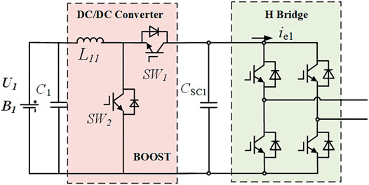
FIGURE 1. The topology of hybrid energy storage system.
In this design, the supercapacitors operate as an energy buffer. It is charged by the battery through DC-DC converter to maintain the DC side voltage of the inverter. In a normal operation, the SOC and the terminal voltage of the supercapacitors keep constant, because their energy can be recovered by the battery in real-time. When high power demand occurs, the supercapacitor can respond quickly and provide an instantaneous output with high climbing rate (Ben et al., 2014; Golchoubian and Azad, 2017). Due to the terminal voltage decline of supercapacitors in high power mode, the operation duration is restrained. When the voltage reaches the lower threshold, the HESS needs to quit the high power mode to recover the energy of the supercapacitors module from battery.
According to the operation principle of the battery cascaded supercapacitors HESS, the working energy storage components in different modes are as follows:
1) Normal operation mode. In this mode, it can be considered that only the battery provides power to the system. The supercapacitor acts as the DC bus buffer. The operation duration in this mode mainly depends on the capacity of the battery.
2) High power mode. In this mode, the battery and the supercapacitor respond to the output at the same time. The power allocation ratio between them usually depends on the frequency characteristics and the peak value of the output. Since the energy is extracted from the supercapacitor faster than that in the normal operation mode, there is not sufficeint time for its terminal voltage to recover from the battery. Therefore, the operation duration in this mode mainly relies on the residual energy of the supercapacitor and the output power it shares.
3) Extreme high power mode. In this mode, the output power share of the supercapacitor is much larger than that of the battery. Since the battery cannot maintain the output of the supercapacitor, the operation duration of the HESS completely depends on the SOC of the supercapacitor.
Thus, at different moment, the energy can be extracted from the HESS, which is determined by the SOC of the battery or/and the supercapacitors, as well as the output power of the system. Meanwhile, the energy recovery speed of the supercapacitors relies on the discharge speed of the battery and the rated power of the DC-DC converter. Therefore, the equivalent models of the two types of energy storage components and the DC-DC converter need to be built and integrated.
Model of the Energy Storage Components
In the HESS studied in this article, the energy-density and power-density energy storage components are the battery and the supercapacitor, respectively. In order to establish the comprehensive model of the HESS for ESOC estimation, the equivalent circuit model of the battery and the supercapacitor should be analyzed first.
As shown in Figure 1, the battery model used in this article is the second-order Thevenin equivalent circuit model, which has been proved to be effective in the static and dynamic characteristics simulation of the battery (Chen and Rincon-Mora, 2006).
In Figure 2, Cn represents the rated capacity of the battery, IB and UB, respectively, represent the terminal voltage and operating current of the battery, Uocv is the ideal open-circuit voltage source, and R0 represents the internal resistance. The parallel RC network is composed of electrochemical polarization capacitor CB1 and resistor RB1, concentration capacitor CB1 and resistor RB1, and concentration polarization capacitor CB2 and resistor RB2, which are used to reflect the short-term and long-term dynamic characteristics of the battery. UB1 and UB2 represent the terminal voltages of the two RC branches.
FIGURE 2
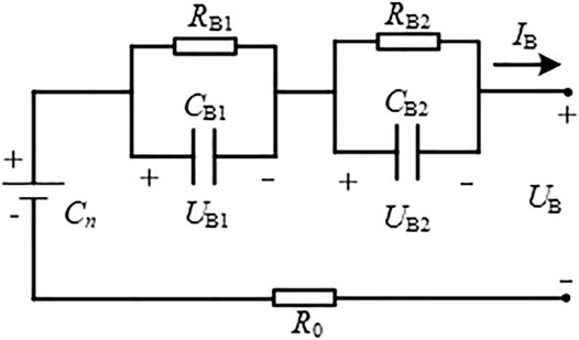
FIGURE 2. The equivalent circuit model of battery.
According to the circuit theory, there are
As a power-density energy storage component, the supercapacitor belongs to the double electric layer capacitor family, whose electrode surfaces are coated with the activated carbon. In this article, an improved second-order RC equivalent circuit model is adopted, which is shown in Figure 2.
The improved second-order RC model simulates the effect of supercapacitor leakage current by adding parallel resistance on the basis of the traditional RC model and reflects the dynamic characteristics of the supercapacitor while ensuring a simple structure (Solano et al., 2013; Graydon et al., 2014). It includes three branches as follows:
1) The branch where RC1 and Csc1 are located is an instantaneous branch, which is used to simulate the instantaneous external characteristics of supercapacitor under the state of charging and discharging, and its time constant is small. Usc1 is its terminal voltage.
2) The branch where RC2 and Csc2 are located is the self-adjusting branch, which reflects the internal of the supercapacitor charging redistribution. Usc2 is its terminal voltage.
3) The branch where RL is located is the self-discharge branch, which is used to represent the self-discharge phenomenon of the supercapacitor. RP is the additional internal resistance. IC and Uout represent the operating current and output voltage during the charging and discharging of the supercapacitor, respectively.
According to the Figure 3, there are
FIGURE 3
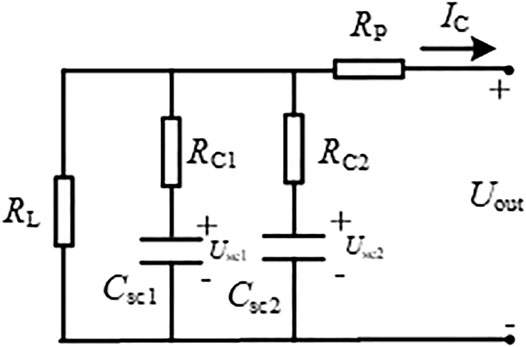
FIGURE 3. The equivalent circuit model of Supercapacitor.
The above models will be integrated into the comprehensive model of the HESS. Meanwhile, their internal components will be selected as the state variables of the sliding mode observer to estimate the remaining energy of the battery and the supercapacitor.
Equivalent Model of the Hybrid Energy Storage System
According to the equivalent circuit model of the energy storage components and the Boost converter, the comprehensive model of the battery cascaded supercapacitors HESS is established as shown in Figure 4.
FIGURE 4
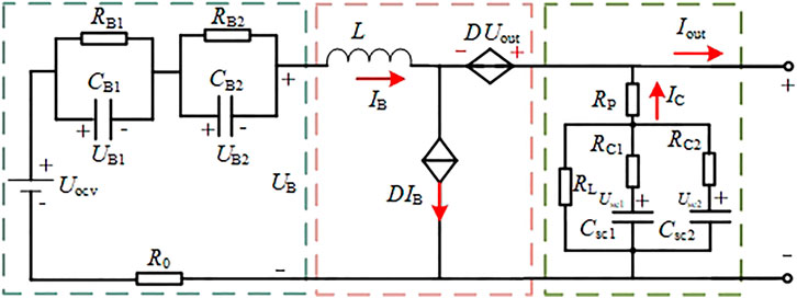
FIGURE 4. The internal structure diagram of the HESS.
The large signal circuit model consists of controlled voltage and current sources used to represent the dynamic characteristics of the boost converter. (Chen et al., 2004). In Figure 4, D represents the duty cycle of the switching device, so the input and output voltage of the converter are as follows:
The state space model of the HESS reflects the relationship of the internal voltage and current signals, which is the basis for the sliding mode observer. Based on the internal structure diagram of the HESS, the output voltage of the energy storage system Uout, the terminal voltages of the ideal voltage source and two polarization capacitances of the battery model Uocv, UB1 and UB2, and the terminal voltages of the two branch capacitances of the supercapacitor model Usc1 and Usc2 are taken as the state variables x. There is
The sampled output currents of the system and the supercapacitor compose the input vector
Based on Eqs. 1–3, Eqs. 4–6 and Eq. 7), the state space model of hybrid energy storage system is given as follows:
where a11 = −1/RB0CB1, a12 = −(1/RB1CB1+1/R0CB1), a21 = −1/RB0CB2, a22 = −(1/RB2CB2 + 1/R0CB2), a31 = −1/RC1Csc1, a41 = −1/RC2Csc2.
When the state space model is given, the ESOC estimator needs the accurate voltage and current signals in the equivalent circuit model of energy storage elements, which will be achieved with the sliding mode observer.
Design of Sliding Mode Observer
The sliding mode observer is a nonlinear observer that obtains the estimated values of the state variables through the measured input and output values of the system. The sum of the input and the negative feedback of the output can force the system to move along a specific state curve with small and high frequency steps, which is defined as the sliding motion. Finally, the state estimation value will approach a hyperplane. Therefore, the error between the estimated output and the actual value approaches zero, so as to realize the accurate estimation of the state variables.
The sliding mode observer is based on the Luenberger observer. Its structure can be expressed as follows:
where x is the state variable, u is the input variable, and y is the output variable. A and B are the system matrix and input matrix, respectively. K is the constant of the feedback correction, which is used to make the system stable, and e is the error between the observed value and the actual measured value of the state. The function M is the control variable of the sliding mode observer. When the output error is not zero, the variable is used to make the system move along the sliding mode surface at a high frequency.
The premise that the sliding mode observer can estimate the internal energy storage elements of the energy storage system is that the matrix system is observable (Gong et al., 2016). The observability matrix of the nonlinear system is expressed as
According to Eq. 9 and Eq. 10, it can be easily proven that Ob is full rank. Therefore, the system is observable; that is, the observer can be used to observe the parameters of the HESS.
By adapting the Walcott–Zak observer (Chang and Zheng, 2015), the sliding mode observer of the HESS is established:
where
If the sliding surface s = eB is defined, the state equation of error is
where d1−d6 is used to simulate the influence of system noise.
According to the requirements of Lyapunov stability function, it is necessary to ensure that the difference value of each voltage of the state variable approaches 0. Take Uout as an example. If the system is stable on the sliding surface, it needs to meet the following requirements:
According to Eq. 15, if Eq. 16 stands, the feedback gain Lout should satisfy
Assuming that the estimated terminal voltage gradually stabilizes in a certain period of time and finally reaches the sliding mode surface, that is,
Considering the observation of UB2 and Uocv, the following formula stands:
Then, the observation of UC1 and UC2 inside the supercapacitor is analyzed. According to the requirements of Lyapunov stability function, its feedback gain meets the following formulas:
According to the above analysis, if the designed sliding mode observer can realize the accurate estimation of relevant parameters, and Lout、LB1、LB2、Locv、LC1 and LC2 need to meet the requirements of Eqs. 17–22. In the practical design, because the above feedback gains are only constrained by the minimum value, the error value in the formula can be considered as the extreme value. Through the reasonable selection of Lout、LB1、LB2、Locv、LC1 and LC2, the state variables in the HESS can be accurately estimated by using the sliding mode observer.
The Estimation of Dynamic Equivalent State of Charge
First, we introduce the proposed estimation System of the dynamic ESOC. The complete estimation system of the ESOCD is based on sliding mode observer and shown in Figure 5. The output voltage Uout, current Iout and supercapacitor branch current IC of the DC side are collected in each TSOC. Based on the sliding mode observer defined in Eq. 13, the observed values of
FIGURE 5
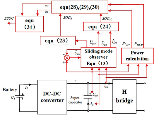
FIGURE 5. Estimation system of the dynamic ESOC.
At the same time, the average values of PB_av and Pout_av are generated from the collected voltage and current. Consequently, Eq. 28, Eq. 29, and Eq. 30 are used to obtain the weighting coefficients α1 and α2 for Eq. 31 to finally calculate the ESOCD. With this design, the estimation of the dynamic ESOCD can be realized with the available voltage and current signals.
According to the above analysis, the voltage of ideal voltage source UOCV and the capacitance voltages UC1 and UC2 of the two branches of the supercapacitor in the state space equation of the HESS can be accurately estimated with the sliding mode observer. Considering that the observed value of UOCV has a nonlinear function relationship with the SOC of battery, which can be obtained through experiments, the specific method is to measure the UOCV of the battery after a period of continuous discharge with a fixed current value. The SOC at the corresponding time can be obtained by simple integral calculation. After several experiments, UOCV and SOC value data can be synthesized into a curve by the least square method. In this article, they can be calculated by the following Eq. 25:
where K0−K2 are the experimental constants.
According to the definition of SOC, that is, the ratio of residual capacity to rated capacity, the SOC of supercapacitor can be defined as
where UC1N and UC2N are rated voltages of capacitors CSC1 and CSC2.
As aforementioned, for the HESS, which is composed of battery and supercapacitor, its SOC cannot be defined as the sum of the remaining capacity of the two energy storage components and the total capacity of the system. Since the energy-density of the battery is far larger than that of the supercapacitors, the sum of their remaining capacity will mainly represent the SOC of the battery. However, in high power and extreme high power operation modes, the capacity of the battery cannot be utilized because of its discharge speed. In these modes, the SOC of the HESS is determined by the supercapacitors.
Therefore, the ESOC of the HESS needs to be evaluated dynamically according to the real-time operation mode of the system. In this work, the dynamic ESOC ESOCD is defined with two weighting coefficients α1 and α2, which change with the real-time operation mode:
ESOCD is estimated in every time period TSOC. With the proposed sliding mode observer, the average output powers PB_av and Pout_av of the battery and the system can be obtained based on the real-time detected Uout, IC and Iout in TSOC:
The SOC lower and upper thresholds of battery and supercapacitor are defined as (SOCBmin, SOCBmax) and (SOCSCmin, SOCSCmax), respectively. Nt1 and Nt2 are defined as the number of time periods that two kinds of energy storage components can continue to operate with the current output power:
where EBN and ESCN, respectively, represent the rated capacity of battery and supercapacitor.
Therefore, Nt1 and Nt2 dynamically change with time and reflect the duration of continuous operation of the two kinds of energy storage components in real time. In order to ensure that the SOCs of energy storage components are restricted within the threshold range, the weighting coefficients are further designed as the reciprocal value of Nt1 and Nt2:
The physical meaning of α1 and α2 is the ratio of the energy consumed by the battery and supercapacitor to their respective residual capacity in the current time of TSOC. With this design, the corresponding weighting coefficient of the energy storage component with long operation duration will be relatively small, and that of the one with short duration will be relatively large. The greater the operation duration difference, the greater the weight coefficient difference, so that ESOCD can reflect the residual operation duration of the HESS according to its operation mode. For example, with extreme high power output mode, although the SOCB is high, since PB_av is low, α1 will be a small number. Therefore, the effective proportion of SOCB in ESOCD will be small.
Denote m = α2/α1, and then the dynamic ESOCD can be expressed as
In Equation 31, since both values of the SOCB and SOCsc are between 0 and 1, the calculated ESOCD value will be between 0 and 1. According to Eq. 31, there is
It can be seen from Eq. 32 that the upper and lower limits of ESOCD will not exceed those of the battery and supercapacitor. By defining the ESOCD, the real-time estimation of output power and SOCs of the battery and supercapacitors can be used to accurately determine the residual operation duration of the HESS in the current conditions.
Simulation Results
In order to verify the effectiveness of the designed sliding mode observer in SOC estimation, a simulation model is built based on the MATLAB/Simulink platform. The model is based on the HESS model in Figure 1, while an adjustable resistive load is connected to the output of the DC-AC inverter to change the output power of the system. The simulation parameters are shown in Table 1.
TABLE 1
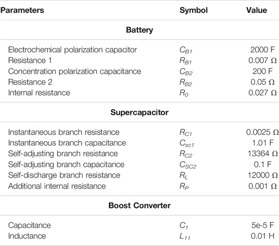
TABLE 1. Simulation parameters.
According to the simulation model, considering the corresponding accuracy requirements of the sliding mode observer, the parameters are selected as follows: Lout = 100, LB1 = 21, LB2 = 12, Locv = 0.01, LC1 = 1 and LC2 = 1. In order to intuitively reflect the real-time observation effect of sliding mode observer on the battery and supercapacitor, the HESS is considered in the high-power working mode. For comparison, when the basic output characteristics are the same, the existing battery and supercapacitor models in Simulink are also used at the same time, and the value of SOC, which is measured directly, is taken as the actual value.
In the high-power operation mode, the battery and the supercapacitor provide power to the load at the same time, and the SOC of the two energy storage components changes in real-time according to their outputs. Figures 6A,B are the actual and estimated values of the SOC of the battery in operation, while Figures 7A,B show those of the supercapacitor. From Figures 6,7, it can be seen that the actual value is basically consistent with the estimated value.
FIGURE 6
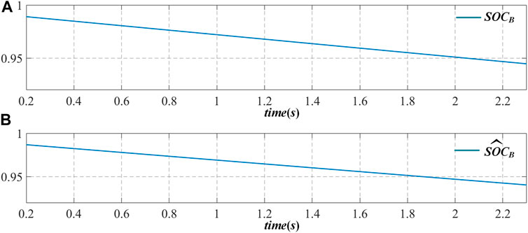
FIGURE 6. Schematic diagram of SOC actual value and estimated value change of battery in high power mode.
FIGURE 7
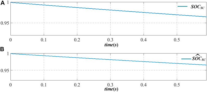
FIGURE 7. Schematic diagram of SOC actual value and estimated value change of supercapacitor in high power mode.
The error between them is within 0.02, which proves the accuracy of SOC estimation based on sliding mode observer proposed in this article.
According to the definition of ESOCD in Eq. 31, the simulation model is established to analyze its effectiveness. The max–min ranges of the energy storage components are, respectively, set as (SOCBmin, SOCBmax) = (0.4, 1), (SOCSCmin, SOCSCmax) = (0.6, 1), PBmax = 324 w, PSCmax = 3 KW, EB = 1 Ah. The initial SOC of the battery is set to 0.69. The supercapacitor capacity CSC is 3 F. The experiments are designed in three modes.
In the normal operation mode, the supercapacitor is not involved in providing energy and the output power of the battery PB1 = 240 W. In the high power mode, the battery and the supercapacitor supply power to the system at the same time. The output power of the battery PB2 = 300 W, and the output power of the supercapacitor PSC1 = 1100 W. In the extreme high power mode, the output of the supercapacitor occupies the main power output, and PSC2 = 2000 W.
Figure 8 shows the changes of the SOC of the battery SOCB, the SOC of the supercapacitor SOCSC, and two sets of ESOC values in different mode. Except the proposed ESOCD, the EOSCs is defined as
FIGURE 8
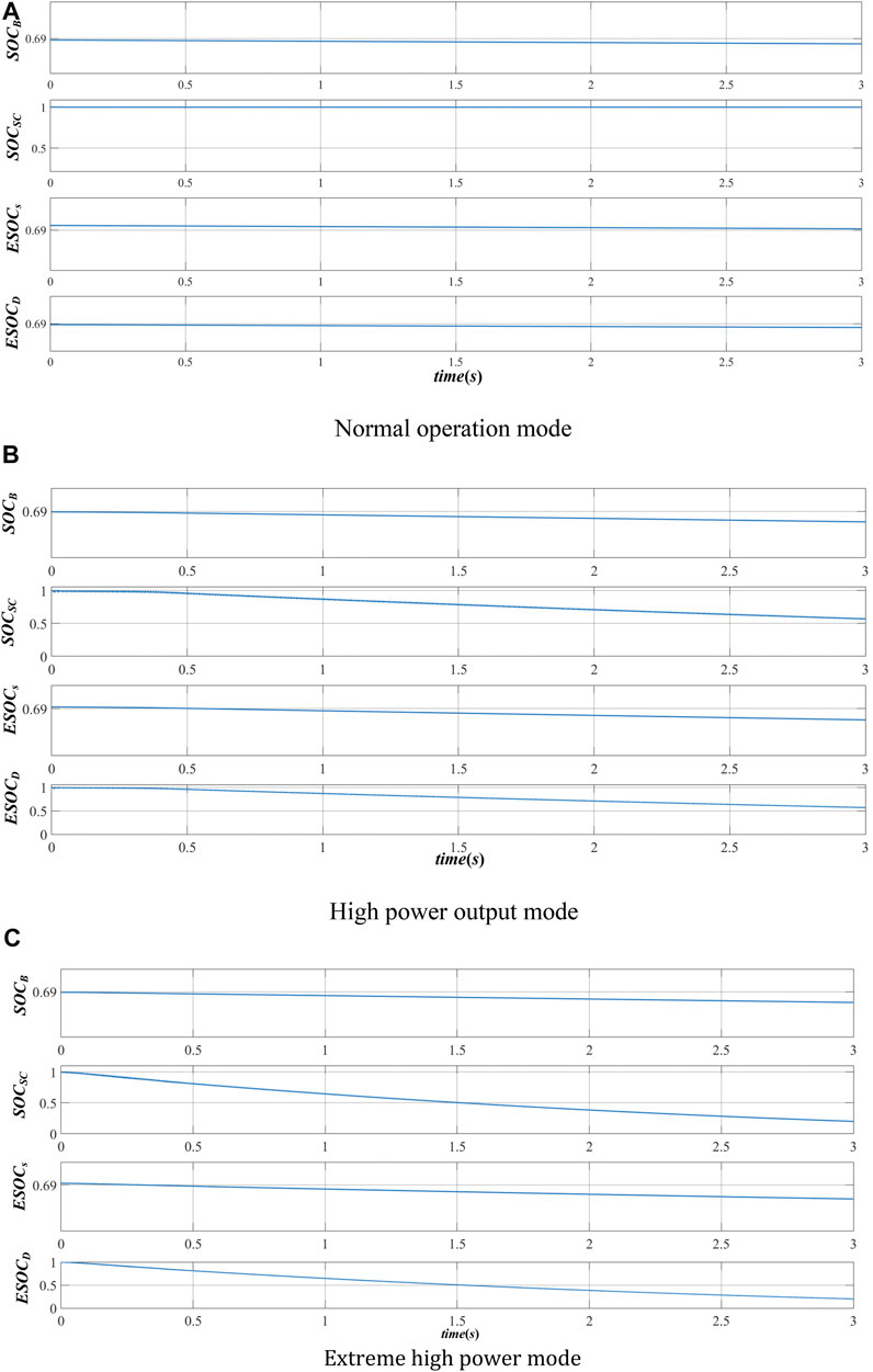
FIGURE 8. Schematic diagram of SOCB, SOCSC, ESOCs, and ESOCD changes.
EOSCs mainly reflects the direct definition of the ESOC of HESS by calculating the residual capacity of all energy storage elements. In this work, EOSCs is used for comparison.
Figure 8A shows that, in the normal operation mode, SOCSC keeps constant. The ESOCD follows SOCB. Figure 8B shows that, in the high power mode, the SOCSC starts to decline from the initial time, since its power cannot be recovered from the battery. Therefore, the change trend of ESOCD is consistent with that of the supercapacitor. In this process, although the SOCB of the battery drops faster than that in Figure 8A, ESOCD is mainly affected by the supercapacitor. Figure 8C shows the change of SOCs in the extreme high power mode. It can be seen that the SOCSC drops more rapidly, which drops to about 0.3 within 3S. At this time, the change trend of ESOCD is almost the same as SOCSC. The influence of SOCB on ESOCD can be ignored.
As the ESOCs reflects the residual capacity of the HESS, it can be seen from Figure 8 that the change of ESOCs in the three modes is consistent with SOCB. It is obvious that the residual energy of the HESS cannot reflect the remaining operation duration. If the real-time equivalent SOC index is not properly defined and used, the overcharge and overdischarge of energy storage components will occur, which will reduce the safety and reliability of the system.
Conclusion
A sliding mode observer based dynamic ESOC estimation method for HESS is proposed in this article. By analyzing the topological structure of the HESS and the equivalent circuit model of the energy storage elements, the corresponding sliding mode observer is established by using the state space model. The parameters of the sliding mode observer are designed to realize the real-time and accurate estimation of the internal parameters of the HESS. In view of the high coupling of different types of energy storage elements, the concept of dynamic ESOC is proposed. Using the real-time acquisition value and estimation value, the remaining working time of energy storage elements is taken as the comparison way, so that ESOC can evaluate the working state of the whole energy storage system. The simulation results further verify the accuracy and real-time performance of SOC estimation based on sliding mode observer, as well as the effectiveness of dynamic ESOC evaluation.
Data Availability Statement
The original contributions presented in the study are included in the article/Supplementary Material. Further inquiries can be directed to the corresponding author.
Authors’ Contributions
YW did the modeling and writing. WJ provided the technical support. CZ performed running case studies. ZX and YD helped modify the article.
Funding
This paper is supported by National Natural Science Foundation of China (51877041), Basic Research Program of Jiangsu Province (BK20200385), Guangdong Basic and Applied Basic Research Foundation (2020A1515011160) and the foundation of Jiangsu Provincial Key Laboratory of Smart Grid Technology and Equipment, Southeast University.
Conflict of Interest
Author CZ was employed by Tongling Power Supply Company.
The remaining authors declare that the research was conducted in the absence of any commercial or financial relationships that could be construed as a potential conflict of interest.
Publisher’s Note
All claims expressed in this article are solely those of the authors and do not necessarily represent those of their affiliated organizations, or those of the publisher, the editors, and the reviewers. Any product that may be evaluated in this article, or claim that may be made by its manufacturer, is not guaranteed or endorsed by the publisher.
References
Akar, F., Tavlasoglu, Y., and Vural, B. (2017). An Energy Management Strategy for a Concept Battery/Ultracapacitor Electric Vehicle with Improved Battery Life. IEEE Trans. Transp. Electrific. 3 (1), 191–200. doi:10.1109/tte.2016.2638640
Ben, I. S., Bayoudhi, B., and Diallo, D. (2014). EV energy management strategy based on a single converter fed by a hybrid battery/supercapacitor power source. Tunisia: Sfax, 246–250.2014 First International Conference on Green Energy ICGE 2014
Chang, F., and Zheng, Z. (2015). An SOC estimation method based on sliding mode observer and the Nernst Equation. Montreal: IEEE Energy Conversion Congress and Exposition (ECCE), 6187–6190. QC, 2015.
Chen, M., and Rincon-Mora, G. A. (2006). Accurate electrical battery model capable of predicting runtime and I-V performance. IEEE Trans. Energ. Convers. 21 (2), 504–511. doi:10.1109/tec.2006.874229
Chen, X., Shen, W., Dai, M., Cao, Z., Jin, J., and Kapoor, A. (2016). Robust Adaptive Sliding-Mode Observer Using RBF Neural Network for Lithium-Ion Battery State of Charge Estimation in Electric Vehicles. IEEE Trans. Veh. Technol. 65 (4), 1936–1947. doi:10.1109/tvt.2015.2427659
Chen, Y. F., Qiu, S. S., and Long, M. (2004). Nonlinear large-signal modeling of PWM DC-DC switching power converters, 2004 International Conference on Communications, 2. Chengdu: Circuits and Systems (IEEE Cat. No.04EX914), 1507–1510.
Choi, M.-E., Kim, S.-W., and Seo, S.-W. (2012). Energy Management Optimization in a Battery/Supercapacitor Hybrid Energy Storage System. IEEE Trans. Smart Grid 3 (1), 463–472. doi:10.1109/tsg.2011.2164816
Dey, S., Mohon, S., Pisu, P., Ayalew, B., and Onori, S. (2015). Online state and parameter estimation of Battery-Double Layer Capacitor Hybrid Energy Storage System, 2015 54th IEEE Conference on Decision and Control. Osaka: CDC, 676–681.
Franquelo, L., Rodriguez, J., Leon, J., Kouro, S., Portillo, R., and Prats, M. (2008). The age of multilevel converters arrives. EEE Ind. Electron. Mag. 2 (2), 28–39. doi:10.1109/mie.2008.923519
Golchoubian, P., and Azad, N. L. (2017). Real-Time Nonlinear Model Predictive Control of a Battery-Supercapacitor Hybrid Energy Storage System in Electric Vehicles. IEEE Trans. Veh. Technol. 66 (11), 9678–9688. doi:10.1109/tvt.2017.2725307
Gong, X., Huang, Z., Li, L., Lu, H., Liu, S., and Wu, Z. (2016). A new state of charge estimation for lithium-ion battery based on sliding-mode observer and battery status, 2016 35th Chinese Control Conference. Chengdu: CCC, 8693–8697.
Graydon, J. W., Panjehshahi, M., and Kirk, D. W. (2014). Charge redistribution and ionic mobility in the micropores of supercapacitors. J. Power Sourc. 245, 822–829. doi:10.1016/j.jpowsour.2013.07.036
Hammond, P. W. (1995). A new approach to enhance power quality for medium voltage drives. Denver, CO, USA: Industry Applications Society 42nd Annual Petroleum and Chemical Industry Conference, 231–235.
He, H., Zhang, X., Xiong, R., Xu, Y., and Guo, H. (2012). Online model-based estimation of state-of-charge and open-circuit voltage of lithium-ion batteries in electric vehicles. Energy 39 (1), 310–318. doi:10.1016/j.energy.2012.01.009
II-Song, K. (2010). A Technique for Estimating the State of Health of Lithium Batteries through a Dual-Sliding-Mode Observer. IEEE Trans. Power Elect. 25 (4), 1013–1022.
II-Song, K. (2008). Nonlinear State of Charge Estimator for Hybrid Electric Vehicle Battery. IEEE Trans. Power Elect. 23 (4), 2027–2034.
Kang, L., Zhao, X., and Ma, J. (2014). A new neural network model for the state-of-charge estimation in the battery degradation process. Appl. Energ. 121 (5), 20–27. doi:10.1016/j.apenergy.2014.01.066
Kim, S.-T., Bae, S., Kang, Y. C., and Park, J.-W. (2015). Energy Management Based on the Photovoltaic HPCS with an Energy Storage Device. IEEE Trans. Ind. Electron. 62 (7), 4608–4617. doi:10.1109/tie.2014.2370941
Kouro, S., Malinowski, M., Gopakumar, K., Pou, J., Franquelo, L. G., Bin Wu, B., et al. (2010). Recent advances and industrial applications of multilevel converters. IEEE Trans. Ind. Electron. 57 (8), 2553–2580. doi:10.1109/tie.2010.2049719
Li, W., Liang, L., Liu, W., and Wu, X. (2017). State of Charge Estimation of Lithium-Ion Batteries Using a Discrete-Time Nonlinear Observer. IEEE Trans. Ind. Electron. 64 (11), 8557–8565. doi:10.1109/tie.2017.2703685
Lu, L., Han, X., Li, J., Hua, J., and Ouyang, M. (2013). A review on the key issues for lithium-ion battery management in electric vehicles. J. Power Sourc. 226 (3), 272–288. doi:10.1016/j.jpowsour.2012.10.060
Solano, J., Hissel, D., and P'era, M. C. (2013). Modeling and parameter identification of ultracapacitors for hybrid electrical vehicles. Proc. IEEE 9th Veh. Power Propul. Conf., 1–4.
Wang, C., Li, X., Guo, L., and Li, Y. W. (2014). A Nonlinear-Disturbance-Observer-Based DC-Bus Voltage Control for a Hybrid AC/DC Microgrid. IEEE Trans. Power Elect. 29 (1), 6162–6177. doi:10.1109/tpel.2013.2297376
Keywords: hybrid energy storage system, sliding mode observer, dynamic ESOC, SOC estimation, real-time charge balance
Citation: Wang Y, Jiang W, Zhu C, Xu Z and Deng Y (2021) Research on Dynamic Equivalent SOC Estimation of Hybrid Energy Storage System Based on Sliding Mode Observer. Front. Energy Res. 9:711716. doi: 10.3389/fenrg.2021.711716
Received: 19 May 2021; Accepted: 23 July 2021;
Published: 23 August 2021.
Edited by:
Yingjun Wu, Hohai University, ChinaCopyright © 2021 Wang, Jiang, Zhu, Xu and Deng. This is an open-access article distributed under the terms of the Creative Commons Attribution License (CC BY). The use, distribution or reproduction in other forums is permitted, provided the original author(s) and the copyright owner(s) are credited and that the original publication in this journal is cited, in accordance with accepted academic practice. No use, distribution or reproduction is permitted which does not comply with these terms.
*Correspondence: Yifei Wang, wyf@seu.edu.cn