- 1State Key Laboratory of Intense Pulsed Radiation Simulation and Effect (Northwest Institute of Nuclear Technology), Xi’an, China
- 2Xi’an High Technology Institute, Xi’an, China
In order to study the feasibility of the fast periodic pulsed reactor with UO2 as fuel (abbreviated as FPPRU), the core models with different load schemes are designed. Neutronic characteristics of two typical design schemes are compared, and the better design scheme is determined. The critical search method is established for analyzing the reactor dynamics. Furthermore, the theoretical estimation formulas are derived to study the factors affecting the reactor dynamics clearly and intuitively. The reactor dynamics of the fast periodic pulsed reactor with UO2 and PuO2 as fuel are compared. The thermal hydraulic characteristic of FPPRU is studied with the sub-channel model. The results show that the design scheme of the FPPRU meets the demand of neutronics and thermal hydraulics safety. Meanwhile, the pulse parameter quality of the FPPRU with UO2 as fuel is not as good as that of IBR-2 with PuO2 as fuel.
Introduction
The fast periodic pulsed reactor uses rotating reflectors to introduce periodic reactivity, making the core generate power pulses at a certain frequency. The fast periodic pulsed reactor IBR-2 had been built in 1984 in the Joint Institute for Nuclear Research of Russia and had retired in 2006. And then the modernized reactor IBR-2M was designed and built and was put into use in 2011 (Dragunov et al., 2012). After successful operation for as long as 37 years, the fast periodic pulsed reactor IBR-2/IBR-2M has been proven to be safe. IBR-2/IBR-2M could provide pulsed neutron flux with narrow half-width and high intensity. Lots of research has been carried out in a wide range of scientific fields, including condensed physics, biology, chemistry, material, geophysics, new superconductivity, and heavy metal nuclear database (Marina, 2011; Ata-Allah et al., 2016; Avdeev et al., 2019; Badawy et al., 2020; Golovin et al., 2020; Turchenko et al., 2020).
So far, lots of studies are performed on many aspects of IBR-2/IBR-2M, such as operation lifetime, neutron flux, reactor dynamics, and reactor safety. For example, in order to increase the operation lifetime of IBR-2M, in 2020, Ananiev studied the way to optimize the reactor fuel run by reshuffling fuel assemblies, giving more uniform fuel burn up and increasing the core lifetime by almost 1/4 (Ananiev et al., 2020). For improving the neutron flux, in 2018, Ananiev considered the neutronic aspect of the IBR-2 reactor optimization and studied the way to increase the thermal neutron flux theoretically (Ananiev et al., 2019). In 2013, Kulikov studied the way to optimize the cold-neutron yield and found the best material for use in IBR-2M cold moderators (Kulikov and Shabalin, 2013). The reactor dynamics plays a very important role in the operation and safety of this kind of reactor. In 2017, Pepelyshev analyzed the transient processes caused by intentional periodic oscillations of the reactivity and investigated the fast feedback parameters of IBR-2M (Pepelyshev et al., 2017). In 2015, Pepelyshev simulated the transitional processes at a wide range of reactivity change and power change, and the result is in good accordance with the detected one (Pepelyshev et al., 2015). In 2010, Chan and Pepelyshev studied the IBR-2 dynamics with power shedding (Chan and Pepelyshev, 2010). In 2008, Chan and Pepelyshev studied the power feedback dynamics taking account of slow components (Chan and Pepelyshev, 2008). In 2006, Pepelyshev analyzed the power pulse shape measured over the entire dynamic range of neutron flux variation and found out how to obtain best approximation to the experimental data (Pepelyshev and Popov, 2006a). And Pepelyshev successfully used the dynamical method to determine the reactivity effects of two types of moving reflectors in the pulsed regime of IBR-2 reactor operating at power (Pepelyshev and Popov, 2006b). For the modernization from IBR-2 to IBR-2M, Dragunov introduced the project modernizing the reactor and the technical characteristics before and after modernization (Dragunov et al., 2012). For the safety of IBR-2, in 2010, Pepelyshev discussed the safety and reliability of the reactor and showed how a series of safety problems related to IBR-2 reactor physics are resolved (Pepelyshev et al., 2010).
Till now, almost all the research studies aimed at the IBR-2 type reactor with PuO2 as fuel. As UO2 fuel is very widely used in nuclear reactors, the use of UO2 may promote the development of the fast periodic pulsed reactor. The study on the feasibility of such reactor using UO2 fuel is very meaningful. The fast periodic pulsed reactor with UO2 fuel (abbreviated as FPPRU) is designed in this article. And the feasibility is studied from the view of neutronics, dynamics, thermal hydraulics, and so on.
Methods and Results
Conceptual Design of the FPPRU
Brief Description of IBR-2M
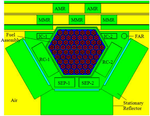
As the conceptual design of the fast periodic pulsed reactor with UO2 as fuel is on the basis of IBR-2M, the structure of IBR-2M is briefly introduced here. As shown in Figure 1, the IBR-2M core is of an irregular hexagonal shape consisting of 69 PuO2 fuel assemblies and is cooled by liquid sodium. Outside the core, there are two kinds of reflectors. One is the stationary reflector and the other is the moving reflector, which consists of one main moving reflector (MMR in Figure 1) and one auxiliary moving reflector (AMR in Figure 1). Seven control rods are used to regulate the reactivity, including two regulating rods (IC-1 and IC-2 in Figure 1), two compensating rods (RC-1 and RC-2 in Figure 1), two safety rods (SEP-1 and SEP-2 in Figure 1), and one fine adjusting rod (FAR in Figure 1). The material of all the reflectors and control rods is stainless steel. MMR and AMR are located on one side, opposite the core. The unique feature of the reactor is that it controls the periodic change of reactivity through the movable reflectors MMR and AMR outside the reactor and generates continuous pulses at a certain frequency. The rotating speeds of MMR and AMR are 600r/min and 300r/min, respectively, and the rotating directions are opposite. At a period of 200 ms, the two reflectors pass simultaneously opposite the core. At the very moment, the combination of the two reflectors could cover the neutron flight direction toward the core's periphery, and the core changes from deep subcritical state to transient supercritical state, generating continuous power pulses at a frequency of 5 Hz. The average thermal power and peak pulse power are 2 and 1500 MW, respectively.
Design Schemes of the FPPRU
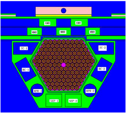
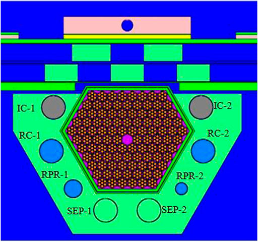
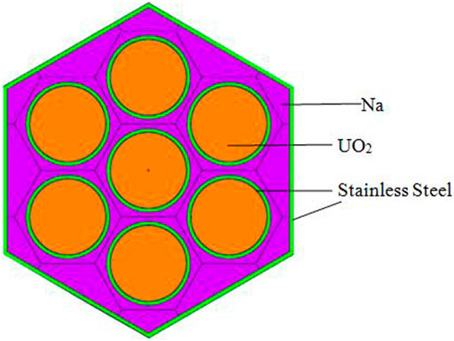
In this article, different conceptual design schemes for the fast periodic pulsed reactor with UO2 as fuel (FPPRU) are made. And two schemes are analyzed in detail. One is named as FPPRU1, whose reflectors and control rods are made of stainless steel, the same as IBR-2M. The other is named as FPPRU2, whose reflectors use beryllium, which could effectively reduce the number of UO2 fuel assemblies. The material of FPPRU2 control rods is B4C. FPPRU1 and FPPRU2 are shown in Figures 2, 3, respectively. In Figure 2 and Figure 3, from the left to the right is the direction of the X-axis, and from the bottom to the top is the direction of the Y-axis. The coordinate of the center of the core on the X-axis is 0. The structure of the fuel assembly of FPPRU1 and FPPRU2 is the same, as shown in Figure 4. It could be seen that, compared to IBR-2M, more UO2 fuel assemblies are needed to reach criticality for FPPRU. The main reason is that the critical mass of U-235 reactor is greater than that of Pu-239 reactor.
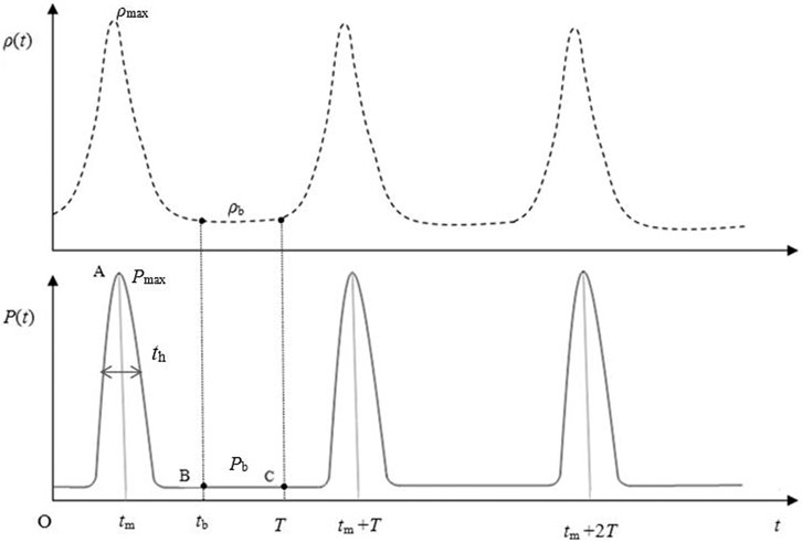
FPPRU1 consists of 139 hexagonal assemblies, including 138 UO2 fuel assemblies and one neutron source assembly located in the center of the core, as shown in Figure 2. The reflector of FPPRU1 contains the stationary reflector and the moving reflector. Inside the stationary reflector there are eight control rods for regulating the reactivity, including two regulating rods (IC-1 and IC-2 in Figure 2), two cubic compensating rods (RC-1 and RC-2 in Figure 2), two cylindrical compensating rods (RPR-1 and RPR-2 in Figure 2), and two safety rods (SEP-1 and SEP-2 in Figure 2). The moving reflector consists of one main moving reflector MMR and one auxiliary moving reflector AMR, which are both arranged opposite one side of the core, as shown in Figure 2. The material of both reflectors and control rods is stainless steel. The periodic reactivity is accomplished by the combination of the moving reflector MMR and auxiliary moving reflector AMR (MMR and AMR in Figure 2). The rotation speeds of MMR and AMR are 600 r/min and 300 r/min, respectively. For each period (T = 200 ms), when AMR and MMR arrive at the position in Figure 2, the two reflectors completely block the leakage path of neutrons outward, and the reactivity reaches the maximum. After AMR and MMR move away from the position in Figure 2, the reactivity gradually decreases and finally stabilizes to the minimum ρb, forming the change of reactivity and power shown in Figure 5.
As shown in Figure 5, under the stable operation of the fast periodic pulsed reactor, the reactivity ρ(t) and power P(t) vary periodically at a certain frequency. T is the period, and each period could be divided into two phases: pulse phase and background phase. For the first period from time 0∼T, OAB (from time 0∼tb) stands for the pulse phase and BC (from time tb∼T) stands for the background phase. th is the half-width of the pulse. ρmax is the maximum reactivity, and ρb is the background reactivity. Pmax is the maximum power, and Pb is the background power. There is little change in the reactivity within BC, and ρb could be approximated as a constant. In one period, the integral of power from 0∼T and from tb ∼T are the total energy Et and the background energy Eb, respectively. The integral of power from 0 ∼ tb is the pulse energy Ep, and Ep = Et- Eb.
FPPRU2 consists of 101 hexagonal assemblies, including 100 UO2 fuel assemblies and one neutron source assembly located in the center of the core. All the assemblies are arranged in a double-layer stainless steel barrel. The reflector of FPPRU contains the stationary reflector and the moving reflector. Inside the stationary reflector, there are eight control rods for regulating the reactivity, including two regulating rods (IC-1 and IC-2 in Figure 3), four compensating rods (RC-1, RC-2, RPR-1, and RPR-2 in Figure 3), and two safety rods (SEP-1 and SEP-2 in Figure 3). The moving reflector consists of one main moving reflector MMR and one auxiliary moving reflector AMR (MMR and AMR in Figure 3), which are both arranged opposite to one side of the core, as shown in Figure 3. FPPRU2 produces power pulses in the same way with FPPRU1. Different from FPPRU1, the materials of the reflectors and control rods of FPPRU2 are beryllium and B4C, respectively.
As shown in Figure 4, each fuel assembly consists of seven fuel elements and 0.5 mm thick outer stainless steel cladding. The outer radius of the fuel assembly is 3.464 cm. The distance between adjacent fuel elements in the assembly is 1.11 cm. Each fuel element is made up of UO2, He gas gap, and stainless steel cladding from inside to outside, and the outer radius are 0.45, 0.46, and 0.50 cm, respectively. The length of the UO2 active zone of the fuel element is 50 cm. Up and down the active zone are both the axial reflectors with 10 cm length. The materials of the axial reflectors of FPPRU1 and FPPRU2 are stainless steel and beryllium, respectively.
Calculation of Neutronic Parameters and Determination of Core Design Schemes
The neutronic parameters of FPPRU1 and FPPRU2, including the criticality, dynamic parameters, neutron energy spectrum, and power distribution, are calculated in the paper using the MCNP code. And based on the neutronic characteristics, the core design scheme is determined.
Criticality
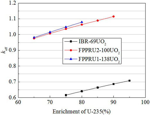
In the design of the FPPRU, considering the burn up during the reactor lifetime, the uncertainty of U-235 enrichment, and the impurity of the reactor reflector, the reserved reactivity ρr should not be less than about 45 mk (1mk = 0.001), ensuring the long-term operation for the reactor. Figure 6 shows the relationship between the maximum effective multiplication factor keff vs. the enrichment of U-235 for several core design schemes.
As shown in Figure 6, for FPPRU1, when U-235 enrichment is 75%, the reserved reactivity ρr (ρr = (keff−1)/keff) is 47.69 mk. For FPPRU2, when U-235 enrichment is 77%, the reserved reactivity ρr is 44.87 mk. These two core loading schemes basically meet the requirement of reserved reactivity and can reach a shutdown margin over −25 mk (−28.63 mk and −27.05 mk for FPPRU1 and FPPRU2, respectively).
The maximum effective multiplication factor keff of IBR-69UO2 is also given in Figure 6. IBR-69UO2 is the reactor that only replaces the PuO2 fuel of the IBR-2M reactor with the UO2 fuel. The keff of IBR-69UO2 clearly shows that more fuel assemblies must be used to reach criticality if UO2 is used as fuel.
Dynamic Parameters
The effective delayed neutron fraction βeff and neutron generation time Λ play very important roles in reactor dynamics. For the fast periodic pulsed reactor, these two dynamic parameters have great influence on the dynamics under periodic pulse operation. βeff and Λ are calculated for several reactors with different reflector materials using the MCNP code, as shown in Table 1.

TABLE 1. Calculating results of the effective delayed neutron fraction βeff and neutron generation time Λ.
The IBR-2M reactor uses PuO2 as fuel, and the reflector is made of stainless steel. The neutron generation time is 65 ns, and the half-width of the pulse is 245 µs (Pepelyshev and Popov, 2006a). In general, the smaller the neutron generation time, the narrower the half-width of the pulse. Since the design is intended to achieve a narrower half-width, it is hoped that the neutron generation time could be as small as possible. As could be seen from Table 1, if the material of the IBR-2M reflector is replaced with beryllium, the neutron generation time Λ will increase significantly to 327 ns. Compared with stainless steel, beryllium is a much better material for slowing down neutrons. More fast neutrons will be moderated to thermal neutrons in the reflector and would be reflected back to the core, which will both make the neutrons disappear much slower and increase the neutron generation time Λ significantly. For the same reason, the FPPRU2 reactor using beryllium as the reflector material requires fewer fuel assemblies to reach criticality than FPPRU1 using stainless steel as the reflector material. The neutron generation time Λ of FPPRU2 is as high as 1,477 ns, much higher than 114.9 ns of FPPRU2. Therefore, from the view of the half-width of the pulse, FPPRU1 with a stainless steel reflector would be better. It can also be seen from Table 1 that the effective delayed neutron fraction βeff of FPPRU1 and FPPRU2 with UO2 as fuel are similar, and are both much higher than that of IBR-2M with PuO2 as fuel. It is mainly due to that more delayed neutrons are released in the fission of U-235. In addition, the difference between energy spectrums of IBR-2 and FPPRU also has some influence.
Neutron Energy Spectrum
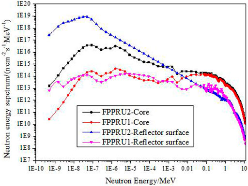
Figure 7 shows the neutron energy spectrum in the core and on the stationary reflector surface of FPPRU1 and FPPRU2 at average power 2 MW. Table 2 shows the neutron flux density and the average neutron energy in the core and on the stationary reflector surface. The neutrons are divided into four groups by energy, that is, the thermal group (0–0.414 eV), the epithermal group (0.414 eV–10 keV), the fast group one (0.01–0.1 MeV), and the fast group two (0.1–10 MeV). The mean neutron energy in the cores of FPPRU1 and FPPRU2 are 0.9243 and 0.9186 MeV, respectively. The average neutron energy on the stationary reflector surface of FPPRU1 and FPPRU2 are 0.5505 and 0.3596 MeV, respectively. The neutron energy spectrum on the surface of FPPRU2 reflector is softer than that on the surface of FPPRU1. It means that FPPRU2 is inferior to obtain a faster neutron beam. The main reason is that much more neutrons are moderated by beryllium in FPPRU2. As faster neutron beam is expected to be achieved in the design, from the view of the neutron energy spectrum, the FPPRU1 core scheme is preferred in this article. In addition, the fast neutron flux density (>0.01 MeV) in the core and on the stationary reflector surface of FPPRU1 are 8.88 × 10¹³ n/(cm2·s) and 8.10 × 10¹² n/(cm2·s), respectively.
Power Distribution
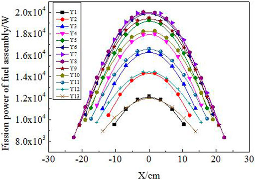
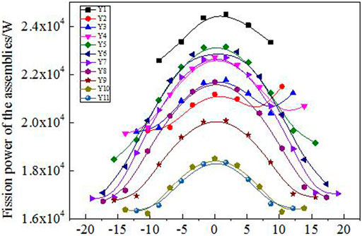
The fission power distribution of FPPRU1 and FPPRU2 fuel assemblies at average power 2 MW is shown in Figures 8, 9, respectively. From the bottom to the top of FPPRU1 core (Figure 2), Y1,Y2, …, Y13 in Figure 8 stand for the first layer, second layer, … thirteenth layer fuel assemblies, respectively. And from the bottom to the top of FPPRU2 core (Figure 3), Y1,Y2, …, Y11 in Figure 9 stand for the first layer, second layer, … eleventh layer fuel assemblies, respectively. X in Figures 8, 9 represents the coordinate of each fuel assembly in the direction of the X axis, and the coordinate of the center of the core on the X axis is 0.
From Figures 8, 9 it could be seen that the closer the fuel assembly to the center of FPPRU1 core, the greater the fission power basically. However, for FPPRU2, the fission power of Y1 layer fuel assemblies is the largest. As the safety rods of FRRPU2 (SEP-1 and SEP-2 in Figure 3) are at the top in the calculation, downside the Y1 layer fuel assemblies are all beryllium reflector. Beryllium moderates neutrons and reflects neutrons back to the core. The thermal neutrons are much more in the Y1 layer fuel assemblies, and thus, the fission power is higher than that of other layer fuel assemblies. It could also be seen from Figure 9 that the fission power of FPPRU2 Y1,Y2,Y3, and Y4 layers is not symmetric. The reason is that the size of the two compensating rods RPR-1 and RPR-2 in Figure 3 is not the same in the design.
The fission energy deposition and gamma energy deposition in the core components, including the auxiliary moving reflector, the control rod, and the fuel assembly, are shown in Table 3. According to Table 3, at average power 2 MW, the maximum energy deposition in the fuel assembly of FPPRU1 and FPPRU2 is 19.65 and 22.86 kW, respectively. The nonuniformity coefficient of FPPRU1 radial power is 1.383, which is larger than 1.225 of FPPRU2. The reason is that FPPRU2 reflector (beryllium) could moderate neutrons much better and the power of the outer fuel assemblies is relatively higher.
The energy deposition in the stationary beryllium reflector of FPPRU2 is 12 kW, which is 3.72 times as much as that in the stationary stainless steel reflector of FPPRU1. The material of FPPRU1 and FPPRU2 control rods is stainless steel and B4C, respectively. Among the eight control rods of FPPRU2, the compensating rod (RC-1 or RC-2 in Figure 3) has the largest energy deposition 2.48 kW. For FPPRU1, the compensating rod (RC-1 or RC-2 in Figure 2) also has the largest energy deposition, and the value is 0.71 kW. Therefore, under the condition of natural air cooling, the thermal safety of the stationary reflector of FPPRU1 is better.
Determination of Core Design Schemes
Compared with the FPPRU1 design scheme, the advantages of FPPRU2 design scheme are that less fuel assemblies are needed to reach criticality, and the nonuniformity coefficient of the radial power is smaller. However, the disadvantages of FPPRU2 are more obvious. The neutron generation time of FPPRU2 is too long to achieve ideal neutron pulse with narrow half-width. The neutron energy spectrum of FPPRU2 is softer, not beneficial for producing more fast neutrons. The energy deposition in the stationary reflector is much more, not conductive to heat dissipation. As the purpose of the design is to achieve narrower half-width pulse and harder neutron energy spectrum, the design scheme of FPPRU1 is selected. The cost is that more fuel assemblies are needed to reach criticality and the nonuniformity coefficient of the radial power is relatively high.
Reactor Dynamics
Reactor dynamics plays a very important role for the fast periodic pulsed reactor. So far, lots of research have been performed on the dynamics for the IBR-2 type reactor (Pepelyshev and Popov, 2006a; Pepelyshev and Popov, 2006b; Chan and Pepelyshev, 2008; Chan and Pepelyshev, 2010; Pepelyshev et al., 2015; Pepelyshev et al., 2017; Brezhnev et al., 2017). In this article, the critical search method for studying reactor dynamics is established based on the basic characteristics of the fast periodic pulsed reactor. Furthermore, the theoretical estimation formula which could show the difference between FPPRU1 dynamics and IBR-2 dynamics clearly and intuitively is also derived. And the pulse parameters of FPPRU1 and IBR-2 are compared using the critical search method and the theoretical estimation formula.
Critical Search Method
The critical search method is based on the point kinetic model:
In Eqs. 1, 2, αi = βeff,i/βeff. ρ(t) and P(t) are the reactivity and power in Figure 5, respectively. βeff and βeff,i are the total and the ith-group effective delayed neutron fraction, respectively. Λ is the neutron generation time and Ci(t) is the density of the ith-group delayed neutron precursor concentration.
From Eqs. 1, 2, P(t) would be obtained if ρ(t) is known. By changing the position of MMR and AMR gradually, the relative change of reactivity ρ(t) could be obtained by calculation or by experiment. Thus, the shape of reactivity ρ(t)is known. The shape function is defined as f(t), and then the relationship between ρ(t) and f(t) is as follows:
In Eq. 3, D is a constant. It is known that when the fast periodic pulsed reactor is under the stable operation, the peak power of every period is approximately equal, as shown in Figure 5. By gradually changing the value of D and solving Eqs. 1, 2 until every peak power is found to approach the same, D could be determined. In the calculation, if the peak power of the 200th period Pmax (200) and the peak power of the 500th period Pmax (500) could meet the condition |(Pmax (200)−Pmax (500))/Pmax (500)|<0.1%, then the D value is what we search for.
The dynamic characteristic of the fast periodic pulsed reactor is very special. It is that only one fixed D value exists if the basic parameters of the reactor, including f(t), βeff, Λ, are determined. And with D being one fixed value, the ratio of peak power to average power Pmax/Pt and the ratio of background energy to total energy Eb/Et are also unchangeable. Meanwhile, the absolute power Pmax and the absolute energy Eb could be adjusted by rising or dropping the control rods in the stationary reflector.
Theoretical Estimation Formula
Pulse parameters under stable operation, including relative power Pmax/Pt and relative energy Eb/Et, are critically important in measuring the dynamic performance of the fast periodic pulsed reactor. In order to study Pmax/Pt and Eb/Et in detail and to show the difference between IBR-2 and FPPRU1 dynamics intuitively, the theoretical estimation formulas are derived in the article.
From Eq. 2, the following could be obtained:
When the reactor is under stable periodic pulse operation, the production and the decay of delayed neutron precursors reach a balance; as a result, Ci(0)≈Ci(T) and
As shown in Figure 5, from time tb, the core reactivity stabilizes at ρb and the following is obtained:
Integrating Eq. 6 on both side from tb to T, the following is obtained:
From time tb, the power decreases at the decay rate of the delayed neutron precursors, as shown in Figure 5. As the change of power within time tb∼T is very little, the left-hand term of Eq. 7 is approximately 0. Then it could be achieved as follows:
From Eqs. 5, 7, Eb/Et takes the form as follows:
Assuming the integral pulse energy Ep is proportional to the product of peak power Pmax and half-width th, then the following can be obtained:
k in Eq. 10 is the proportional coefficient. For IBR-2 with PuO2 as fuel, according to the experimental data, k ≈ 1. For FPPRU1, according to the numerical results of the critical search method, k ≈ 1.5. Using Eqs. 9, 10, the following could be obtained:
Eqs. 9, 11 are the theoretical estimation formula describing Eb/Et and Pmax/Pt respectively. As can be seen intuitively from Eqs. 9, 11, Pmax/Pt increases with the rise of |ρb| and T, and with the drop of βeff and th. Eb/Et decreases with the rise of |ρb| and the drop of βeff. Thus, the theoretical estimation formula provides a simple way to analyze the factors affecting the pulse parameters clearly and intuitively, and establish a theoretical basis for improving the quality of the pulse parameters.
Comparison of Pulse Parameters of IBR-2 and FPPRU1
The qualities of pulse parameters of the fast periodic pulsed reactors with different fissile materials as fuel are quite different. In this article, the pulse parameters of IBR-2 with PuO2 as fuel are compared with those of FPPRU1 with UO2 as fuel. The results are shown in Table 4.
As shown in Table 4, both the critical search method and the theoretical estimation formula are used to calculate the pulse parameters. For IBR-2, the results obtained with the critical search method are in good agreement with the experimental data on the whole. Eb/Et calculated with the two methods is in good accordance, proving both the two methods are feasible. It should be noted that Pmax/Pt obtained with the theoretical estimation formula is on the assumption that k is known in the calculation (k = 1 for IBR-2 and k = 1.5 for FPPRU1).
It could be known from Table 4 that, the relative peak power Pmax/Pt of FPPRU1 is much lower and the relative background energy Eb/Et is much higher. Thus, the quality of pulse parameters of FPPRU1 is worse than that of IBR-2. From Eq. 9, it is known that if βeff is larger, then Eb/Et is larger and Pmax/Pt is smaller, which means the quality of pulse parameters is worse. The number of the delayed neutron produced by U-235 and Pu-239 per fission are 0.0068 and 0.00215 (Huang, 2007), respectively. And βeff of FPPRU1 and IBR-2 are 0.00728 and 0.00216, respectively. Thus, the pulse parameters of FPPRU1 are of relative poor quality compared to that of IBR-2.
From Eqs. 9, 11, we know that some measures could be taken to increase the quality of pulse parameters of FPPRU1. For example, the period T could be increased by reducing the rotating speed of moving reflectors. And the half-width th could be decreased by optimizing the reactor design. However, the measures may conflict with each other. For instance, reducing the rotation speed of the moving reflectors would also increase the half-width th at the same time.
Thermal Hydraulics Calculation
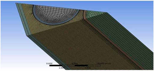
When FPPRU1 is under stable periodic operation at the average power 2MW, the peak power is about 370.92 MW. For the fuel assembly with the maximum power, the energy deposition in one pulse is about 4 kJ. The pulse frequency is 5 Hz and the half-width is 523.5 µs. The sub-channel model of the fuel assembly with the maximum power for analyzing the thermal hydraulic characteristics is established with FLUENT, as shown in Figure 10.
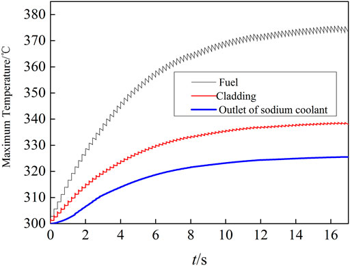
The model in Figure 10 is 1/12 of the whole fuel assembly shown in Figure 4. In the calculation, it is assumed that the inlet temperature of the sodium coolant is 300 °C and the flow rate of sodium coolant in one fuel assembly is 800 L/h. The changes of the maximum temperature of the fuel and the cladding and the maximum outlet temperature of sodium coolant are shown in Figure 11.
As seen from Figure 11, the temperature of the fuel and the coolant rise gradually and reach the balance after operating for about 17 s. The pulses only cause small jagged fluctuations to the temperature. The maximum fuel temperature and the coolant outlet temperature are 375 and 325 °C respectively, which means that the thermal safety under stable periodic operation could be guaranteed.
Discussion
The sodium cooling fast periodic pulsed reactor with UO2 as fuel (FPPRU) is designed, and the feasibility is studied in this article. Two typical core load schemes (FPPRU1 and FPPRU2) with stainless steel or beryllium as the reflector are compared. It is found that FPPRU1 with the stainless steel as the reflector has better performance such as narrower half-width of the pulse, harder neutron energy spectrum on the reflector surface, and less energy deposition in the stationary reflector. On the other hand, the downside of FPPRU1 is that more fuel assemblies have to be loaded to reach criticality. In order to study the reactor dynamics, the critical search method is established. Furthermore, the theoretical estimation formula which could clearly show the difference between the pulse parameters of FPPRU1 and IBR-2 is derived. The two methods are verified by the IBR-2 experimental data and are applied to the calculation of FPPRU1. The results show that the quality of the pulse parameters of FPPRU1 is not as good as that of IBR-2. In order to study the thermal safety under stable periodic operation, the sub-channel model of the FPPRU1 fuel assembly is built, and it is found that the maximum fuel temperature is not very high and thus is acceptable. On the whole, the sodium cooling fast periodic pulsed reactor with UO2 as fuel is feasible in neutronics and thermal hydraulics, but the quality of the pulse parameters needs to be improved further.
Data Availability Statement
The original contributions presented in the study are included in the article/Supplementary Material; further inquiries can be directed to the corresponding author.
Author Contributions
All authors listed have made a substantial, direct, and intellectual contribution to the work and approved it for publication.
Conflict of Interest
The authors declare that the research was conducted in the absence of any commercial or financial relationships that could be construed as a potential conflict of interest.
Publisher’s Note
All claims expressed in this article are solely those of the authors and do not necessarily represent those of their affiliated organizations, or those of the publisher, the editors and the reviewers. Any product that may be evaluated in this article, or claim that may be made by its manufacturer, is not guaranteed or endorsed by the publisher.
References
Ananiev, V. D., Lukasevich, I. B., Popov, V. E., and Romanova, N. V. (2020). IBR-2 Run Optimization Suggestions. At. Energ. 127 (3), 131–133. doi:10.1007/s10512-020-00598-3
Ananiev, V. D., Pepelyshev, Y. N., and Rogov, A. D. (2019). Optimization Study of the IBR-2 Reactor. Phys. Atom. Nuclei 82 (8), 1162–1174. doi:10.1134/S1063778819080039
Ata-Allah, S. S., Balagurov, A. M., Hashhash, A., Bobrikov, I. A., and Hamdy, S. (2016). Refinement of Atomic and Magnetic Structures Using Neutron Diffraction for Synthesized Bulk and Nano-Nickel Zinc Gallate Ferrite. Physica B: Condensed Matter 481 (481), 118–123. doi:10.1016/j.physb.2015.10.030
Avdeev, M. V., Rulev, A. A., Ushakova, E. E., Kosiachkin, Y. N., Petrenko, V. I., Gapon, I. V., et al. (2019). On Nanoscale Structure of Planar Electrochemical Interfaces Metal/liquid Lithium Ion Electrolyte by Neutron Reflectometry. Appl. Surf. Sci. 486, 287–291. doi:10.1016/j.physb.2015.10.03010.1016/j.apsusc.2019.04.241
Badawy, W. M., Duliu, O. G., Frontasyeva, M. V., El-Samman, H., and Mamikhin, S. V. (2020). Dataset of Elemental Compositions and Pollution Indices of Soil and Sediments: Nile River and delta -Egypt. Data in Brief 28 (105009), 105009–105010. doi:10.1016/j.dib.2019.105009
Bondarchenko, E. A., Pepyolyshev, Y. N., and Popov, A. K. (2001). Influence of Automatic Regulator Parameters on Power Transition Processes of the IBR-2 Reactor. Ann. Nucl. Energ. 28, 63–78. doi:10.1016/j.anucene.2006.04.002
Brezhnev, A. I., Gulevich, A. V., Kukharchuk, O. F., and Fokina, O. G. (2017). Assessment of the Critical Condition for the Operation of an IBR Reactor with a Subcritical Unit in an Equilibrium Mode. Nucl. Energ. Tech. 3 (2), 127–132. doi:10.1016/j.nucet.2017.05.007
Chan, L. Y., and Pepelyshev, Y. N. (2010). IBR-2 Dynamics with Power Shedding. At. Energ. 109 (2), 75–80. doi:10.1007/s10512-010-9326-8
Chan, L. Y., and Pepelyshev, Y. N. (2008). Model of IBR-2 Power Feedback Dynamics Taking Account of Slow Components. At Energy 104 (4), 262–267. doi:10.1007/s10512-008-9026-9
Dragunov, Y. G., Tretiyakov, I. T., Lopatkin, A. V., Romanova, N. V., Lukasevich, I. B., Ananyev, V. D., et al. (2012). Modernization of the IBR-2 Pulsed Research Reactor. At Energy 113 (1), 29–38. doi:10.1007/s10512-012-9591-9
Golovin, I. S., Mohamed, A. K., Bobrikov, I. A., and Balagurov, A. M. (2020). Time-Temperature-Transformation from Metastable to Equilibrium Structure in Fe-Ga. Mater. Lett. 263 (127257), 127257–127264. doi:10.1016/j.matlet.2019.127257
Kulikov, S. A., and Shabalin, E. P. (2013). Optimization of IBR-2M Moderator Parameters. At Energy 115 (1), 48–52. doi:10.1007/s10512-013-9747-2
Marina, F. (2011). Neutron Activation Analysis in the Life Sciences. Phys. Particles Nuclei 42 (2), 332–378. doi:10.1134/S1063779611020043
Pepelyshev, Y. N., and Popov, A. K. (2006). Influence of the Nearest Environment of the Core on the Power Pulse Dynamics in the IBR-2 Reactor. Ann. Nucl. Energ. 33, 813–819. doi:10.1016/j.anucene.2006.04.002
Pepelyshev, Y. N., and Popov, A. K. (2006). Investigation of Dynamical Reactivity Effects of IBR-2 Moving Reflectors. At Energy 101 (2), 549–554. doi:10.1007/s10512-006-0129-x
Pepelyshev, Y. N., Popov, A. K., and Sumkhuu, D. (2017). IBR-2M Reactor Power Feedback Parameters Evaluation Using Square Reactivity Oscillations. At Energy 122 (5), 75–80. doi:10.1007/s10512-017-0238-8
Pepelyshev, Y. N., Popov, A. K., and Sumkhuu, D. (2015). Model of the IBR-2M Pulsed Reactor Dynamics for Investigating Transition Processes in a Wide Range of Power Variation. Ann. Nucl. Energ. (85), 488–493. doi:10.1016/j.anucene.2015.06.002
Pepelyshev, Y. N., Vinogradov, A. V., and Rogov, A. D. (2010). “On Some Issues of Safety of Research Pulsed Reactor IBR-2,” in International Conference on Current Problems in Nuclear Physics and Atomic Energy, Kiev (Ukraine), June 7–12.
Turchenko, V., Kostishyn, V. G., Trukhanov, S., Damay, F., Porcher, F., Balasoiu, M., et al. (2020). Crystal and Magnetic Structures, Magnetic and Ferroelectric Properties of Strontium Ferrite Partially Substituted with in Ions. J. Alloys Compounds 821 (153412), 153412–153417. doi:10.1016/j.jallcom.2019.153412
Keywords: pulse parameters, periodic, pulsed reactor, UO2, feasibility
Citation: Zhang L, Jiang X, Zhang X, Ma T, Chen S, Wang L, Li D and Chen L (2021) Feasibility Study for the Fast Periodic Pulsed Reactor with UO2 Fuel. Front. Energy Res. 9:702952. doi: 10.3389/fenrg.2021.702952
Received: 30 April 2021; Accepted: 25 June 2021;
Published: 30 July 2021.
Edited by:
Qian Zhang, Harbin Engineering University, ChinaReviewed by:
Peiwei Sun, Xi'an Jiaotong University, ChinaQuan Gan, Hefei Institutes of Physical Science (CAS), China
Jinsen Xie, University of South China, China
Copyright © 2021 Zhang, Jiang, Zhang, Ma, Chen, Wang, Li and Chen. This is an open-access article distributed under the terms of the Creative Commons Attribution License (CC BY). The use, distribution or reproduction in other forums is permitted, provided the original author(s) and the copyright owner(s) are credited and that the original publication in this journal is cited, in accordance with accepted academic practice. No use, distribution or reproduction is permitted which does not comply with these terms.
*Correspondence: Xinbiao Jiang, emhhbmdsaWFuZzlAbmludC5hYy5jbg==
†These authors have contributed equally to this work and share first authorship
 Liang Zhang
 Xinbiao Jiang
 Xinyi Zhang1,2†