- 1CNPC Engineering Technology R&D Company Limited, Beijing, China
- 2China Petroleum Technology Development Company Limited, Middle East Branch, Beijing, China
- 3School of Petroleum Engineering in China University of Petroleum (East China), Qingdao, China
In the current numerical simulation studies, bottom water in Class II hydrate-bearing layers is represented by grids with high water saturation that significantly extends the calculation time if the volume of the bottom water is large or grid size is small. Moreover, the influence of the bottom water volume on the depressurization performance of Class II hydrate-bearing layers has not been fully investigated. In this study, the Fetkovich analytic aquifer model was coupled with a simulation model of a hydrate reservoir to accelerate the simulation of Class II hydrate-bearing layers. Then the simulation results and calculation time were compared between the coupled model and the model in which the bottom water layer is only represented by grids. Finally, the influence of the bottom water volume on the productivity of gas and water in the depressurization method was investigated and the variation of pressure, temperature, and hydrate saturation during the production process was analyzed. The results show that the coupled model can significantly reduce the simulation time of Class II hydrate-bearing layer while ensuring calculation accuracy. When the pore volume of the aquifer increases to 20 times that of the bottom water layer, the computation time of a single model in which the bottom water layer is represented by grids is 18.7 times that of the coupled model. Bottom water invasion slows down the depressurization, and therefore, the larger the aquifer, the lower the peak value of gas production, and the later it appears. However, the invading bottom water can provide heat for hydrate dissociation; therefore, the gas production rate of the hydrate-bearing layer with bottom water is higher than that of the hydrate-bearing layer without bottom water in the late development stage. Generally, the presence of bottom water reduces the cumulative gas production and increases the cumulative water production; therefore, the larger the aquifer, the more unfavorable the depressurization development of the hydrate-bearing layer.
Introduction
Natural gas hydrates (NGHs) are ice-like substances formed by gas and water that remain stable under low-temperature and high-pressure conditions (Chong et al., 2016; Aydin et al., 2016; Yang et al., 2019). They are mainly deposited in deep-water sediments and permafrost and have huge global reserves. NGHs have been regarded as one of the most important future alternative energy sources and pilot production tests have been conducted in several countries including the US, Canada, China, and Japan (Collett et al., 2011; Song et al., 2014; Li et al., 2018; Ye et al., 2020). The main method for developing hydrate-bearing layers (HBL) is to break the phase equilibrium condition of NGHs, which leads to the dissociation of NGHs into gas and water (Boswell et al., 2019; Ruan et al., 2021). According to these mechanisms, the main development methods can be divided into depressurization, thermal stimulation, inhibitor injection, and CO2 replacement, among which the depressurization method is currently the most economical method (Wei et al., 2018).
Moridis et al. investigated HBLs and divided them into three classes (Moridis et al., 2011a). Class I HBLs comprise an overlying hydrate layer and an underlying free gas layer. Class II HBLs contain a hydrate layer and a bottom water layer, whereas Class III HBLs only have a single hydrate layer (Moridis and Reagan, 2011). For Class II HBLs, the bottom water significantly affects the gas production because the invasion of bottom water from the underlying layer to the hydrate layer supplements the pressure drawdown caused by gas production, and therefore, the depressurization speed decreases (Liu et al., 2018a; Esmaeilzadeh et al., 2020; Pang et al., 2021). Over the past few years, many researchers have investigated the performance of Class II HBLs using the experimental and simulation methods. Based on the geological parameters of HBLs in Malik, Canada, Moridis et al. (2011a; 2011b) carried out numerical simulation studies and compared the performance of the depressurization method under different perforation schemes. The results show that the method involves a gas production interval within the water layer, and heating of the outer surface of the wellbore gives the best performance. Reagan et al. (2008) studied the influence of permeability, porosity, and heterogeneity on the development of class II HBLs using the Tough + Hydrate simulator. The results show that the gas production is dependent strongly on the formation porosity and less on the anisotropy: The smaller the well spacing, the greater the gas production over short-time periods. Liu et al. (2018b) coupled the particle swarm optimization algorithm and HydrateResSim (open-source edition of Tough + Hydrate) and key parameters such as the conversion time of depressurization to hot water injection, injected water temperature, and injection–production ratio were optimized. Uddin et al. (2014) investigated the performance of a Class II HBL in the Mallik area using a numerical simulation method and found that owing to the low pressure and temperature, the production from the middle hydrate layer yields better performance than that from the upper layer. Li et al. (2021) analyzed the performance of Class II HBLs using the CMG-STARS module. The simulation results show that if the bottom water layer is perforated, water production significantly increases, and the bottom water layer should not be perforated if permeability is greater than 1,000 mD. Bhade and Phirani (2015) investigated the influence of heterogeneity on the depressurization performance of Class II HBLs. The results show that the characterization of the aquifer is important for the depressurization performance of Class II HBLs. Along with an increase in the permeability of the aquifer, gas production decreases, and water production increases.
From the above discussion, it is clear that the mechanisms and depressurization performance of Class II HBLs have been comprehensively investigated. However, in these simulations, the aquifer is represented by grids that are saturated with water and the calculation time is significantly extended if the bottom water layer is thick or if the grid size is small. Moreover, the influence of aquifer volume on the depressurization performance has not been fully studied. Given this, the Fetkovich analytic aquifer model, which has been widely used in commercial software of the petroleum industry, is coupled with an HBL simulator. Then, the simulation results are validated, and the calculation time is compared between the coupled model and the model in which the bottom water layer is only represented by grids. Finally, a model was built based on the geological parameters of an HBL in the Shenhu area of the South China Sea, and the influence of bottom water volume on the depressurization performance of Class II HBLs was analyzed.
Coupling of Aquifer Model and Hydrate-Bearing Layers Model
Fetkovich Analytic Aquifer Model
The Fetkovich analytic aquifer model is based on the principle of material balance; that is, the volume of water at the initial time under the current pressure should be equal to the sum of the pore volume under the current pressure and the volume of water invading the adjacent reservoir (Fetkovich, 1971). When the source and sink are not considered in the aquifer, they can be expressed as
The rate of invasion water can be expressed as follows:
By combining Eq.2 and Eq.3, the following equation is obtained:
According to the above equations, the total water invasion rate in the time interval
Hydrate-Bearing Layers Numerical Simulation Model
At present, the commonly used numerical simulation tools for HBL development include the STOMP-HYD simulator of the Pacific Northwest National Laboratory in the United States, the MH21-HYDRES simulator of Japan, and the TOUGH + HYDRATE and HydrateResSim simulators of the Berkeley National Laboratory in the United States. (Li et al., 2016; Luo et al., 2020). Among these simulators, the phase equilibrium and kinetic models are the most widely used models (Moridis, 2003; Wan et al., 2020). The equilibrium model considers the hydrate formation and dissociation to occur at chemical equilibrium, and the system is always assumed to be equilibrium. For laboratory scale models, the timestep is quite small (seconds or minutes) and the assumption of equilibrium is hard to be satisfied. Therefore, the kinetic model should be selected under such circumstances. However, the timestep of field scale model is days or even months. The assumption of equilibrium is easily satisfied, and therefore, the equilibrium and kinetic model obtain quite similar results (Kowalsky and Moridis, 2007). The calculation process of the kinetic model is more complex, so the convergence is relatively poor, and the calculation time is longer. Therefore, a phase equilibrium model was used in this study considering that the field scale model is used. The components used only include methane and water, and the mass conservation equation for each component can be expressed as follows:
The energy conservation equation is as follows:
Hydrate formation and dissociation is based on the phase equilibrium condition. The phase equilibrium curve used in this study is the regression form proposed by Moridis et al. (2011b) as follows:
Coupling of the Fetkovich and Hydrate-Bearing Layers Models
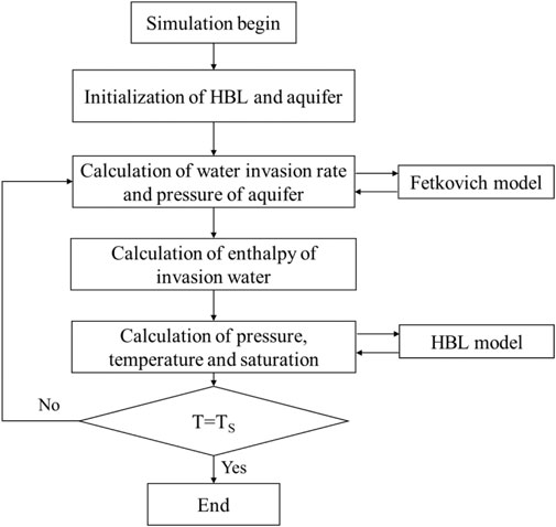
Figure 1 shows a diagram of the coupling process of the Fetkovich aquifer model and the HBL model. As shown in this figure, the widely used two-way coupling method was used to couple the two models. First, the HBL and aquifer models were initialized, and the temperature of the aquifer was set to be the same as the initial temperature of the adjacent HBL grid. When the simulation began, the pressure, temperature, and hydrate saturation of the HBL were obtained according to the numerical simulation model of the HBL. When the pressure of the grids adjacent to the aquifer is lower than the initial pressure of the aquifer, the total water invasion rate from the aquifer to the HBL in the next time step is calculated using Eq. 5, and the aquifer pressure is updated according to Eq. 2. According to the principles of the numerical simulation, the mass flow rate of water from the aquifer to the grids adjacent to the aquifer can be calculated according to the following equation:
The heat of the invading water was obtained according to the water temperature and the calculated invasion rate. Then, the mass flow rate and heat of the invasion water are considered the source and sink terms of mass and energy, respectively, in Eq. 6 and Eq. 7 to calculate the pressure, temperature, and fluid saturation of the HBL in the next step. The above steps are repeated until the predetermined simulation time TS is reached.
Validation and Computational Efficiency Analysis of the Coupled Model
No similar coupling model has been reported in the literature; therefore, no simulation results can be directly used to validate the coupled model proposed in this article. However, in the two-way coupling process, only related data are transferred, and the procedure used to compute outputs from the two models is not changed (Tran et al., 2005). Therefore, if the water invasion rate is computed correctly, the results can be considered reliable. Many commercial software packages of the petroleum industry have incorporated the Fetkovich model. In this study, the commercial software CMG-STARS module was used to validate the calculation results of the coupled model. To make the simulation results comparable, a single water phase that can be simulated by both the STARS module and the coupled model is used. The coupled model built is shown in Figure 2A and its basic parameters are listed in Table 1. As shown in Figure 2A, the model uses radial coordinates and is divided into 28 vertical grids, of which the top three grids represent the overburden with a total thickness of 10 m, and the remaining 25 grids represent a water layer with a total thickness of 25 m. According to the basic parameters in Table 1, the pore volume of the water layer is 9.42 × 10⁵ m3. The analytical aquifer is connected to the bottom of the water layer, and the outer boundaries are all no-flux boundaries except the bottom (water in the aquifer will flow from the aquifer to the water layer through the bottom). The initial pressures of the water layer and the analytical aquifer were both 13 MPa. A vertical well is located in the center and produces water at a fixed pressure of 4 MPa, which means that the inner boundary (wellbore boundary) is the Dirichlet boundary.
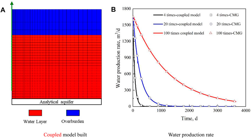
FIGURE 2. The coupled model built and results used for validation. (A) Coupled model built. (B) Water production rate.
Three cases were compared in which the pore volumes of the aquifer were 4, 20, and 100 times that of the bottom water layer. Figure 2B shows a comparison of the water production rates obtained by the STARS module and the coupled model. It can be seen that the initial water production rate is almost the same for the three cases, which indicates that the elastic energy of the water layer is sufficient at the beginning. However, with an increase in time, the difference in water production rates among the different cases gradually increases. An aquifer with a larger pore volume can provide more water flow from the aquifer to the adjacent layer, and therefore, the larger the pore volume of the aquifer, the slower the deceleration of the water production rate. From the comparison, it can be seen that the water production rates of the coupled model established in this study are consistent with those calculated by the STARS module, and the coupled model is reliable.
The advantage of the coupled model is that it uses an analytical aquifer model to characterize the bottom water layer, while the single HBL model can only increase the pore volume of the bottom water layer by increasing the number of grids. Therefore, the calculation time of the single model increased significantly when the aquifer was large. Figure 3 shows a comparison of the calculation results and calculation time of the coupling model and the single model. Because the case in which the pore volume of the aquifer is 100 times that of the bottom water layer requires too many grids for the single model and the simulation time is too long, only the other two cases are compared. As shown in Figure 3A, the water production rates simulated by the coupled and single models are almost the same, which indicates that the analytical aquifer model can accurately simulate the water invasion, and the calculation results of the coupled model are reliable. As shown in Figure 3B, when the pore volume of the aquifer is four times that of the bottom water layer, the calculation time of the coupled model is approximately 2 min (CPU: Intel Core i7 7,700; Memory: 8 GB), while the calculation time of the single model is approximately 7 min. When the pore volume of the aquifer increases to 20 times that of the bottom water layer, the calculation time of the coupled model is approximately 3 min, which is not a significant increase. However, the calculation time of the single model was increased to 56 min owing to the increase in the grid number. The computation time of the single model is 18.7 times that of the coupled model. The above results show that the coupled model can ensure calculation accuracy and significantly reduce the calculation time.
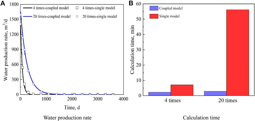
FIGURE 3. Simulation results and calculation time comparison of the coupled model and single model. (A) Water production rate. (B) Calculation time.
Case Study
Numerical Simulation Model
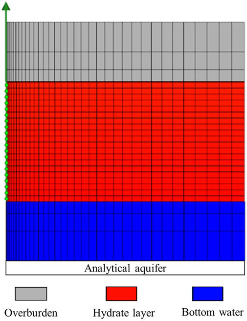
The numerical simulation model was demonstrated using the basic parameters of the HBL at station SH7 in the Shenhu area of the South China Sea, and the initial temperature and pressure of the model were 14.15°C and 13 MPa, respectively (Liu et al., 2012; Li et al., 2011). According to Eq. 8, the equilibrium pressure corresponding to 14.15°C is 11.53 MPa, and therefore, the hydrate is stable under the initial conditions. The model can be divided into overburden, hydrate, and bottom water layers as shown in Figure 4. The thickness of the overburden layer is 10 m and that of the hydrate layer is 20 m. It is recommended that aquifers be modeled at least partially using water-filled grid blocks because if flow reversal occurs, the model with no water-filled grid blocks will encounter convergence problems [CMG (Computer Modelling Group), 2020]. The aquifer used in this study is composed of two parts. One part is the bottom water layer with 10 m thickness and the other part is an analytical aquifer represented by the Fetkovich model. A vertical well was located at the center of the formation. Similar to the model built in Validation and Computational Efficiency Analysis of the Coupled Model Section, the outer boundaries are all no-flux boundaries except the bottom, and the inner boundary is the Dirichlet boundary. The vertical well maintained a constant bottomhole pressure of 4 MPa during the entire depressurization process, and the perforated section of the vertical well ran through the entire hydrate layer. In the model, the hydrate phase cannot flow, and its relative permeability is 0. The modified STONE model is used for the gas-water relative permeability, which is expressed as follows (Moridis, 2003; Liu et al., 2020):
The widely used van Genuchten function is used for the capillary pressure, and it can be expressed as follows (Hou et al., 2016):
The specific parameters of the model are listed in Table 2. Three cases were simulated with the analytical aquifer model, and the total pore volumes of the aquifer (the sum of the pore volumes of the water layer and the aquifer model) were 4 (case 2), 20 (case 3), and 100 (case 4) times that of the hydrate layer. A class III HBL model (case 1) which only has overburden, underburden, and hydrate layers was also simulated for comparison. This case does not have a water layer or an analytic aquifer model; therefore, the pore volumes of the water layer and aquifer model are 0. The simulation time for all the four cases was 10 years.
Influence of Aquifer on Gas and Water Production
The gas production rate and cumulative gas production for each case are shown in Figure 5. It can be seen that the pore volume of the aquifer has a significant impact on the depressurization performance. The peak daily gas production rates for cases 1 to 4 are 4.24 × 10⁴, 3.33 × 10⁴, 2.61 × 10⁴, and 1.20 × 10⁴ m3/d, respectively, and the peak gas production times are 250, 310, 550, and 1,270 days, respectively, indicating that the higher the pore volume of the aquifer, the lower the gas production peak, and the later the gas production peak appears. This is mainly because when the aquifer is large, the amount of water that can flow into the HBL from the aquifer is also large, and the depressurization rate of the HBL is accordingly low. The hydrate dissociation rate is positively correlated with the amplitude of depressurization; therefore, the larger the aquifer, the lower the dissociation and gas production rates. In the later stage of depressurization development, the gas production rate shows the opposite trend; that is, the larger the aquifer, the higher the gas production rate. This is mainly because hydrate dissociation is an endothermic reaction. When there is no aquifer, hydrate dissociation in the early stage of depressurization causes the reservoir temperature to rapidly decrease and move closer to the phase equilibrium temperature of the hydrate; thus, the dissociation rate decreases significantly, and the gas production decreases accordingly. When the bottom water layer exists, the heat energy contained in the invasion water can promote hydrate dissociation, and therefore, the gas production for case 4 with the largest aquifer is also the highest in the later stages of depressurization. However, it can be seen from Figure 5B that case 1 without an aquifer can achieve the highest cumulative gas production in 10 years of depressurization development, followed by cases 2, 3, and 4 in order, where the largest aquifer achieves the lowest cumulative gas production.
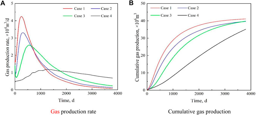
FIGURE 5. Influence of aquifer on gas production. (A) Gas production rate. (B) Cumulative gas production.
A comparison of the water production rate and cumulative water production for each case is shown in Figure 6. It can be seen that in the early stage of depressurization, the water production rates for all the four cases were high. However, when there is no bottom water (case 1), the water production rate decreases rapidly with a decrease in the dissociation rate of the hydrate, while in the cases with bottom water, the decrease in the water production rate is slower. In the late stage of depressurization, the water production rates for cases 2 and 3 are close to those for case 1 owing to the limited pore volume of the aquifer. However, because of the large pore volume of the aquifer and sufficient water supply, the water production rate for case 4 is still significantly higher than those for the other cases after 10 years of depressurization development.
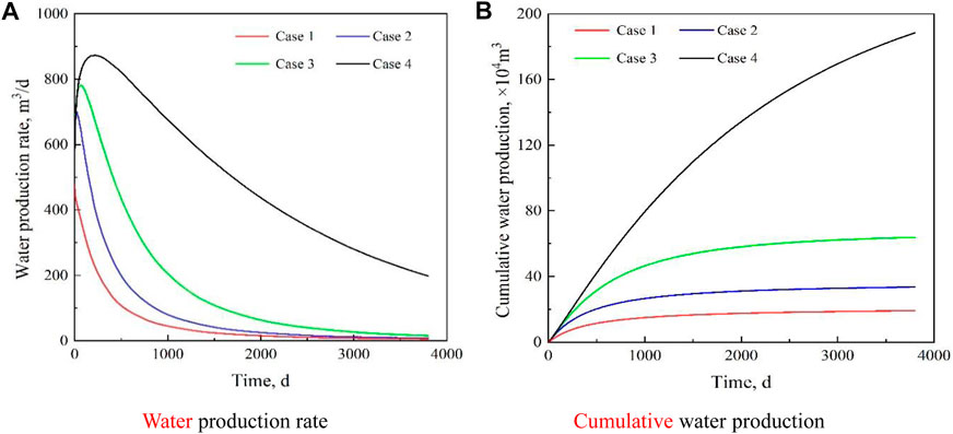
FIGURE 6. Influence of aquifer on water production. (A) Water production rate. (B) Cumulative water production.
Influence of the Aquifer on the Pressure of the Hydrate-Bearing Layers
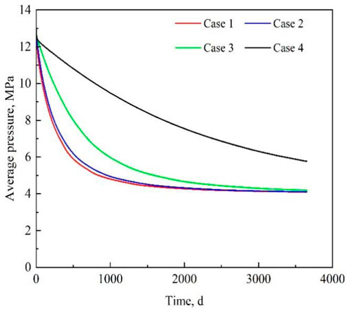
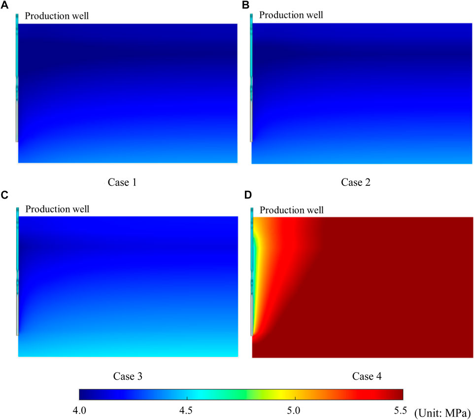
Figure 7 shows changes in the average pressure, and Figure 8 shows the pressure distribution of each case after 10 years of depressurization. It can be observed that the average pressure in all cases decreases with time. However, the larger the aquifer volume, the slower the pressure drop. After years of depressurization, the pressure of the entire HBL dropped to approximately 4MPa when there was no bottom water, as shown in Figure 8A. The pressure distributions for case 2 (Figure 8B) and case 3 (Figure 8C) are similar to those for case 1 owing to the smaller pore volume of the aquifer. However, when the pore volume of the aquifer was large (Figure 8D), only the reservoir pressure near the well was close to the bottom hole pressure, while the reservoir pressure far away from the well was still high, which indicates that the HBL can achieve effective depressurization when the aquifer is small, but it is difficult to achieve rapid depressurization when the bottom water is sufficient.
Influence of the Aquifer on the Temperature of the Hydrate-Bearing Layers
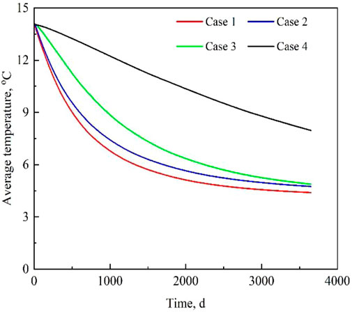
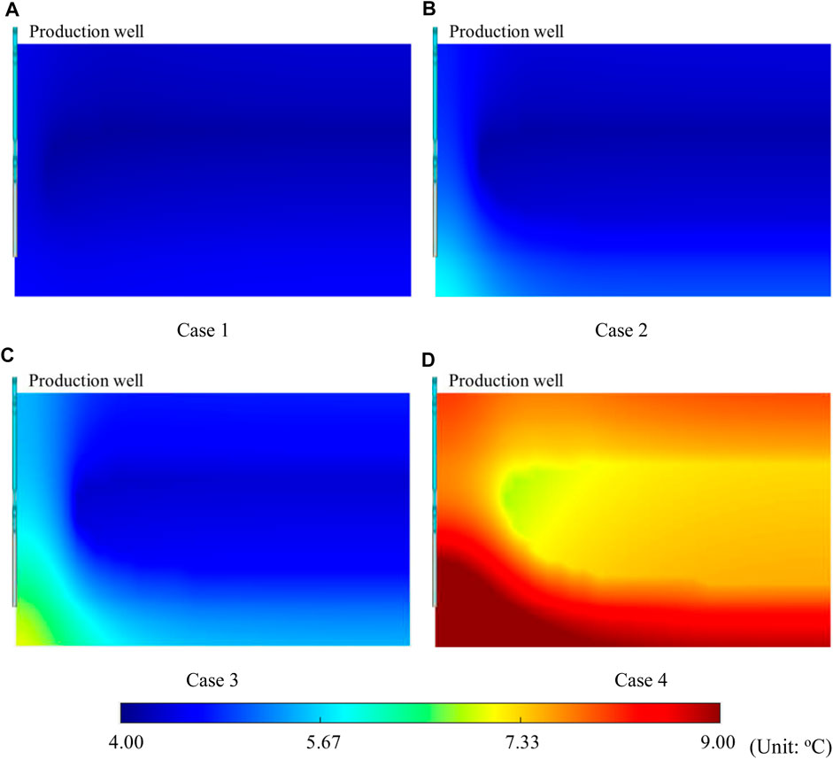
Figure 9 shows the changes in average temperature, and Figure 10 shows the temperature distribution for each case after 10 years of depressurization. It can be seen that the temperatures for all the cases decreased owing to the dissociation of the hydrate. The temperature of the whole HBL dropped to approximately 4.2°C, which corresponds to the phase equilibrium temperature of the bottom hole pressure of 4 MPa at the end of depressurization development because there is no external energy supplement for case 1 (Figure 10A). For cases 2 and 3 (Figures 10B,C), the temperature of the area far away from the vertical well also dropped to near the phase equilibrium temperature, but there was an evident cone-shaped high-temperature area at the bottom of the well. This is mainly because bottom water coning on the vertical well can supplement the heat energy consumed by hydrate dissociation near the bottom of the well. For case 4, the temperature of the HBL was significantly higher than the phase equilibrium temperature. This is mainly because it is difficult for the HBL to achieve rapid depressurization when the aquifer is large (Figure 10D); thus, the hydrate dissociation rate is lowered, and the thermal energy of the HBL is not fully utilized. Similar to cases 2 and 3, the temperature of the bottom water coning area in Figure 10D is also significantly higher than that of the non-coning area because of the energy supplement of the bottom water.
Influence of the Aquifer on the Hydrate Saturation of the Hydrate Bearing Layers
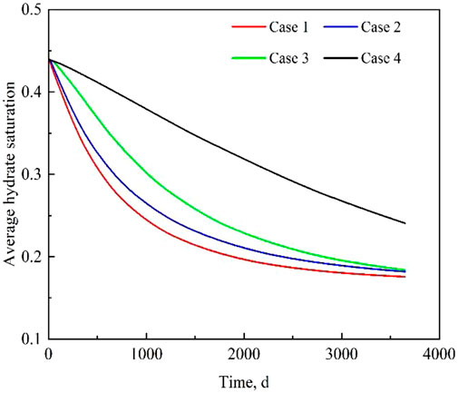
Figure 11 shows the changes in average hydrate saturation of the hydrate layer and Figure 12 shows the hydrate saturation distribution for each case after 10 years of depressurization. When depressurization begins, the hydrate near the well quickly dissociates because the near-well zone has the lowest pressure and the average hydrate saturation decreases. At the end of the depressurization development, the hydrate in the near-well zone was completely dissociated in all cases. However, the shapes of the hydrate dissociation region of the four cases were different. For case 1, the distribution of the hydrate saturation is approximately symmetrical in the vertical direction, while for other cases with bottom water, there is a cone-shaped dissociation zone near the bottom water; in addition, the larger the pore volume of the aquifer, the larger the area of the cone-shaped dissociation zone. This is mainly because the heat carried by the bottom water can effectively promote hydrate dissociation in the water invasion area. At the end of depressurization, there is still a large quantity of un-dissociated hydrate in each case, and the larger the aquifer, the greater the saturation of the remaining hydrate.
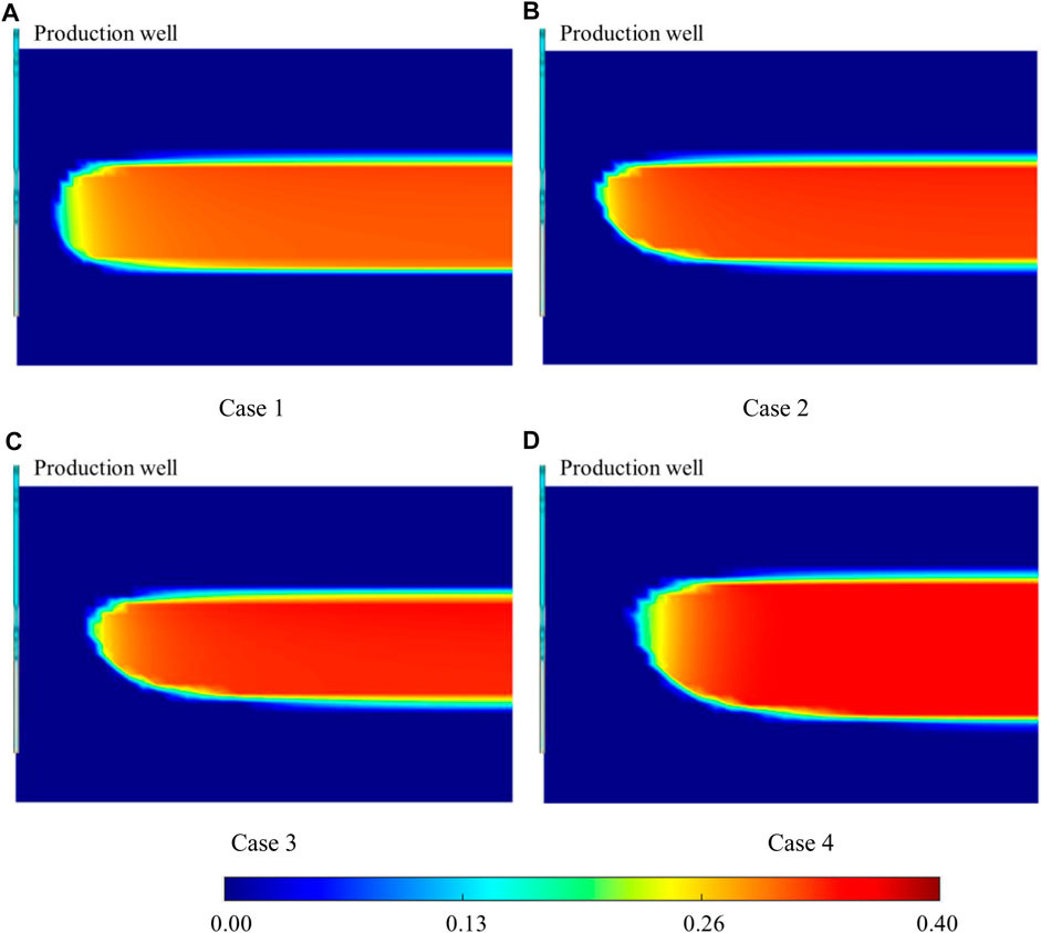
FIGURE 12. Hydrate saturation distribution of each case. (A) Case 1. (B) Case 2. (C) Case 3. (D) Case 4.
From the above analysis, it can be seen that bottom water can have a significant impact on the performance of the HBL. The larger the aquifer, the slower the depressurization rate, and the lower the corresponding gas production. Therefore, the invasion of bottom water is not conducive to the depressurization development of Class II HBLs.
Discussion
Although the coupled model built in this study shows good performance and the calculated water invasion rates are consistent with those obtained by the commercial software CMG, the reliability of the simulation results should be validated by physical experiments. However, at present, it is quite difficult to construct a physical model in which the upper layer is a hydrate layer and the lower layer is a water layer. Moreover, if the aquifer volume is large, the large size of the model will cause considerable difficulties in the implementation of the experiment. Therefore, new experimental setups and procedures should be investigated in the future.
Furthermore, field tests and studies have shown that many HBLs are poorly cemented, and therefore, sediment deformation should be evaluated, and the influence of sediment deformation on depressurization should be considered for this type of HBLs (Wan et al., 2018). This study emphasizes the coupling of the HBL and aquifer models to reduce the simulation time of Class II HBLs, and sediment deformation is neglected. An integrated model that includes the HBL, geomechanical, and analytical aquifer models should be developed in the future to investigate the performance of Class II HBLs.
Conclusion
A coupled numerical simulation model of the analytical aquifer model and the HBL model was proposed and validated. Using the model, the influence of bottom water on the gas depressurization performance was analyzed. The main conclusions are as follows:
1) By coupling the HBL and analytic aquifer numerical simulation models, the simulation time of a Class II hydrate reservoir with a large aquifer volume can be significantly reduced while ensuring calculation accuracy. For the bottom water layer investigated in this study, for which the pore volume of the aquifer is 20 times that of the bottom water layer, the computation time of the single model is 18.7 times that of the coupled model.
2) The larger the aquifer, the lower the peak value of gas production, and the later the peak value appears. When the pore volume of the aquifer is large, the water production remains high in the later stages of depressurization. The invasion of bottom water slows down the depressurization of the HBL, and the hydrate dissociation and gas production rates decrease. Furthermore, the larger the aquifer, the higher the pressure, temperature, and residual hydrate saturation at the end of depressurization.
3) Owing to high levels of hydrate dissociation, the temperature of the HBL decreases rapidly to the equilibrium temperature when there is no bottom water layer. When a bottom water layer is present, the invasion of the bottom water provides heat to the water invasion area, creating a cone-shaped hydrate dissociation area near the well.
Data Availability Statement
The original contributions presented in the study are included in the article/Supplementary Material, further inquiries can be directed to the corresponding author.
Author Contributions
JY: Writing—original draft, Methodology, Investigation. LZ: Supervision, Validation. YC: Supervision, Methodology, Data curation. WS: Visualization, review and editing. YL: Writing, simulation.
Funding
This work was financially supported by Basic Research and Strategic Reserve Technology Research Fund of CNPC (Grant No. 2017B4906) and Research Project of CNPC Engineering Technology R&D Company Limited (Grant No. CPETQ202111).
Conflict of Interest
JY, LZ, and WS were employed by the company CNPC Engineering Technology R&D Company Limited, and YC was employed by the company China Petroleum Technology Development Company Limited.
The remaining author declares that the research was conducted in the absence of any commercial or financial relationships that could be construed as a potential conflict of interest.
Publisher’s Note
All claims expressed in this article are solely those of the authors and do not necessarily represent those of their affiliated organizations, or those of the publisher, the editors and the reviewers. Any product that may be evaluated in this article, or claim that may be made by its manufacturer, is not guaranteed or endorsed by the publisher.
References
Aydin, G., Jang, H., and Topal, E. (2016). Energy Consumption Modeling Using Artificial Neural Networks: The Case of the World's Highest Consumers. Energ. Sourc. B: Econ. Plann. Pol. 11, 212–219. doi:10.1080/15567249.2015.1075086
Bhade, P., and Phirani, J. (2015). Effect of Geological Layers on Hydrate Dissociation in Natural Gas Hydrate Reservoirs. J. Nat. Gas Sci. Eng. 26, 1549–1560. doi:10.1016/j.jngse.2015.05.016
Boswell, R., Yoneda, J., and Waite, W. F. (2019). India National Gas Hydrate Program Expedition 02 Summary of Scientific Results: Evaluation of Natural Gas-Hydrate-Bearing Pressure Cores. Mar. Pet. Geology. 108, 143–153. doi:10.1016/j.marpetgeo.2018.10.020
Chong, Z. R., Yang, S. H. B., Babu, P., Linga, P., and Li, X.-S. (2016). Review of Natural Gas Hydrates as an Energy Resource: Prospects and Challenges. Appl. Energ. 162, 1633–1652. doi:10.1016/j.apenergy.2014.12.061
Collett, T. S., Lee, M. W., Agena, W. F., Miller, J. J., Lewis, K. A., Zyrianova, M. V., et al. (2011). Permafrost-associated Natural Gas Hydrate Occurrences on the Alaska North Slope. Mar. Pet. Geology. 28, 279–294. doi:10.1016/j.marpetgeo.2009.12.001
Esmaeilzadeh, F., Hamedi, N., Karimipourfard, D., and Rasoolzadeh, A. (2020). An Insight into the Role of the Association Equations of States in Gas Hydrate Modeling: a Review. Pet. Sci. 17, 1432–1450. doi:10.1007/s12182-020-00471-9
Fetkovich, M. J. (1971). A Simplified Approach to Water Influx Calculations-Finite Aquifer Systems. J. Pet. Technol. 23 (07), 814–828. doi:10.2118/2603-pa
Hou, J., Xia, Z., Li, S., Zhou, K., and Lu, N. (2016). Operation Parameter Optimization of a Gas Hydrate Reservoir Developed by Cyclic Hot Water Stimulation with a Separated-Zone Horizontal Well Based on Particle Swarm Algorithm. Energy 96, 581–591. doi:10.1016/j.energy.2015.12.066
Kowalsky, M. B., and Moridis, G. J. (2007). Comparison of Kinetic and Equilibrium Reaction Models in Simulating Gas Hydrate Behavior in Porous media. Energ. Convers. Manag. 48, 1850–1863. doi:10.1016/j.enconman.2007.01.017
Li, G., Moridis, G. J., Zhang, K., and Li, X.-s. (2011). The Use of Huff and Puff Method in a Single Horizontal Well in Gas Production from marine Gas Hydrate Deposits in the Shenhu Area of South China Sea. J. Pet. Sci. Eng. 77, 49–68. doi:10.1016/j.petrol.2011.02.009
Li, J.-f., Ye, J., Ye, J.-l., Qin, X.-w., Qiu, H.-j., Wu, N.-y., et al. (2018). The First Offshore Natural Gas Hydrate Production Test in South China Sea. China Geol. 1 (1), 5–16. doi:10.31035/cg2018003
Li, S., Li, S., Zheng, R., Li, Q., and Pang, W. (2021). Strategies for Gas Production from Class 2 Hydrate Accumulations by Depressurization. Fuel 286, 119380. doi:10.1016/j.fuel.2020.119380
Li, X.-S., Xu, C.-G., Zhang, Y., Ruan, X.-K., Li, G., and Wang, Y. (2016). Investigation into Gas Production from Natural Gas Hydrate: A Review. Appl. Energ. 172, 286–322. doi:10.1016/j.apenergy.2016.03.101
Liu, C., Ye, Y., Meng, Q., He, X., Lu, H., Zhang, J., et al. (2012). The Characteristics of Gas Hydrates Recovered from Shenhu Area in the South China Sea. Mar. Geology. 307-310, 22–27. doi:10.1016/j.margeo.2012.03.004
Liu, Y., Bai, Y., Xia, Z., and Hou, J. (2018a). Parameter Optimization of Depressurization−to−Hot−Water−Flooding in Heterogeneous Hydrate Bearing Layers Based on the Particle Swarm Optimization Algorithm. J. Nat. Gas Sci. Eng. 53, 403–415. doi:10.1016/j.jngse.2018.03.017
Liu, Y., Hou, J., Chen, Z., Su, H., Zhao, E., and Li, G. (2020). A Novel Natural Gas Hydrate Recovery Approach by Delivering Geothermal Energy through Dumpflooding. Energ. Convers. Manag. 209, 112623. doi:10.1016/j.enconman.2020.112623
Liu, Y., Hou, J., Zhao, H., Liu, X., and Xia, Z. (2018b). A Method to Recover Natural Gas Hydrates with Geothermal Energy Conveyed by CO2. Energy 144, 265–278. doi:10.1016/j.energy.2017.12.030
Luo, T., Li, Y., Madhusudhan, B. N., Sun, X., and Song, Y. (2020). Deformation Behaviors of Hydrate-Bearing Silty Sediment Induced by Depressurization and thermal Recovery. Appl. Energ. 276, 115468. doi:10.1016/j.apenergy.2020.115468
Moridis, G. J. J., Collett, T. S. S., Pooladi-Darvish, M., Hancock, S., Santamarina, C., Boswell, R., et al. (2011a). Challenges, Uncertainties, and Issues Facing Gas Production from Gas-Hydrate Deposits. SPE Reservoir Eval. Eng. 14, 76–112. doi:10.2118/131792-pa
Moridis, G. J. (2003). Numerical Studies of Gas Production from Methane Hydrates. SPE J. 8, 359–370. doi:10.2118/87330-pa
Moridis, G. J., and Reagan, M. T. (2011). Estimating the Upper Limit of Gas Production from Class 2 Hydrate Accumulations in the Permafrost: 1. Concepts, System Description, and the Production Base Case. J. Pet. Sci. Eng. 76, 194–204. doi:10.1016/j.petrol.2010.11.023
Moridis, G. J., Silpngarmlert, S., Reagan, M. T., Collett, T., and Zhang, K. (2011b). Gas Production from a Cold, Stratigraphically-Bounded Gas Hydrate deposit at the Mount Elbert Gas Hydrate Stratigraphic Test Well, Alaska North Slope: Implications of Uncertainties. Mar. Pet. Geology. 28, 517–534. doi:10.1016/j.marpetgeo.2010.01.005
Pang, X., Chen, Z., Jia, C., Wang, E., Shi, H., Wu, Z. Y., et al. (2021). Evaluation and Re-understanding of the Global Natural Gas Hydrate Resources. Pet. Sci. 18, 1–16. doi:10.1007/s12182-021-00568-9
Reagan, M., Moridis, G., and Zhang, K. (2008). “Sensitivity Analysis of Gas Production from Class 2 and Class 3 Hydrate Deposits,” in Offshore Technology Conference, May 5-8, 2008, Texas, USA. doi:10.4043/19554-ms
Ruan, X., Li, X.-S., and Xu, C.-G. (2021). A Review of Numerical Research on Gas Production from Natural Gas Hydrates in China. J. Nat. Gas Sci. Eng. 85, 103713. doi:10.1016/j.jngse.2020.103713
Song, Y., Yang, L., Zhao, J., Liu, W., Yang, M., Li, Y., et al. (2014). The Status of Natural Gas Hydrate Research in China: A Review. Renew. Sust. Energ. Rev. 31, 778–791. doi:10.1016/j.rser.2013.12.025
Tran, D., Nghiem, L., and Buchanan, B. (2005). “An Overview of Iterative Coupling between Geomechanical Deformation and Reservoir Flow,” in SPE International Thermal Operations and Heavy Oil Symposium, November 1-3, 2005, Alberta, Canada. doi:10.2118/97879-ms
Uddin, M., Wright, F., Dallimore, S., and Coombe, D. (2014). Gas Hydrate Dissociations in Mallik Hydrate Bearing Zones A, B, and C by Depressurization: Effect of Salinity and Hydration Number in Hydrate Dissociation. J. Nat. Gas Sci. Eng. 21, 40–63. doi:10.1016/j.jngse.2014.07.027
Wan, Q.-C., Si, H., Li, G., Feng, J.-C., and Li, B. (2020). Heterogeneity Properties of Methane Hydrate Formation in a Pilot-Scale Hydrate Simulator. Appl. Energ. 261, 114325. doi:10.1016/j.apenergy.2019.114325
Wan, Y., Wu, N., Hu, G., Xin, X., Jin, G., Liu, C., et al. (2018). Reservoir Stability in the Process of Natural Gas Hydrate Production by Depressurization in the Shenhu Area of the south China Sea. Nat. Gas Industry B 5, 631–643. doi:10.1016/j.ngib.2018.11.012
Wei, J., Fang, Y., Lu, H., Lu, H., Lu, J., Liang, J., et al. (2018). Distribution and Characteristics of Natural Gas Hydrates in the Shenhu Sea Area, South China Sea. Mar. Pet. Geology. 98, 622–628. doi:10.1016/j.marpetgeo.2018.07.028
Yang, M., Zhao, J., Zheng, J.-n., and Song, Y. (2019). Hydrate Reformation Characteristics in Natural Gas Hydrate Dissociation Process: A Review. Appl. Energ. 256, 113878. doi:10.1016/j.apenergy.2019.113878
Ye, J., Qin, X., Xie, W., Lu, H., Ma, B., Qiu, H., et al. (2020). The Second Natural Gas Hydrate Production Test in the South China Sea. China Geol. 3, 197–209. doi:10.31035/cg2020043
Glossary
Bg gas volume factor
Bw water volume factor
Bwi water volume factor at the initial pressure of the bottom water layer
cf rock compressibility (Pa-1)
Cr rock-specific heat capacity (J/kg/K)
Jw water productivity index (m3/Pa/s)
H grid thickness (m)
Hβ phase β enthalpy (J/kg)
Hd formation or dissociation enthalpy of HBL (J/m3)
k absolute permeability (m2)
Kr rock thermal conductivity (W/m2/C)
krg gas relative permeability
krw water relative permeability
Kβ phase β thermal conductivity (W/m2/C)
nG gas relative permeability index
nw water relative permeability index
Pcap capillary pressure (Pa)
Pco parameter in capillary pressure model (Pa)
Pe corresponding equilibrium pressure of temperature T (MPa)
pi initial pressure of the bottom water layer (Pa)
pwf aquifer internal boundary pressure (Pa)
qh heat source and sink terms (J/m3/s)
qw water invasion rate (m3/s)
qwj water mass flow rate from the aquifer to the adjacent grid j (kg/m3/s)
(qwi)max initial time maximum water invasion rate (m3/s)
re radius of outer boundary (m)
rw radius of wellbore (m)
S skin factor
SG gas saturation
SirG irreducible gas saturation
SirW irreducible water saturation
SW water saturation
Sβ phase β saturation
t time (s)
T temperature (K)
VB grid volume (m3)
W initial volume of bottom water in surface conditions (m3)
We volume of invasion water in reservoir condition (m3)
Wei total volume of invasion water when aquifer pressure decreases to zero (m3)
Greek symbols: ϕ porosity
κ component of the HBL model
ρr rock density (kg/m3)
ρβ phase β density (kg/m3)
ρw water density (kg/m3)
ε blackness
σ Stefan-Boltzmann constant (W/m2/K4)
Keywords: natural gas hydrate, depressurization, bottom aquifer, numerical simulation, analytic aquifer model
Citation: Yu J, Zhuo L, Chen Y, Sun W and Liu Y (2021) Production Performance Analysis of Class II Hydrate-Bearing Layers Based on an Analytic Aquifer Model. Front. Energy Res. 9:702456. doi: 10.3389/fenrg.2021.702456
Received: 29 April 2021; Accepted: 01 July 2021;
Published: 04 August 2021.
Edited by:
Chungang Xu, Guangzhou Institute of Energy Conversion (CAS), ChinaReviewed by:
Yi Wang, Guangzhou Institute of Energy Conversion (CAS), ChinaBai Jing, Zhengzhou University, China
Yanghui Li, Dalian University of Technology, China
Liu Jianwu, Guangzhou Institute of Energy Conversion (CAS), China
Copyright © 2021 Yu, Zhuo, Chen, Sun and Liu. This is an open-access article distributed under the terms of the Creative Commons Attribution License (CC BY). The use, distribution or reproduction in other forums is permitted, provided the original author(s) and the copyright owner(s) are credited and that the original publication in this journal is cited, in accordance with accepted academic practice. No use, distribution or reproduction is permitted which does not comply with these terms.
*Correspondence: Jing Yu, eXVqaW5nZHJpQDEyNi5jb20=
 Jing Yu1*
 Wenchao Sun
 Yongge Liu