 Yunlong Wang
 Nuo Chen
- China Southern Power Grid EHV Transmission Company, Kunming, China
There is a large number of grounding switches along the isolated ground wire for the de-icing in the large-scale wind farm. If any of these grounding switches are left open by accident, this can create an unexpected abnormal grounding point in the isolated ground wire. Based on the analysis of the output power of de-icing devices, the output power of different poles can be applied for the abnormal grounding point fault location. Since the rise of output current to the rated current of de-icing devices requires a long time to build up, the protective relay may lock the de-icing device before the output current reaches the rated current. Thus, the ratio of output energy of two poles can be selected to locate the abnormal grounding point. This study verified this location method by conducting a large number of simulations.
Introduction
The wind farms of the northeast area of Yunnan province are a significantly important renewable energy base in China’s Southern Power Grid (Miao et al., 2013). However, the cold rain in winter on the Yunnan-Guizhou Plateau freezes the ground wire of the transmission lines of the wind farms in this area (Juanjuan et al., 2012). To reduce the unfavorable harm induced by the freeze, a de-icing device that melts the ice in the ground wires, by injecting the direct current (DC) to ground wires to heat them (Sun et al., 2011; Zhu et al., 2019a), is widely applied in the China Southern Power Grid. Although the DC de-icing device can eliminate the ice in ground wires, studies on the fault location for ground wires are urgently needed. In addition, the ground wire, which connects the earth with the tower, needs to be isolated from the tower for the propagation of the DC current. Thus, any grounding points in the tower can block the de-icing for the whole line (Hao et al., 2015; Jiazheng et al., 2016; Zhu et al., 2019a; Zhu et al., 2019b; Guo et al., 2019; Haleem and Rajapakse, 2019; De Oliveira Neto et al., 2021). To maintain the lightning protection of ground wires, grounding switches are distributed along transmission lines. Normally, grounding switches are closed to connect ground wires to the earth, so ground wire keeps the potential with the earth. If the DC de-icing device is required to melt the ice, all grounding switches are open to propagate the current (Feng et al., 2016; Gao et al., 2020; Zasypkin and Shchurov, 2020; Chen et al., 2021; Wu et al., 2021).
The fault location for ground wires can be divided into two kinds: the traveling wave based method and the impedance based method (Zhi and Fangzong, 2011; Shukr et al., 2012; Kai et al., 2013; Lei et al., 2015; Yuansheng et al., 2015; Wangsheng et al., 2016; Yunke et al., 2017; Bin and Lin, 2020; Guang et al., 2020). Literature (Yunke et al., 2017) analyzes the fault characteristics of abnormal grounding points, then a fault location method based on the Bergeron model is proposed for DC de-icing devices. The traveling wave in the ground wire, a fault location based on the different distributed traveling waves, has also been presented in past studies (Lei et al., 2015; Wangsheng et al., 2016). The DC filter is usually the boundary of DC transmission lines, and the time-domain equation of the fault induced initial wave has been discussed in other studies (Yuansheng et al., 2015; Bin and Lin, 2020) for the accurate detection of traveling waves. In other works (Zhi and Fangzong, 2011; Shukr et al., 2012), transient impedance is calculated by the transient voltage and transient current to extract the capacitance for the fault location. To reduce the difficulty of the identification of the traveling wave, the spectrum of fault induced transients has also been analyzed (Kai et al., 2013) to obtain the natural frequency, which represents the distance between the fault point to the substation. In other literature (Guang et al., 2020), the time difference of the initial wave and the reflected wave was utilized to locate the fault point in transmission lines, which is a kind of single-ended fault location method.
Although the abnormal grounding point is a kind of fault for the ground wire, the abnormal grounding point always occurs before de-icing, which is different from faults in transmission lines. After starting the de-icing devices, the output current requires a long time to reach a steady state, hence transverse protection may be triggered if the voltage of both poles is extremely different due to the abnormal grounding point. Based on the operation characteristics of the DC de-icing device, this paper proposes an abnormal grounding point location method that utilizes the output power of the positive and negative poles. Furthermore, a large number of simulations is required to verify the robustness of the proposed location method.
Operation Characteristics of the DC De-Icing Device
Structure of DC De-Icing Device
The schematic diagram of a classic DC de-icing device installed at the substation for the large-scale wind farm is demonstrated in Figure 1.
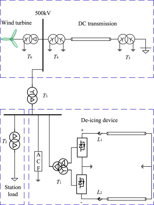
FIGURE 1. DC de-icing diagram.
The top half of the schematic diagram shows the high voltage transmission of the large-scale wind farm. T4 and T5 are the transformers part of the high voltage transmission. The second part includes the DC de-icing device and the station power load of T2, such as the cooling pump of the converter valve. The power for the de-icing device is supplied by the wind turbine and step-down transformer T3. An alter current filter (ACF) and the transformer T1 for the station load is connected to the bus which supplies power to the de-icing device. T1 is the three-winding converter transformer of the DC de-icing device, which follows a twelve-pulse converter and smoothing reactors L1 and L2.
Current Rising Process of the DC De-Icing Device
Comparing with the substation load, the DC de-icing device has an enormous capacity load, which may even exceed the total power consumption of other loads at the substation. To reduce the adverse impact of starting the DC de-icing device, the DC de-icing device with large capacity has a current rising process time t after starting. This duration is related to the size of the rated current and the increasing speed of the control system which ranges from a few seconds to a few minutes. As shown in Figure 2, the current reaches the rated value i0 and enters the steady-state operation process after a certain time t2. If there is an abnormal grounding point on the insulated overhead ground wire, the transverse differential protection or overcurrent protection may detect the fault and block the converter valve during the power rising of the DC de-icing device.
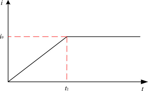
FIGURE 2. The rising current.
Fault Characteristics in the Isolated Ground Wire
To maintain the lightning protection of grounding wires for the isolated grounding wires, there is a large number of grounding switches on the towers of the transmission lines that need de-icing. If grounding wires require de-icing, all grounding switches are open, breaking the connection between the earth and ground wires. Grounding switches are closed if no de-icing is required, to equal the potential of ground wires to the earth. The abnormal grounding point may appear in the isolated ground wire if any grounding switches are not open. Furthermore, the abnormal grounding points of the isolated ground wires of EHV transmission lines during the de-icing can be divided into:
1) an abnormal grounding point in the single insulated ground wire.
2) Abnormal grounding points in both insulated ground wires on the same tower.
3) Abnormal grounding points in both insulated ground wires on the different towers.
Although the fault characteristics induced by abnormal grounding points are varied in different cases, all abnormal grounding points can cause de-icing devices to fail to connect to a part of ground wires, meaning the de-icing device is not able to melt the whole ground wire. The current of the DC de-icing device is under the control of the constant current control of the de-icing device, so the magnitude of the output current of both poles is very similar. The voltage magnitude of both poles may be different if the equivalent resistance of poles is various. Furthermore, the output power of each pole is proportional to the resistance of ground wires, which is the load of each pole. In other words, the abnormal grounding points on the isolated ground line may cause varied output power in different poles. Therefore, the distance from abnormal grounding points to the rectifier can be calculated by the different output energy by poles.
Unlike faults in normal transmission lines, the abnormal grounding point in the ground wires usually occurs before the operation of the DC de-icing device. Thus, fault characteristics can be detected during the rising of the output current.
An Abnormal Grounding Point in the Single Insulated Ground Wire
An abnormal grounding point occurs in the isolated ground wire which is connected to the positive pole as shown in Figure 3.
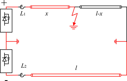
FIGURE 3. An abnormal grounding point in the single insulated ground wire.
The equivalent resistance of the grounding switch is quite small, so the current of the positive pole transmits to the earth without propagating to the terminal of the grounding wire. There is only one abnormal grounding point in the positive isolated ground wire before the de-icing device works, hence the bipolar resistance can be written as
where R+ and R− are the resistance of positive and negative poles; l stands for the length of the ground wire; x denotes the distance from the abnormal grounding point to the rectifier; ρ refers to the resistivity of the ice melting line.
The power of the de-icing device poles can be calculated by
where p+ and p− represents the output power of positive and negative poles, respectively; i+ and i− mean.n the direct current of the positive and negative poles, respectively.
Due to the influence of the current control of the DC de-icing device, the current of positive and negative poles keeps the same absolute value even though the loads of these two poles are different. As a result, the positive pole output voltage is less than the negative pole output voltage in Figure 3. The transverse differential protection can be triggered by detecting the voltage imbalance between two poles before the output power reaches a steady state.
The distance from the abnormal ground point in a single line to the de-icing device can be expressed by
where Wj1 represents the energy consumption of one pole (j = positive pole or negative pole); t0 means the time of the de-icing device starting; t2 means the time of transverse differential protection triggered; pj denotes the outpower of the faulty pole; W0 represents the rated power consumption. Due to the fixed length of the line, the current rising rate is also basically constant when the line is thawed. W0 can be calculated according to the protection action time and starting time of the de-icing device.
Abnormal Grounding Points in Both Insulated Ground Wires on the Same Position
The schematic diagram of the fault circuit is shown in Figure 4, which indicates the situation of the abnormal grounding points of both poles in the same position.
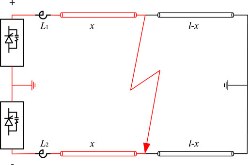
FIGURE 4. Abnormal grounding of bipolar in the same position.
As shown in Figure 4, the voltage amplitude and output power of the positive and negative poles are similar when the abnormal grounding points of both poles occur in the same position. The protection of the DC de-icing device cannot determine whether it has an abnormal grounding point on the ground wire since the output voltage of both poles is identical.
It is necessary to measure the rated value of the output power of the DC de-icing device to compare it with the actual output power of the DC de-icing device. The instantaneous power during the operation of the DC de-icing device can be expressed as follows:
The power of the two poles is the same in this case, so the transverse differential protection will not operate from the start of the DC de-icing device until the current reaches the set value. To identify whether abnormal grounding points occur, the output power of one pole can be selected and compared with the rated energy consumption of startup under normal conditions. The distance between the substation and abnormal grounding points can be calculated as
where Wj2 means start-up power consumption of any bipolar pole; t2 denotes the time that the de-icing device reaches the steady state.
Abnormal Grounding Points in Both Insulated Ground Wires on the Different Position
The schematic diagram of abnormal grounding points in two insulated overhead ground wires with different positions is shown in Figure 5.
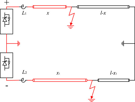
FIGURE 5. Abnormal grounding at different bipolar positions.
In Figure 5, although the output current amplitudes of the bipolar are the same, the voltage amplitudes and output power of the positive poles are both smaller than the negative pole, due to the smaller effective load of the positive pole than that of the negative pole. Furthermore, the output power of both poles is less than the normal state. The instantaneous output power of the DC de-icing device can be expressed as Eq. 9.
The distance between abnormal grounding points is calculated by utilizing the ratio of the rated output power from the starting to the protection action and the actual output power.
where Wj3 represents the start-up power consumption of the ground fault pole; xj stands for the distance between the abnormal grounding point of the positive and negative poles and the outlet of the rectifier.
Simulation Analysis
Simulation Modeling
The simulation model is built in PSCAD/EMTDC according to the structure diagram shown in Figure 1. The parameters are taken from the DC de-icing device of the converter station, as shown in Table 1.

TABLE 1. Component parameters of ice melting model.
An Abnormal Grounding Point in the Single Insulated Ground Wire
An abnormal grounding point is placed in the insulated overhead ground wire and connected, 150 km from the DC de-icing device. The output power of the positive and negative poles after the DC de-icing device is started, are shown in Figure 6.
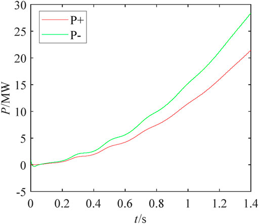
FIGURE 6. Single-pole abnormal grounding instantaneous power.
Under the control of de-icing devices, the output current of both poles keeps rising with a constant speed, which also induces an improvement in the output power. Meanwhile, the equivalent resistance of the positive pole is smaller than the negative pole, since the isolated ground wire connected to the positive pole with an abnormal grounding point is shorter than the normal isolated grounding point connected to the negative pole. Furthermore, the output power is proportional to resistance due to the constant current of the de-icing devices, so the output power of the positive pole is smaller than that of the negative pole. The waveform in Figure 6 presents the different rising speeds of the output power of both poles with an abnormal grounding point in the single insulated overhead ground wire.
Due to the imbalance of the output power of the two poles, the transverse differential protection of de-icing devices can be triggered to lock the converter and switch off the current. The distance between the abnormal grounding point and the deicing device is 150.84 km.
Table 2 was obtained by simulating abnormal grounding points in different positions to verify the accuracy of the proposed location method. It can be concluded that the location method is feasible for the abnormal grounding point in the single insulated ground wire since the location error is really small.

TABLE 2. Single-pole abnormal grounding distance measurement.
Abnormal Grounding Points in Both Insulated Ground Wires on the Same Tower
Both insulated ground wires are assumed to be abnormally grounded on the same tower, which is 150 km from the DC de-icing device. After the DC de-icing device is started, the power of the positive and negative poles is shown in Figure 7A,B. Combining Eq 7 and Eq 8, can calculate the location of the abnormal grounding point, which is 149.74 km. Two abnormal grounding points on the same tower are not able to cause different output power of the poles of the DC de-icing device. Thus, the output power of the two poles is approximately the same after a long period of power rising, which cannot trigger the transverse differential protection.
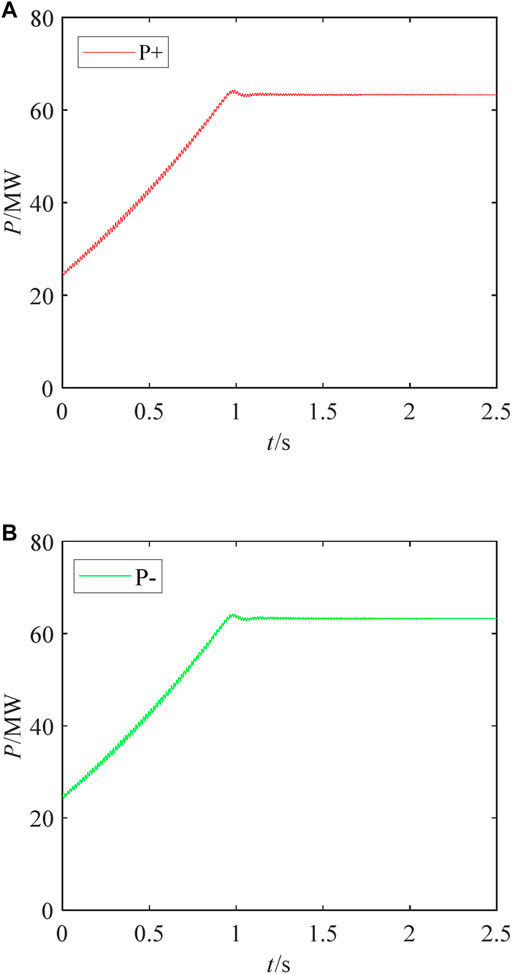
FIGURE 7. Instantaneous power of abnormal grounding in the bipolar identical position.
Therefore, after reaching the constant power state, the comparation of the rated power should be applied to estimate the actual length of the two poles to prevent the incomplete de-icing of the ground wires due to abnormal grounding.
A large number of simulations were carried out to test the robustness of the proposed location method. Due to the page limit, some of them are illustrated in Table 3. The location method is suitable for the abnormal grounding point in the insulated ground wire due to the small number of errors of the location method.
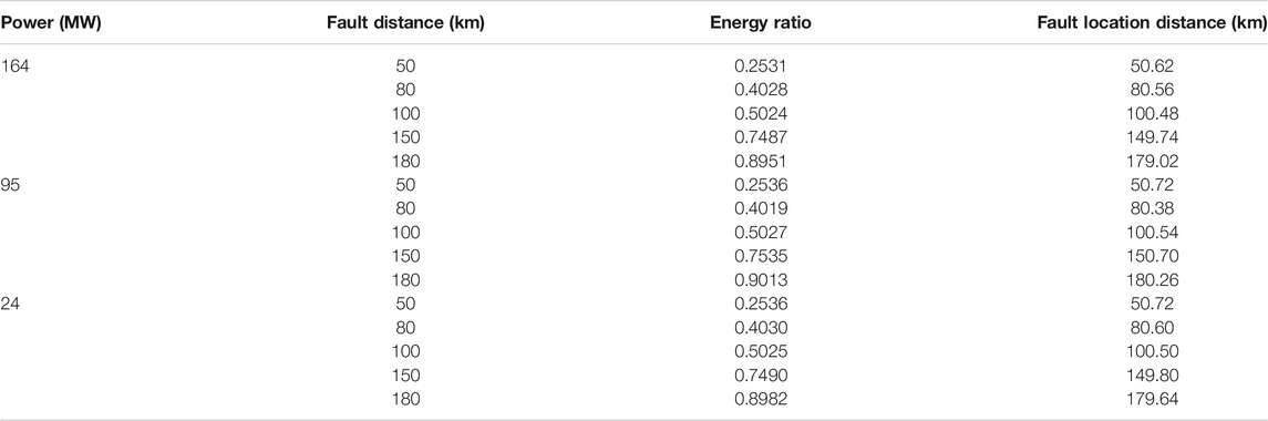
TABLE 3. Bipolar same position abnormal grounding distance measurement.
Abnormal Grounding Points in Both Insulated Ground Wires on the Different Tower
Both insulated ground wires are assumed to be abnormally grounded on the different towers, which are 100 and 180 km away from the DC de-icing device, respectively. The power of the positive and negative poles after the DC de-icing device is started, is shown in Figure 8.
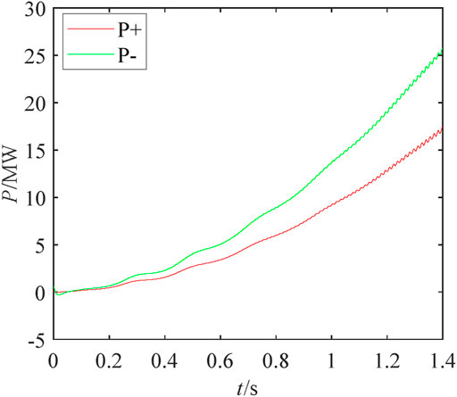
FIGURE 8. Instantaneous power of abnormal grounding at different positions of bipolar.
Two abnormal grounding points on various towers cause different equivalent resistance of the poles of the DC de-icing device, which further leads to the imbalance output power of poles. Therefore, the output power of the two poles is significantly different while the power is rising. The location of abnormal grounding points acquired by Eq. 10 and Eq. 11 are 120.38 and 179.60 km, respectively.
Table 4 is acquired by simulating abnormal grounding points in the different positions of two poles to verify the accuracy of the proposed location method. This location method is feasible for the abnormal grounding points in both insulated ground wires on the different towers. In Table 4, x1.
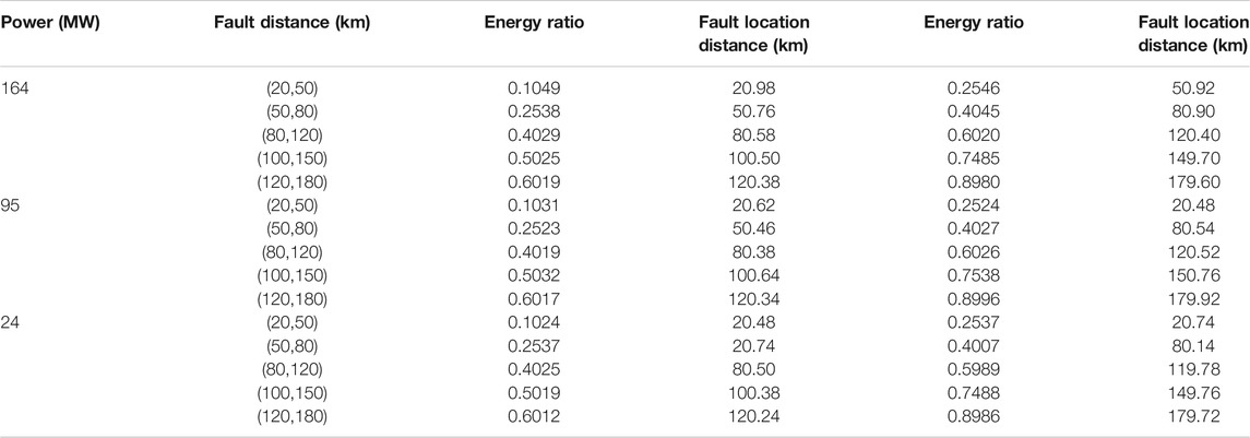
TABLE 4. Abnormal ranging at different bipolar positions.
Conclusion
1) There is a long period of current rising for the reduction of the adverse impact of the DC de-icing device with large capacity, hence the abnormal grounding point may trigger the transverse protection of the de-icing device.
2) The resistance of transmission lines is fairly distributed, so the energy consumption of the positive and negative poles during the current rising can be applied to locate the abnormal grounding point.
Data Availability Statement
The original contributions presented in the study are included in the article/supplementary material, further inquiries can be directed to the corresponding author.
Author Contributions
YW: experiment design and article writting NC: simulation model design in PSCAD/EMTDC XM: fault location scheme verification ZY: article writting and reference searching.
Funding
This work is supported by China Southern Power Grid Project (No. 0109002021030103SJ00002).
Conflict of Interest
YW, NC, XM and ZY were employed by China Southern Power Grid EHV Transmission Company.
The authors declare that the research was conducted in the absence of any commercial or financial relationships that could be construed as a potential conflict of interest.
References
Bin, W., and Lin, Y. (2020). Error Analysis of Single Terminal Traveling Wave Fault Location for HVDC Transmission Lines. Electrotechnical Appl. 39 (10), 33–38.
Chen, Y., Yin, J., Li, Z., and Wei, R. (2021). Single-Line-to-Ground Fault Location in Resonant Grounded Systems Based on Fault Distortions. IEEE Access 9 (9), 34325–34337. doi:10.1109/access.2021.3061211
De Oliveira Neto, J. A., Sartori, C. A. F., and Junior, G. M. (2021). Fault Location in Overhead Transmission Lines Based on Magnetic Signatures and on the Extended Kalman Filter. IEEE Access 9 (9), 15259–15270. doi:10.1109/access.2021.3050211
Feng, X., Qi, L., and Pan, J. (2016). “A Novel Fault Location Method and Algorithm for DC Distribution protection,” in 2016 IEEE Industry Applications Society Annual Meeting, Portland, October 2–6, 2016 (IEEE), 1–5.
Gao, X., Huang, W., and Tai, N. (2020). “Fault Location Method for MMC Multi-Terminal DC Distribution Network Using Transient DC Currents,” in 2020 4th International Conference on HVDC (HVDC), Xi'an, China, November 6–9, 2020 (IEEE), 961–965.
Guang, S., Yang, W., and Feng, X. (2020). Research on an Improved Double-Terminal Traveling Wave Fault Location Method for UHVDC Project. Power Syst. Prot. Control. 48 (14), 113–120.
Guo, B., Song, G., Hou, J., Wu, L., and Han, W. (2019). A Single-Ended Fault Location Method for DC Line Based on Active Signal. 2019 IEEE 8th International Conference on Advanced Power System Automation and Protection (APAP), Xi'an, China, October 21–24, 2019 (IEEE), 1503–1507.
Haleem, N. M., and Rajapakse, A. D. (2019). “A Single Pole to Ground Fault Location Method for HVDC Transmission Lines Based on Coupling Characteristics,” in 15th IET Int. Conf. AC DC Power Transm. (ACDC 2019), Coventry, UK, February 5–7, 2019 (Winnipeg, MB: IET), 1–6.
Hao, W., Peng, S., and Lu, J. (2015). Research on DC Ice-Melting Technologies for 500kV AC Transmission Lines. 2015 5th International Conference on Electric Utility Deregulation and Restructuring and Power Technologies. DRPT, Changsha, China, November 26–29, 2015 (IEEE), 1663–1666.
Jiazheng, L., Siguo, Z., Bo, L., Yanjun, T., Xiudong, Z., Qinjun, H., et al. (2016). Ice-melting Device with Function of Reactive Power Compensation and Active Filtering. High Voltage Eng. 42 (07), 2207–2214.
Juanjuan, W., Chuang, F., Yiping, C., Hong, R., Shukai, X., Tao, Y., et al. (2012). Research and Application of DC De–icing Technology in China Southern Power Grid. IEEE Trans. Power Deliv. 27 (3), 1234–1242. doi:10.1109/TPWRD.2012.2191576
Kai, L., Zhengyou, H., and Xiaopeng, L. (2013). Fault Location of HVDC Transmission Line Based on the Natural Frequency of Traveling Wave. Automation Electric Power Syst. 37 (03), 104–109.
Lei, A., Dong, X., Shi, S., and Wang, B. (2015). “A Novel Current Travelling Wave Based Single-Ended Fault Location Method for Locating Single-Phase-To-Ground Fault of Transmission Line,” in 2015 50th International Universities Power Engineering Conference. (UPEC), Stoke on Trent, UK, September 1–4, 2015 (IEEE), 1–6.
Miao, L., Fang, J., Wen, J., and Luo, W. (2013). Transient Stability Risk Assessment of Power Systems Incorporating Wind Farms. J. Mod. Power Syst. Clean. Energ. 1 (2), 134–141. doi:10.1007/s40565-013-0022-2
Shukr, M., Thomas, D. W. P., and Zanchetta, P. (2012). “VSC-HVDC Transmission Line Faults Location Using Active Line Impedance Estimation,” in 2012 IEEE International Energy Conference and Exhibition (ENERGYCON), Florence, Italy, September 9–12, 2012 (IEEE), 244–248.
Sun, P., Chen, S., and Zhang, S. (2011). “The Study of DC Melting Ice for Overhead Ground Wire,” in 2011 International Conference on Electronics, Communications and Control (ICECC), Ningbo, China, September 9–11, 2011 (IEEE), 2960–2963.
Wangsheng, X., jiang, H., and Yongliang, Y. (2016). Study on Location Technology of Overhead Ground Wire Ice Melting Fault Based on Traveling Wave Method. Mech. Electr. Inf. 97 (15), 94–95.
Wu, J.-Y., Lan, S., Xiao, S.-J., and Yuan, Y.-B. (2021). Single Pole-to-Ground Fault Location System for MMC-HVDC Transmission Lines Based on Active Pulse and CEEMDAN. IEEE Access 9 (9), 42226–42235. doi:10.1109/access.2021.3062703
Yuansheng, L., Gang, W., and Haifeng, L. (2015). Time-Domain Fault-Location Method on HVDC Transmission Lines under Unsynchronized Two-End Measurement and Uncertain Line Parameters. IEEE Trans. Power Deliv. 30 (3), 1031–1038. doi:10.1109/tpwrd.2014.2335748
Yunke, Z., Botong, L., and Bin, L. (2017). Ground-fault Location Technology for Extra-high Voltage Transmission Lines during DC De-icing Process. Automation Electric Power Syst. 41 (20), 105–111.
Zasypkin, A., and Shchurov, A. (2020). “Capacitor Protection of Electromagnetic Voltage Transformers in DC Ice Melting Schemes on Overhead Transmission Lines,” in 2020 International Multi-Conference on Industrial Engineering and Modern Technologies (FarEastCon), Vladivostok, Russia, October 6–9, 2020 (IEEE), 1–6.
Zhi, W., and Fangzong, W. (2011). A New Method of Earth Fault Detection in Distribution System. Power Syst. Prot. Control. 39 (20), 48–51.
Zhu, S., Li, B., Tan, Y., Han, Y., Ouyang, F., and Duan, X. (2019a). “Low Harmonic DC Ice Melting Device Capable of Reactive Power Compensation with SVG,” in 2019 IEEE 3rd Conference on Energy Internet and Energy System Integration (EI2), Changsha, China, November 8–10, 2019 (IEEE), pp. 2460–2465.
Keywords: rising of current, de-icing, isolated ground wire, earthing switch, fault location
Citation: Wang Y, Chen N, Ma X and Yang Z (2021) Fault Location Scheme for Abnormal Grounding Point in Isolated Ground Wire of Large-Scale Clean Energy Transmission. Front. Energy Res. 9:702245. doi: 10.3389/fenrg.2021.702245
Received: 29 April 2021; Accepted: 01 June 2021;
Published: 16 July 2021.
Edited by:
Xiaoshun Zhang, Shantou University, ChinaReviewed by:
Xia Fang, Sichuan University, ChinaRui Liang, China University of Mining and Technology, China
Pulin Cao, Kunming University of Science and Technology, China
Copyright © 2021 Wang, Chen, Ma and Yang. This is an open-access article distributed under the terms of the Creative Commons Attribution License (CC BY). The use, distribution or reproduction in other forums is permitted, provided the original author(s) and the copyright owner(s) are credited and that the original publication in this journal is cited, in accordance with accepted academic practice. No use, distribution or reproduction is permitted which does not comply with these terms.
*Correspondence: Yunlong Wang, MjUyODQ2MjM3NUBxcS5jb20=