 Kun Huang1
 Anhui Feng
95% of researchers rate our articles as excellent or good
Learn more about the work of our research integrity team to safeguard the quality of each article we publish.
Find out more
ORIGINAL RESEARCH article
Front. Energy Res. , 25 June 2021
Sec. Smart Grids
Volume 9 - 2021 | https://doi.org/10.3389/fenrg.2021.701873
This article is part of the Research Topic New Solutions for Smart Grids with High-Penetration Distributed Energy Resources View all 19 articles
The current calculation method of fluid–structure interaction (FSI) has a defect for oilimmersed transformers for distributed energy resources (DERs). In order to solve this problem, a calculation method is proposed for the temperature rise of oil-immersed transformers in this article. The vibration of insulating oil is considered in this method. Different from the temperature field model established by FSI, the effect of insulating oil vibration on the temperature field is considered. The structure field is introduced to establish the insulating oil vibration model. The temperature field correction coefficient is introduced by coupling the insulating oil vibration and the natural convection of the insulating oil. The result shows that compared with FSI, the results of the calculation method in this study are consistent with the experiment, and the temperature field distribution in the oil-immersed transformer can be calculated more accurately.
With the increasing demand for energy in industrial production and people’s lives, as well as the contradiction between environmental problems and energy development, exploring how to improve the energy utilization rate on the premise of environmental friendliness has become a topic of common concern all over the world. With the development of microgrids and distributed generation technology, more and more clean energy is used in power systems, which puts forward new requirements for the stability of power grids. The operation state of a power transformer is directly related to the stability of the power grid, and in actual operation, insulation and thermal problems are the key factors affecting the operation state of the transformer. The loss will generate heat during the operation of the transformer, making the temperature rise. The presence of insulating oil will cause the heat accumulation above the core and winding, and the core and winding will locally overheat. Operating at high temperatures for a long time will destroy the insulation layer above the transformer, leading to thermal aging of the transformer, causing insulation breakdown and affecting the stability of the power system. Therefore, it is of great importance to obtain the accurate temperature field distribution in the transformer.
In order to balance the interests of IEO and users, a novel Stackelberg game-based optimization framework is proposed for the optimal scheduling of integrated demand response (IDR). IDR-enabled integrated energy systems with uncertain renewable generations are proposed in Li et al. (2021). A novel optimal scheduling model based on chance-constrained programming (CCP), aimed at minimizing the generation cost, is proposed for a small-scale integrated energy system (IES) with CHP units, thermal power units, renewable generations, and representative auxiliary equipment (Li et al., 2020).The 2D simulation model was established in Liu et al. (2017) for the simulation analysis of the overall temperature rise of oil-immersed transformers by means of mixed numerical calculation. A method for transformer temperature field calculation was proposed in Liao et al. (2015) on the basis of the finite element method and finite volume method, in which a three-phase three-column transformer is calculated and analyzed by the establishment of the electromagnetic– fluid–temperature field coupling model. The effectiveness of the short-circuit method and regression analysis method was verified by Yang et al. (2011). Investigation of the effect of sulfur corrosion on the characteristics of transformer cellulosic insulation was proposed in Gao et al. (2020), and the results were compared with those of fluent software to verify the effectiveness of the method. Xia et al. (2017) proposed a method for calculating the temperature rise of transformer winding, which can effectively tackle the problem of low experimental efficiency of winding temperature rise.
At present, the loss of transformer and the hot spot temperature rise of winding are analyzed in most articles. However, the temperature field of an oil-immersed transformer, especially the calculation of the overall temperature rise, is seldom mentioned (Wang et al., 2017; Lin et al., 2004). Due to the existence of insulating oil, convective heat dissipation is the main heat dissipation mode of an oil-immersed transformer. For coupled heat transfer, the thermal boundary conditions are dynamically determined by the heat exchange process, and there is no need to specify them in advance (Wu et al., 2012; Zhang et al., 2014). However, the FSI calculation is the distribution of the convective heat transfer temperature field in the case of bulk rest of the transformer, tending to focus on the flow velocity in the case of natural convection or forced convection. Generally, it is suitable enough to calculate the heat dissipation of dry transformer air. Given that the insulating oil is much denser than air, the effect of forced vibration of the insulating oil on the temperature field caused by the vibration of the transformer body needs to be considered, making the calculation result closer to the real value.
In order to improve the stability of distributed energy grid operation and maintain the operation safety of the power transformer, considering that the density of insulating oil is much higher than that of air, the influence of forced vibration of insulating oil on the temperature field caused by the transformer body’s vibration needs to be considered. Therefore, this article proposes a calculation method of transformer temperature rise considering the influence of vibration of insulating oil. An oil-immersed transformer can be an example: A multiphysical coupling model of an electromagnetic–structural–fluid–temperature field is established. The distribution of the temperature field in an oil-immersed transformer is analyzed by means of multiphysical field coupling simulation and verified by experiments. The experimental results show that the error of the model is reduced by 3.35%.
The oil-immersed transformer model and technical parameters adopted in this study are shown in Figure 1 and Table 1.
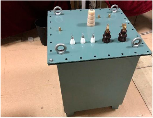
FIGURE 1. Oil-immersed transformer model.
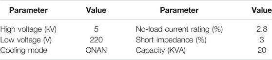
TABLE 1. Transformer technical parameters.
As shown in Figure 2, we only consider the convective heat dissipation of insulating oil based on FSI, namely, the turbulent layer in Figure 3. In the turbulent layer, the insulating oil carries away heat by flowing, playing the role of heat dissipation. However, the laminar flow layer still exists on the turbulent layer and the transformer’s surface. Due to the viscous effect of the fluid, the flow velocity of the laminar flow layer is close to zero, and the temperature changes rapidly in the normal vector direction of the laminar flow layer. The laminar flow layer will greatly hinder the heat dissipation effect of the turbulent layer. The influence of the vibration of the insulating oil on the temperature field is considered, which is caused by the vibration of the wall surface, improving the heat dissipation effect by disturbing the laminar flow layer while increasing the flow velocity of the turbulent layer. Therefore, the vibration of the insulating oil is first calculated and then explained in this article.
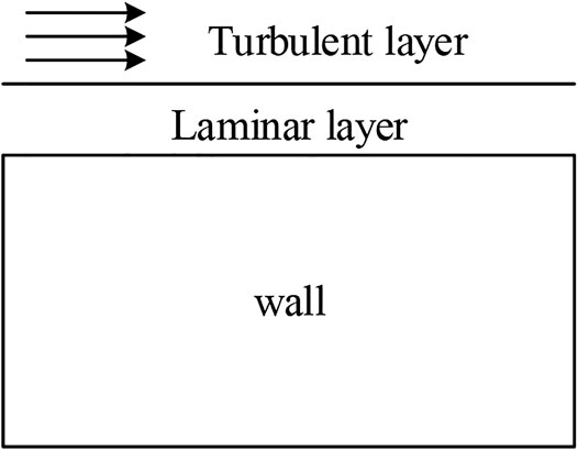
FIGURE 2. Schematic diagram of insulating oil vibration.
FIGURE 3. Insulating oil vibration propagation.
Considering the influence of vibration on the fluid field, the fluid travels from the transformer body to the tank wall as a pressure wave, which is manifested as fluid vibration. The surface pressure generated here is the key to coupling the fluid field of insulating oil vibration with the structural field of the transformer body’s vibration. The propagation formula is as follows (Zhang et al., 2018):
where
When the vibration wave in the insulating oil is transferred to the surface of the oil tank, the wave impedance of the insulating oil is smaller than that of the tank wall, so the transfer wave will reflect as shown in Figure 3. At the same time, the hydraulic pressure formed by the gravity of the insulating oil itself will also suppress the vibration of the transformer.
It can be seen that the reflected pressure wave is still a longitudinal wave, but this time, the phase difference is 180 degrees, and the subsequently transmitted vibration wave interacts with the disturbance. The core and winding through which the vibration wave passes can no longer remain in phase of zero, indicating that the insulating oil vibration wave phase is no longer consistent with the vibration source phase. Phase difference of the
Table 2 shows the physical property parameters of the transformer’s insulating oil. In order to analyze the influence of insulating oil vibration on the suppression effect of the transformer body’s vibration, in line with the analysis of transformer vibration, vibration fluid–solid interaction is adopted to analyze the vibration of the transformer’s insulating oil, as shown in Figure 4. As can be seen, the bottom of the transformer core is based on the fixed constraint, and the vibration of the insulating oil is dominated by the core column and the top one.

TABLE 2. Insulating oil property parameters.
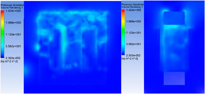
FIGURE 4. Insulating oil vibration.
As shown in Figure 5, the transformer is separated and the vibration of the winding and the core is measured separately by the acceleration sensor. In this experiment, the self-designed distributed feedback laser (DFB) fiber Bragg grating sensor is used for vibration measurement to avoid electromagnetic interference of the traditional piezoelectric sensor and overvoltage damage of the sensor since the sensor needs to have direct contact with the surface of the transformer.
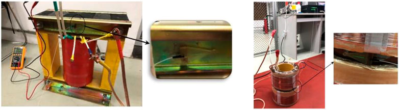
FIGURE 5. Vibration experiment of DFB.
As shown in Figure 6, the measured result of winding vibration acceleration is smaller than that of the iron core, indicating that the vibration of the transformer is dominated by the magnetostriction of the iron core, and then the vibration calculation is dominated by the iron core under normal circumstances, which is consistent with the results shown in Figure 4. Under normal circumstances, the vibration is dominated by iron core.
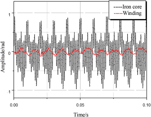
FIGURE 6. DFB vibration experiment waveform.
The reaction force will be produced by the vibration of the insulating oil, which can restrain the vibration of the transformer and reduce the amplitude of transformer vibration. As the vibration source of the insulating oil, the vibration of the transformer is essential for its accurate calculation. Therefore, the effect of oil damping on vibration is calculated by introducing a percentage coefficient of vibration suppression:
where
As shown in Figure 7, the percentage coefficient
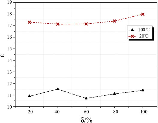
FIGURE 7. Correction coefficient vibration influence diagram.
It should be noted that the ε is significantly affected by temperature. It can be seen in Figure 7 that its value at different temperatures varies greatly because the wave pressure and viscous impedance in the fluid are closely related to the hydrodynamic viscosity. Temperature has a significant effect on the dynamic viscosity of insulating oil and the modulus of silicon steel. Only considering the influence of these factors can help accurately calculate the vibration displacement of the oil-immersed transformer. Therefore, the influence of temperature on vibration model modification should be further considered.
As shown in Figure 8, by simulating the correction coefficient at different temperatures and keeping the vibration intensity constant, it can be noted that there is an approximately linear relationship between the temperature and the correction coefficient
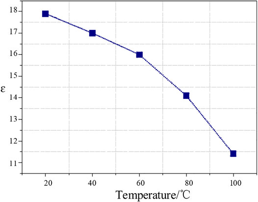
FIGURE 8. Correction coefficient ε temperature influence diagram.
Through formula (2), the value of
where
It can be found that considering the insulating oil vibration for the transformer vibration suppression model is also a function of temperature. With the increase in temperature, the vibration suppression effect of the insulating oil on the transformer becomes weaker and weaker due to the change in the physical parameters of the insulating oil with the temperature change. However, based on the calculations, the vibration of the insulating oil itself becomes more intense as the temperature increases. The vibration of the insulating oil can be accurately calculated with the suppression coefficient.
The influence of insulating oil vibration on the transformer temperature field is reflected in the influence on the surface heat dissipation coefficient (Yang and Tao, 2006). In general, when calculating convective heat dissipation by fluid–structure interaction, only the natural convective heat transfer generated by viscous volume expansion force is considered, while the fluid vibration acceleration generated by pressure resultant force is ignored. The formula is as follows (Tian et al., 2016):
where
In this study, the vibration velocity of the insulating oil is coupled with the natural convection velocity, and then the vibration velocity of the insulating oil is coupled with the temperature field on the basis of the natural expansion heat convection. The convective heat transfer coefficient of the transformer surface considering the vibration of the insulating oil can be expressed as follows:
where
According to formula (4), the heat dissipation coefficient is directly proportional to the temperature rise and fluid flow velocity. The change of fluid velocity will change the temperature field. The fluid flow velocity of the insulating oil is not only composed of the natural buoyancy caused by thermal expansion, but also composed of the vibration velocity caused by the vibration of the insulating oil. According to the above calculation results of vibration of insulating oil, the comparison of two oil flow velocities when the temperature rise reaches 60°C is shown in Figure 9. The velocity of oil disturbed by the insulating oil is obviously lower than that of oil under natural convection.
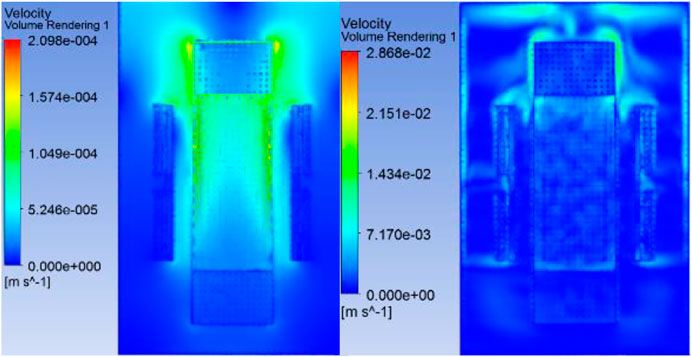
FIGURE 9. Comparison of heat transfer oil disturbance and natural convection oil flow rate.
The vibration of the insulating oil exerts a direct impact on the temperature field, without an impact on the transformer loss directly. However, it is difficult to calculate the overall distribution of the temperature field of the transformer after the coupling structure field, so the loss can be modified by formula (6) to achieve the equivalent correction of the influence of vibration on the temperature field:
Considering the influence of the vibration of the insulating oil on the temperature field, the temperature correction coefficient
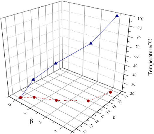
FIGURE 10. Heat transfer oil influence coefficient β.
The iron loss is divided into three basic loss components: hysteresis, eddy current, and abnormal loss (Yang and Tao, 2006; Zou et al., 2010). In most cases, the extra loss is ignored. The classical trinomial formula is usually used to calculate
where
AC copper loss can be equivalent to the composition of DC winding copper loss and eddy current loss (Xue et al., 2018):
Transformer windings are mostly flat copper wires. The skin effect and proximity effect of the flat copper wire windings are shown in Figure 11.
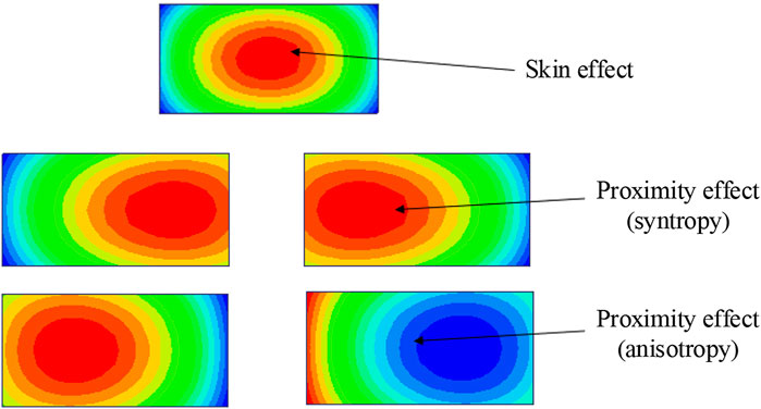
FIGURE 11. Skin effect and proximity effect.
By ignoring the influence of eddy current redistribution on the electric field distribution, the average loss in conductors per unit length can be estimated (Lou and Li, 2016; Tian et al., 2016):
where
The high voltage side is a round copper wire winding, while the low voltage side is a flat copper wire winding. Although the distribution law of current density is the same, the difference in the shape makes the degree of skin effect and proximity effect different, resulting in different increase rates of equivalent resistance. Figure 12 shows the measurement of the winding equivalent resistance using LCR.
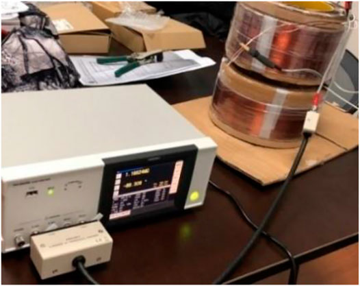
FIGURE 12. Winding AC equivalent resistance experiment.
The results indicate that there is almost no difference in the growth rate of equivalent resistance between the two wires at low and medium frequencies, and the value slightly increases at high frequencies, but the increase is limited. Therefore, a unified model is adopted to calculate the equivalent resistance of the two wires.
There exists a big error of iron loss calculated by the ordinary trinomial formula. For the trinomial formula, temperature will directly affect the coefficient values of core loss. Notably, there are few studies on the influence of temperature on the loss of silicon steel at home and abroad, and the loss data of silicon steel with the influence of temperature are not perfect. The missing material data of the silicon steel must be obtained directly from experiments.
The temperature model of a silicon steel sheet is introduced to correct the coefficient of the trinomial formula, and the temperature feedback model is used for two-way interaction calculation, thus reducing the loss error (Tian et al., 2016):
where
The influence of temperature on iron loss can be obtained by measuring two sets of data, which can effectively solve the problem of imperfect material parameters of the silicon steel sheet. The correlation coefficient is obtained by using the no-load test of iron core as shown in Figure 13 (
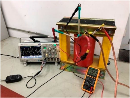
FIGURE 13. Transformer no-load experiment.
The temperature simulation results of the electromagnetic–structural–fluid–temperature field of the multiphysical field interaction transformer filled with insulating oil established by considering the vibration correction model of the insulating oil are shown in Figure 14, and the oil temperature at the upper end of the transformer is obviously higher than that at the lower end.
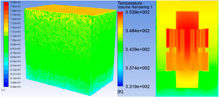
FIGURE 14. Transformer temperature field (insulating oil vibration model).
In order to verify the influence of insulating oil vibration on transformer temperature, the basic temperature of the transformer is changed by changing the filling amount of the insulating oil. When the filling amount of the insulating oil is 80 and 100%, the experimental data and simulation data are compared, as shown in Table 3. Experiments for temperature rise to the top of the oil temperature in rated conditions have been measured. The upper insulating oil temperature of 55.2 and 54.75 °C in the model of the electromagnetic–structural–fluid–temperature field interaction correction, only considering the 57.3 and 56.41°C in the model of three physical field electromagnetic–fluid–temperature field of fluid–solid interaction, there is a difference. The temperature distribution does not change, but the difference between the upper insulating oil temperature rises by about 2.1 and 1.6°C. It can be seen that the error of model construction in this study is lower, with a temperature rise difference of 9.2 and 9.5%, which is reduced by 3.5 and 3.35%.
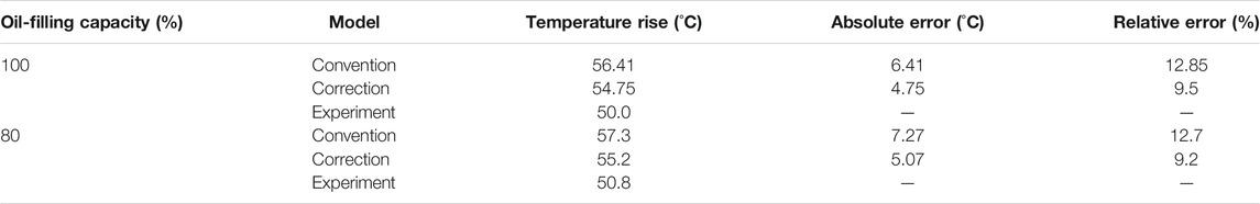
TABLE 3. Corrected results comparison.
The multiphysical interaction model of the electromagnetic–structural–fluid–temperature field considering the vibration of the insulating oil is closer to the real value than the traditional FSI model. The multiphysical coupling method considering the influence of the vibration of the insulating oil is more reliable. It can be extended to all types of oil-immersed power transformers for the reason proposed in this article: The calculation method considers the influence of insulating oil vibration on the internal temperature field of the oil-immersed transformer as a function of temperature.
In this article, a more accurate method is proposed to calculate the temperature field of the transformer considering the vibration of the insulating oil. Taking an oil-immersed transformer as an example, the multiphysical coupling model of the electromagnetic–structural–fluid–temperature field considering the vibration of the insulating oil can be used to calculate the temperature field of the oil-immersed transformer more accurately. The following conclusions are drawn:
1) A modified model of vibration suppression of insulating oil is established, and a temperature-dependent vibration suppression function of insulating oil is established by introducing the correction coefficient
2) A correction model for the influence of insulating oil vibration on the temperature field is established. As the temperature increases, the influence of heat conduction oil on the temperature field increases. At the same time, the influence of insulating oil vibration on temperature field considered in this study is still a function of temperature through correction coefficients
3) The multiphysical coupling model of the electromagnetic–structural–fluid–temperature field is established to calculate the temperature field of an oil-immersed transformer.
The model of vibration suppression function and the calculation method of temperature field considering the vibration of insulating oil are presented in this article, which is of great significance to prolong the service life of power transformers and maintain the stable operation of distributed energy resource systems.
The original contributions presented in the study are included in the article/Supplementary Material. Further inquiries can be directed to the corresponding author.
The individual contributions of the authors are as follows: data curation, KH; formal analysis, HL; methodology, WW; supervision, XL; validation, LZ; writing (original draft), AF. All authors have read and agreed to the published version of the manuscript.
KH, HL, and WW were employed by Guangzhou Power Supply Bureau Limited.
The remaining authors declare that the research was conducted in the absence of any commercial or financial relationships that could be construed as a potential conflict of interest.
Gao, S., Yang, L., and Ke, T. (2020). Failure Mechanism of Transformer Oil-Immersed Cellulosic Insulation Induced by Sulfur Corrosion. Cellulose 27 (12), 7157–7174. doi:10.1007/s10570-020-03271-x
Li, Y., Wang, C., Li, G., and Chen, C. (2021). Optimal Scheduling of Integrated Demand Response-Enabled Integrated Energy Systems with Uncertain Renewable Generations: A Stackelberg Game Approach. Energ. Convers. Manage. 235, 113996. doi:10.1016/j.enconman.2021.113996
Li, Y., Wang, C., Li, G., Wang, J., Zhao, D., and Chen, C. (2020). Improving Operational Flexibility of Integrated Energy System with Uncertain Renewable Generations Considering thermal Inertia of Buildings. Energ. Convers. Manage. 207, 112526. doi:10.1016/j.enconman.2020.112526
Liao, C., R, J., Liu, C., et al. (2015). Comprehensive Analysis of 3-D Electromagnetic-Fluid-thermal fields of Oil-Immersed Transformer. Electr. Power Autom. Equip. 35 (9), 150–155. doi:10.16081/j.issn.1006-6047.2015.09.024
Lin, D., Zhou, P., Fu, W. N., Badics, Z., and Cendes, Z. J. (2004). A Dynamic Core Loss Model for Soft Ferromagnetic and Power Ferrite Materials in Transient Finite Element Analysis. IEEE Trans. Magn. 40 (2), 1318–1321. doi:10.1109/TMAG.2004.825025
Liu, G., Jin, Y., Ma, Y., et al. (2017). Numerical Analysis of Fluid Field and Temperature Field of Oil-Immersed Transformer. Transformer 54 (5), 22–26. doi:10.19487/j.cnki.1001-8425.2017.05.007
Lou, Y., and Li, B. (2016). Methods for Reducing the Loss Caused by the Eddy Current in Electromagnetic Railgun Shielding. High Voltage Eng. 42 (6), 1935–1941. doi:10.13336/j.1003-6520.hve.20160401007
Tian, M., Zhu, J., and Song, C. (2016). Temperature Field Simulation of Coal Dry-type Transformer Based on Fluid-Solid Coupling Analysis. High Voltage Eng. 42 (12), 3972–3981. doi:10.13336/j.1003-6520.hve.20161128035
Wahyudi, M., Negara, I. M. Y., Asfani, D. A., Hernanda, I. G. N. S., and Fahmi, D. (2017). “Application of Wavelet Cumulative Energy and Artificial Neural Network for Classification of Ferroresonance Signal during Symmetrical and Unsymmetrical Switching of Three-Phases Distribution Transformer.” in 2017 International Conference on High Voltage Engineering and Power Systems, Bali, Indonesia, Oct 02–05, 2017, (Indonesia: Pendidikan Tnggi Teknik Indonesia; Inst Teknologi Bandung; Inst Teknologi Bandung, STEI; PLN), 394–399. doi:10.1109/ICHVEPS.2017.82258770
Wang, W., et al. (2017). The Calculation Method of Temperature Field of Oil Immersed Transformer with FEM and FVM Combined Method. Electr. Meas. Instrument. (18), 42–47.
Wang, X., Lai, C., Yu, D., Xu, Y., and He, Y. (2019). “Application of Energy Performance Contracting in Distribution Transformer Based on Neural Network Prediction,” in 2019 IEEE 3rd Information Technology, Networking, Electronic and Automation Control Con-ference (ITNEC), 42–46. doi:10.1109/ITNEC.2019.8729195
Wu, X., Shu, N., and Li, H. (2012). Thermal Field Calculation and Analysis of Gas Insulated Busbars Based on Fluid Multiple Species Transport. Proc. CSEE 32 (33), 141–147. doi:10.13334/j.0258-8013.pcsee.2012.33.020
Xia, Y., Zhang, J., and Xie, Q. (2017). Engineering Calculation Method for Winding Temperature Rise of Oil Immersed Power Transformer. High Voltage Apparatus 53 (9), 176–180. doi:10.13296/j.1001-1609.hva.2017.09.030
Xue, S., Feng, J., Guo, S., Peng, J., Chu, W. Q., and Zhu, Z. Q. (2018). A New Iron Loss Model for Temperature Dependencies of Hysteresis and Eddy Current Losses in Electrical Machines. IEEE Trans. Magn. 54 (1), 1–10. doi:10.1109/TMAG.2017.2755593
Yang, Z., Wang, L., and Du, J. (2011). Temperature Rise Test of Oil -Immersed Power Transformer and its Calculating Method. Transformer 38 (6), 15–20. doi:10.19487/j.cnki.1001-8425.2001.06.006
Zhang, F., Ji, S., Shi, Y., et al. (2018). Research on Transfoermer Winding Vibration and Propagation Characteristics. Proc. CSEE 38 (9), 2790–2798. doi:10.13334/j.0258-8013.pcsee.170497
Zhang, Q., Lu, X., and Huang, S. (2014). Temperature Rise Calculations of High Density Permanent Magnet Motors Based on Multi-Domain Co-simulation. Proc. CSEE 34 (12), 1874–1881. doi:10.13334/j.0258-8013.pcsee.2014.12.006
Keywords: DERs, correction coefficient, insulating oil, multiphysical interaction, oil-immersed transformer, temperature field
Citation: Huang K, Li H, Wang W, Zhang L, Feng A and Li X (2021) Multi-Field Collaborative of Oil-Immersed Transformer for Distributed Energy Resources Temperature Rise Considering the Influence of Heat Transfer Oil. Front. Energy Res. 9:701873. doi: 10.3389/fenrg.2021.701873
Received: 28 April 2021; Accepted: 17 May 2021;
Published: 25 June 2021.
Edited by:
Yang Li, Northeast Electric Power University, ChinaReviewed by:
Shaoyan Li, North China Electric Power University, ChinaCopyright © 2021 Huang, Li, Wang, Zhang, Feng and Li. This is an open-access article distributed under the terms of the Creative Commons Attribution License (CC BY). The use, distribution or reproduction in other forums is permitted, provided the original author(s) and the copyright owner(s) are credited and that the original publication in this journal is cited, in accordance with accepted academic practice. No use, distribution or reproduction is permitted which does not comply with these terms.
*Correspondence: Xiaohua Li, bGl4aWFvaHVhOTZAMTI2LmNvbQ==
Disclaimer: All claims expressed in this article are solely those of the authors and do not necessarily represent those of their affiliated organizations, or those of the publisher, the editors and the reviewers. Any product that may be evaluated in this article or claim that may be made by its manufacturer is not guaranteed or endorsed by the publisher.
Research integrity at Frontiers
Learn more about the work of our research integrity team to safeguard the quality of each article we publish.