 Nobuyuki Gokon1*
 Chew Shun Jie2Yuya Nakano2Shogo Okazaki2Tatsuya Kodama1Tsuyoshi Hatamachi1
 Selvan Bellan1
- 1Dep. of Chemistry and Chemical Engineering, Faculty of Engineering, Niigata University, Niigata, Japan
- 2Graduate School of Science and Technology, Niigata University, Niigata, Japan
A copper–germanium alloy (Cu–Ge alloy) was examined as a phase change material, at temperatures exceeding 600°C, for latent heat storage in solar thermal applications. First, the thermo-physical properties of the Cu–Ge alloy were examined using differential scanning calorimetry, thermomechanical analysis, and laser flash analysis. Second, to evaluate the thermal response and reliability of the Cu–Ge alloy, the cyclic properties of thermal charge/discharge were examined under various thermal conditions. The alloys obtained after the tests were examined for their chemical compatibility with the stainless steel container using an electron probe micro analyzer. The elemental distribution of each Cu–Ge alloy was evaluated using cyclic performance tests. Finally, the chemical compatibility of the Cu–Ge alloy was evaluated using a high-temperature test with candidate materials of a phase change material container vessel [stainless steel (SUS310S), Inconel625, silicon carbide (SiC), and alumina (Al2O3)]. The Cu–Ge alloy exhibited significant potential as a latent heat storage material in next-generation solar thermal power plants because it demonstrates various advantages, including a superior storage capacity at a temperature of 644°C, temperature coherence to the phase diagram, a quick thermal response, satisfactory cyclic behavior of charge/discharge modes, a thermodynamically stable metallographic structure, and non-reactivity with container ceramic materials (SiC and Al2O3).
Introduction
Renewable energy sources are attractive alternatives to fossil fuels because of their promising social, environmental, and economic benefits. The Sustainable Development Scenario of the International Energy Agency (IEA) outlook 2020 predicted that CO2 emissions will fall to less than 27 billion tonnes in 2030, and low-carbon electricity will account for almost two-thirds of the world's total electricity generation (International Energy Agency (IEA), 2020). Solar energy is one of the most environmentally friendly energy sources, and the milestones for solar energy exploitation are energy capture, energy conversion, and energy storage. Solar energy can be harnessed in two different ways, namely, photovoltaic cells and thermal conversion systems (Goswami, 2015).
Concentrating solar power technologies (CSPs) convert sunlight into thermal power, which is traditionally used as a heat source for power generation by thermodynamic cycles (Islam et al., 2018). CSP technology has the advantage of higher utilization efficiency of solar energy, extension of the energy operating period from day to night, or from sunny to cloudy weather due to the capability to store energy in the thermal storage system and use it when required (Cohen, 2008; Skumanich, 2010; Stoffel et al., 2010). In accordance with relevant physicochemical mechanisms, the working principles of thermal energy storage (TES) are typically classified into three types: sensible heat storage, latent heat storage, and thermochemical heat storage (Gil et al., 2010; Pelay et al., 2017).
Molten salts are excellent for use in liquid sensible TES and as heat transfer fluids (HTFs) because of their thermal stability at high (generally over 500°C) temperatures. They are commonly utilized in modern central tower CSP technology (Kuravi et al., 2013). One of these molten salts, solar salt (60 wt% NaNO3-40 wt% KNO3), has proven successful even for TES in the GWh-scale at an operating temperature range of 290–560°C. In current CSP technologies, the highest temperature of the heat source is largely restricted by the thermal decomposition temperature of the HTF (Xu et al., 2018). In addition, corrosion by molten salts of the pipe material and storage tank is an important factor requiring improvement. To increase solar-to-power efficiency in current CSP plants, coating technology (Agüero et al., 2019) allowing the control of moderate corrosion degradation, using low-cost steel instead of expensive Ni-base alloys, and enhancing the thermal stability limit of solar salt to 600°C or above temperature (Bonk et al., 2019) by controlling the salt chemistry of corrosive species have been extensively studied. The high-temperature limit of the molten salt directly affects the volumetric thermal storage capacity and efficiency of the coupled thermodynamic cycle. Thus, HTFs with high thermal durability at high temperatures are required for next-generation CSP.
The cost of CSP in 2018, with an average levelized cost of electricity (LCOE) of 0.185 USD/kWh (IRENA, 2018), remain uncompetitive with other renewable energy technologies (wind and solar PV). However, next-generation CSP tower technologies are expected to significantly lower this figure to 0.08–0.11 USD/kWh by 2025 (IRENA, 2016), mainly because the utilization of high temperature (>700°C) receivers will unlock the possibility of improving power block efficiency. The Generation three Concentrating Solar Power (Gen3CSP) program was initiated by the Department of Energy (DOE) to improve commercial viability (Mehos et al., 2017). The Gen3CSP liquid pathway (G3LP) project of the three technology tracks is being developed to increase the operating temperature of CSP plants using liquid heat transfer and storage fluids to 700°C to increase plant efficiencies and reduce the LCOE. One option includes a liquid sodium receiver to collect concentrated thermal energy, a 3-part or ternary mixture of chloride molten salts to store heat, and a supercritical carbon dioxide (sCO2) Brayton cycle to convert it to electricity (Carlson et al., 2020).
Several latent heat storage (LHS) systems using phase change materials (PCMs), between solid and liquid phases, have been identified in molten salts and metals. Molten-salts have been utilized as potential PCMs for TES in CSP applications (Medrano et al., 2010; Kotzé et al., 2013). Most salt-based PCMs suffer from a series of drawbacks, including low thermal conductivity, being highly corrosive in the liquid phase at high temperature, and large volume changes during the phase change (Zhang et al., 2016). Metallic-based PCMs exhibit a rapid thermal response and high operating power owing to their high thermal conductivity, which leads to a decrease in the plant startup time and considerable latent storage capacity owing to the high density of the solid phase, in comparison to salt-based PCMs. In addition, high thermo-mechanical durability and reliability are beneficial for alleviating rapid thermal shocks caused by solar fluctuations and radiation transients (Risueño et al., 2017). These significant features make metallic-based PCMs promising candidates for LHS applications in current and next-generation CSP.
Birchenall and Reichmann (Birchenall and Riechman, 1980), and Farakas and Birchenall (Farkas and Birchenall, 1985) initially reported the possibility of metallic PCMs storing thermal energy by the enthalpy of fusion in binary and ternary eutectic mixtures. Most studies on TES in CSP applications have focused on low melting temperatures of T < 400°C, including Al–Mg–Zn (Khare et al., 2012), Mg–Zn (Blanco-Rodríguez et al., 2014; Rodríguez-Aseguinolaza et al., 2014), Al–Mg–Zn (Sun et al., 2007), Zn–Sn (Adinberg et al., 2010), Zn–Al–Mg (Risueño et al., 2017), Zn–Al (Risueño et al., 2017), Zn–Mg (Risueño et al., 2017), and Al–Sn (Sugo et al., 2013) systems. The potential TESs of metallic PCMs at an upper melting temperature of 600°C, which corresponds to a current central tower CSP using solar salt as the HTF and liquid sensible heat storage include Al–Mg–Zn (Farkas and Birchenall, 1985), Mg–Cu–Zn (Farkas and Birchenall, 1985), Mg–Bi (Fang et al., 2016), Al–Cu (Zhao et al., 2017), Al–Cu–Si (Farkas and Birchenall, 1985), Cu–Mg (El Karim et al., 2019), Al–Si (Wang et al., 2015) systems. The most promising TESs of metallic PCMs that allow their combination with next-generation CSP using liquid heat transfer and storage fluids up to 800°C include Fe–Mg (Sugo et al., 2013), Cu–Si (Gokon et al., 2016), Fe–Ge (Gokon et al., 2020), Zn–Cu–Mg (Farkas and Birchenall, 1985), Cu–Zn–Si (Farkas and Birchenall, 1985), Cu–Si–Mg (Farkas and Birchenall, 1985) systems.
One of the favorable features of metallic PCMs is a small volume change during the phase change. Recently, Si-containing alloys have been increasingly investigated as potential PCMs for TES in CSP applications. Eutectic compositions of 87.2%Al–12.2%Si and hyper-eutectic mixture containing more Si have great heat storage characteristics in the range 550–700°C (Gokon et al., 2015; Nomura et al., 2015; Wang et al., 2015; Fukahori et al., 2016; Wei et al., 2016). The eutectic composition is preferred as the PCM because of its thermal stability, based on the phase diagram operating within a narrow temperature range.
From the literature review and previous research on metallic PCMs in our laboratory, the Cu–Ge binary system was chosen as a metallic PCM for TES in CSP applications in this study. Si and Ge elements belong to the carbon group in the periodic table, in which the Cu–Ge alloy has a eutectic mixture containing Ge contents that may lead to a small volume change during the phase change. In addition, data available for thermo-physical properties of the Cu–Ge alloy is limited (Zhai et al., 2012). Similarly, there remains a dearth of information on the expected thermal response and consistence with the phase diagram based on the thermodynamic equilibrium, and favorable eutectic and liquefaction temperatures for TES in the net-generation CSP. Thus, eutectic and hypereutectic compositions of Cu–Ge alloys with liquefaction temperatures to 800 °C are the focus of this study.
In this study, Cu–Ge alloys with different compositions were examined as promising metallic PCMs. The chemical composition, crystal structure, and lattice parameters of the formed phases were investigated by X-ray diffraction (XRD) and Rietveld analysis. The thermophysical properties of the Cu–Ge alloys, including melting temperature, specific heat capacity, volume change, density, thermal diffusivity/conductivity, and latent heat, were determined to evaluate the potential of Cu–Ge alloys as a metallic PCM for TES in next-generation CSP applications. Furthermore, the thermal response and conformity of the thermal charge/discharge of the Cu–Ge alloys were studied and compared to the phase diagram based on thermodynamic equilibrium. Finally, chemical compatibility between the Cu and Ge alloy and candidate materials of the PCM container was tested and evaluated to identify potential construction materials for PCM container/capsulation.
Experimental Procedure and Analyses
Cu–Ge Alloy as a Phase Change Material
Eutectic and hypereutectic Cu–Ge alloys were selected to ensure a small volume change during phase change, liquefaction temperatures up to 800°C, and high thermal storage capacity because of the excess Ge content. Generally, most alloys expand thermally with increasing temperature. However, Ge may thermally shrink at the eutectic temperature owing to the nature of the abnormal liquid when the phase changes from solid to liquid. In terms of volume change and latent heat storage, this indicates that excess Ge can alleviate the thermal stress of the PCM container/capsulation during the solid–liquid phase transition in the charge–discharge mode; the excess Ge can contribute to enhancing the latent heat in a narrow temperature range. Hence, the potential of the Cu–Ge alloy was examined as a PCM thermal storage material.
Figure 1 shows the phase diagram of the Cu–Ge alloy. A phase diagram has been previously reported for binary alloys (Okamoto, 2010). Based on the storage temperature to 800°C, the present study selected eutectic (60 wt% Cu–40 wt% Ge, CuGe40) and hypereutectic (50 wt% Cu–50 wt% Ge, CuGe50) (40 wt% Cu–60 wt% Ge, CuGe60) mixtures of the Cu–Ge alloy.
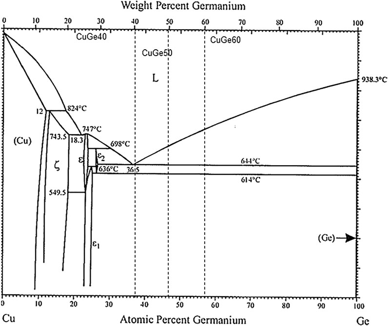
FIGURE 1. Binary phase diagram of Copper and Germanium (Okamoto, 2010).
The eutectic mixture corresponded to the CuGe40 =
From the viewpoint of volume change during phase change, a hypereutectic Cu–Ge alloy contains more Ge compared to that of the eutectic composition, thereby indicating that the volume change of the PCM can be controlled at the phase change (solid/liquid phase). The possibility of volume change by varying the chemical composition of the Cu–Ge alloy was also investigated in this study.
Preparation
The Cu–Ge alloys were synthesized from reagents (high-purity materials, KOJUNDO CHEMICAL LABORATORY CO, LTD.) in a laboratory. A fine powder of copper (purity 99.9%, 180 µm) and germanium (4N, 300 µm) were weighed and mixed in an alumina boat. The alumina boat containing the powders was heated at 1,400°C for 2 h in an Ar stream of 1 dm3/min at a normal state to prevent oxidation during the alloying process, and to melt the powder and form ingots of Cu–Ge alloy. The ingots of Cu–Ge alloy were subjected to homogeneous heat treatment at 800–900°C under vacuum. The ingot was cut into pellets (diameter <25 mm and thickness <10 mm) and chemically washed and cleaned to remove oil and dust from the surface. The identification of the solid phase and structural characterization of the Cu–Ge alloy were carried out by X-ray diffraction (XRD) (D2Phaser, Burker) using CuKα radiation (λ = 0.15418 nm) (30 kV-10 mA) at room temperature. The specimens for XRD measurement were prepared by utilizing a mounting press on phenolic resin to encapsulate the alloy and adding a layer of carbon conductive filler. The surface of the alloy was polished using SiC paper and then mounted on a specimen holder ring. Diffraction data were collected in the angular range corresponding to 10° < 2θ < 80° with a 0.02° step size and a 1-s step interval. The crystalline phases were identified by comparison with standard reference patterns (Inorganic Crystal Structure Database, ICSD) (ICSD, 2020) and the Crystallography Open Database (COD). The lattice cell parameters of the refined structures of the synthesized solid phase were evaluated via Rietveld refinement of the structure models by using the pattern fitting method of the FullProf package.
Thermo-Physical Properties at High Temperatures
There is a paucity of studies on the values of the specific heat (Cp) based on the temperature and thermophysical properties of the Cu–Ge alloy. The phase transition temperatures and enthalpy of fusion for Cu–Ge alloys with a wide range of chemical compositions have been examined (Zhai et al., 2012). In this study, the melting, solidification, and eutectic temperatures, enthalpies, and specific heat capacity of the alloys were measured using differential scanning calorimetry [DSC, NETZSCH DSC 404 F3 Pegasus® manufactured by NETZSCH Co. Ltd., temperature resolution of ±0.0025 × |t| °C)] under an Ar flow of 100 ml/min with a heating and cooling rate of 10°C/min between room temperature and 900°C. Heating/cooling cycles in DSC were repeated three times under an Ar stream. From these measurements, the temperature dependence of sensible heat was estimated using the measured Cp values of the Cu–Ge alloy via DSC.
The thermal volume change of the Cu–Ge alloys was measured via thermomechanical analysis (TMA, NETZSCH 4000 SE, temperature resolution of ±0.5°C). To measure the thermal expansion/shrinkage when the phase changes between solid and liquid phases at high temperature, we designed and customized a sample holder to put the sample in the TMA equipment. The sample holder comprised a hollow cylinder (inner diameter of 6.5 mm, outer diameter, 10.5 mm, length, 22 mm) and pistons (diameter, 6.4 mm, length, 8 mm). A test sample of the Cu–Ge alloy (diameter, 6.2 mm, length, 7.5 mm) was prepared in a laboratory. The test sample was placed in the customized sample holder (inner diameter of 6.5 mm, length, 22 mm), and the test unit was placed in the TMA equipment. The coefficient of thermal expansion/shrinkage based on the temperatures and phase change between solid and liquid phases at specific temperatures was monitored under an N2 flow of 100 ml/min with a heating and cooling rate of 5°C/min. The density of the Cu–Ge alloys was measured at 25°C using the Archimedes method. The temperature dependence of the density of the Cu–Ge alloys was determined using TMA data.
Thermal diffusivity of the Cu–Ge alloys was measured using a NETZSCH LFA-467HT hyper flash analyzer. The test sample (diameter of 10 mm and thickness of 1.14 mm) was prepared in a laboratory. The test sample was placed in a sapphire container, and the test unit was placed in the LFA equipment. Thermal diffusivity measurements were performed with Xe flashlight (pulse width 600 μs, five shots) at 250 V in an Ar stream at 20–900°C to avoid oxidation of the test sample. The thermal conductivities of the Cu–Ge alloys were calculated using these data.
Thermal Response Tests of Cyclic Charge/Discharge Modes
The thermal response of the charge/discharge modes was tested for the eutectic Cu–Ge alloy (60 wt% Cu-40 wt%Ge) as follows: The experimental arrangement for the thermal response tests is shown in Figure 2. A stainless-steel (SUS310S) test container (length, 200 mm; inner and outer diameters, 93.6 and 101.6 mm, respectively), was used for the thermal charge/discharge performance tests. The PCM container (length, 35 mm; inner diameter, 30 mm, and thickness, 10 mm) was composed of graphitic carbon in vacuum, and stainless steel (SUS 310S) in an air-flow atmosphere and was placed inside the test container. The Cu–Ge alloy was packed into a PCM container. 60 g of the eutectic Cu–Ge alloy was loaded into the PCM container (Figure 2B). For the charge mode, the electric heater was controlled at a constant heating rate of 4–6°C/min (1-9 cycles) and 8–12°C/min (10–20 cycles), to a temperature of 850°C, exceeding the eutectic temperature, based on the chemical composition of the Cu–Ge alloy. The temperature variation of the test container with an endothermic phase change was measured under a controlled heating rate. The temperature was maintained for 60 min to homogenize the melt alloy. Subsequently, the test container was subjected to the discharge mode. For discharge, the electric heater was controlled at different cooling rates, ranging within 4–6°C/min (1–9 cycles) and 4–10°C/min (10–20 cycles), to a temperature of 250°C. Temperature variation of the test container with an exothermic phase change was measured under a controlled cooling rate. The charge and discharge modes for the Cu–Ge alloy were repeated in a vacuum and air atmosphere to evaluate the temperature conformity and repeatability of the phase diagram and the effects on the reproducibility of both modes under different atmospheres and heating/cooling rates. The thermal responses were evaluated during heating and cooling (dT/dt vs. time). The PCM temperature was measured relative to time using a type K thermocouple (temperature resolution of ±0.0075 × |t| °C), which was directly inserted into the crucible inside the test container.
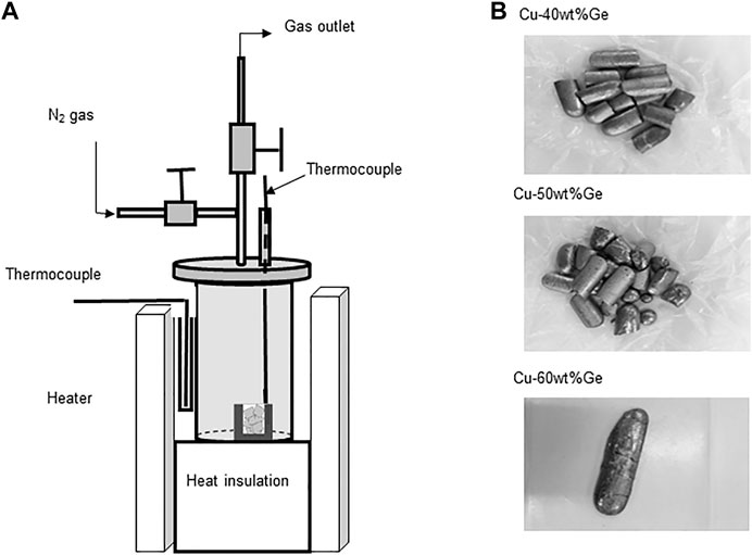
FIGURE 2. Experimental set-up for the thermal response tests of cyclic charge/discharge modes: (A) test vessel and PCM container and (B) Cu–Ge alloy PCMs.
After the thermal response tests, the oxidation state, metallographic structure, and extent of elemental distribution of the Cu–Ge alloy were observed and evaluated. Each element in the Cu–Ge alloy was analyzed using an electron probe microanalyzer (EPMA, Shimadzu EPMA-1610) equipped with a wavelength dispersive X-ray spectrometer (WDS, relative error of <1%) operating at an acceleration voltage of 15 kV, beam current of 200 mA, beam size of 1 μm, step size of 0.5 μm, and sampling time of 0.1 s. The samples for the microstructural analyses were prepared via mechanical grinding and polishing using resin bonded diamond grinding discs (Struers, MD-Piano 1,200, 2,000, and 4,000) to obtain a mirror-like finish prior to EPMA analysis. The chemical compositions of the oxidized outer layer and non-oxidized inner layer were quantitatively measured using EPMA analysis. The average chemical compositions of the oxidized and non-oxidized layers were estimated to evaluate the variation in chemical composition via oxidation.
Chemical Compatibility Test Between the Cu–Ge Alloy and Candidate Materials of Phase Change Materials Container
A chemical compatibility test between the Cu–Ge alloy and candidate materials of the PCM container at high temperature was performed. Stainless steel (SUS 310S, rod-shape), alumina (tube-shape), Inconel625 (rod-shape) and silicon carbide (SiC, powder) were selected as candidate materials. A piece of the Cu–Ge alloy (10 g) was placed together with a PCM container candidate material into a round-bottom-shaped tanman tube (alumina 99.99%, inner diameter of 8 mm and length 25 mm) and heated in vacuum at 800°C for 2 h to pre-melt the Cu–Ge alloy in contact with the candidate materials. A test vessel (length, 120 mm; height, 60 mm) made of stainless steel was used to hold the tanman tube. The tanman tubes were vertically arranged in a test vessel (length, 120 mm; height, 60 mm) within a glovebox maintained in an Ar atmosphere to avoid oxygen contamination, which was then bolted and sealed using an elastic airtight packing (O-ring) made from copper. The test vessel was heated for 720 h at 800°C in a muffle furnace. After the heat treatment, the tanman tubes were removed from the test vessel and cut parallel to the horizontal axis. A piece of test sample was embedded in epoxy resin to observe and evaluate the cross section of the alloy and candidate material of the PCM container. To evaluate the chemical compatibility and the extent of element distribution of the alloy, each of the constituent elements contained in the alloy and the candidate materials were analyzed using an electron probe microanalyzer (EPMA, Shimadzu EPMA-1610) equipped with a wavelength dispersive X-ray spectrometer operating at an acceleration voltage of 15 kV, a beam current of 200 mA, beam size of 2 μm, step size of 2 μm, and sampling time of 30 ms. The samples for the EPMA analysis were mechanically ground and polished using resin bonded diamond grinding discs (Struers, MD-Piano 1,200, 2,000, and 4,000) to obtain a mirror-like finish before EPMA analysis.
Results and Discussion
X-Ray Diffraction Analysis of Synthesized Cu–Ge Alloy
Figure 3 shows XRD patterns of the synthesized CuGe40, CuGe50, and CuGe60 alloys at room temperature in the 2θ range. Blue vertical bars below the XRD pattern indicate the peak positions of the Cu–Ge alloys. The peak positions were compared with XRD data of some phases obtained from the ICSD and COD standard databases, and the phases were identified. A series of peaks, denoted by green vertical bars below the XRD patterns, correspond to the Cu3Ge phase (ICSD-86007). The Cu3Ge phase was equivalent to
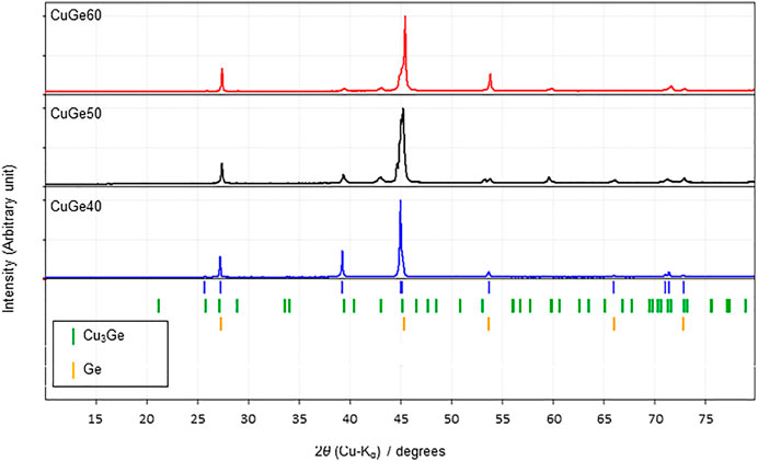
FIGURE 3. XRD patterns of synthesized CuGe40, CuGe50, and CuGe60 alloys.
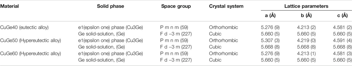
TABLE 1. Solid phases, space grope, crystal system, and lattice parameters of refined structured of Cu–Ge alloys.
Thermo-Physical Properties of Cu–Ge Alloy at High Temperatures
The temperature dependence of specific heat capacities, Cp, and thermal expansion/contraction fraction,
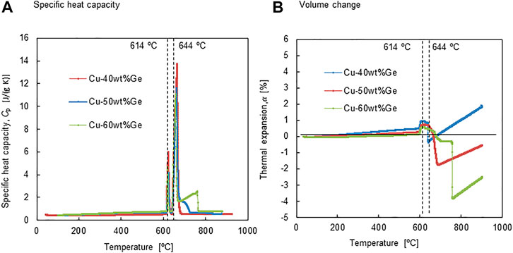
FIGURE 4. (A) specific heat capacity and (B) volume change as a function of temperature for all the alloys.
CuGe40 alloy:
Solid phase
Liquid phase
CuGe50 alloy:
Solid phase
Liquid phase
CuGe60 alloy:
Solid phase
Liquid phase
where Cp has units J/(g°C), and T is in °C. The results shown in Figure 4 were the third dataset, when the experiments were repeated three times. The standard deviations were as follows:
Figure 4B shows the temperature dependence of the linear thermal expansion/contraction
Figure 5A shows the temperature dependence of the apparent density of the CuGe alloys. The apparent density was calculated using the third dataset of thermal expansion/contraction. The apparent density of all alloys at 25°C was measured using Archimedes’ principle and estimated from the volume change data at various temperatures (Figure 4B). The apparent density of CuGe40 was in the range
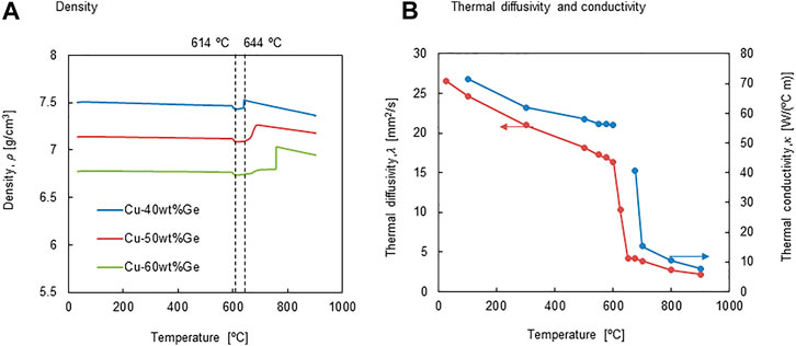
FIGURE 5. (A) density and (B) thermal diffusivity and conductivity as a function of temperature.
In theory, the density of liquid metal at high temperatures can be described by a linear equation, as demonstrated by Cailletet and Mathias (Cailletet and Mathias, 1886). Thus, the measured density data were fitted to the following linear equations:
CuGe40 alloy:
CuGe50 alloy:
CuGe60 alloy:
where temperature T is in °C.
Figure 5B shows the temperature dependence of thermal diffusivity, λ and conductivity
The temperature dependence of the calculated thermal conductivity is shown in Figure 5B. The thermal conductivity at a low-temperature (T < 100°C) for the solid phase of CuGe40 was higher than that for pure germanium (59.9 W/(°C m) @27°C) (AIST, 2019) and much lower than that of pure copper (386 W/(°C m) @ 27°C) (AIST, 2019) and comparable to that at high temperatures (500–600 °C). A main reason for this is the coexistence of the
The following equations give the fitted second-order polynomial for these properties in the liquid phase:
Thermal Storage Performance
Third-generation (Gen3) CSP technology has a new target for the temperatures of HTF (T > 700°C) to ensure higher energy efficiency using supercritical CO2 thermal cycles. Chloride eutectic molten salts are suitable for meeting some important thermophysical properties, including: 1) a melting point that is as low as possible; 2) a boiling point at least 800°C or above; 3) thermophysical properties that are acceptable for convective heat transfer and thermal storage; 4) low corrosion to metal pipes and containers at high temperatures; and 5) low cost. The University of Arizona selected and tested binary eutectic KCl/MgCl2 molten salt that can be used as HTF and sensible thermal storage for next-generation CSP plants (Xu et al., 2018). Researchers at the National Renewable Energy Laboratory (NREL) of the United States reported a new ternary eutectic chloride salt comprising MgCl2-KCl-NaCl as a third third-generation high-temperature HTF and TES in the community of Gen3-CSP (Zhao and Vidal, 2020). In the present study, thermophysical properties of binary and ternary chloride molten salts were compared to the Cu–Ge alloys on the basis of assumption that the molten salts was used as PCMs.
The latent heat storage capacities and dependence of the specific heat, Cp, in the range 100–800°C were measured for all alloys, and the sensible heat was estimated to evaluate the thermal storage performance (Figure 4A). Figure 6 shows (a) heat storage density per unit weight and (b) thermal storage capacity per unit volume for the Cu–Ge alloys. The measured Cp for the solid and liquid phases were utilized to estimate the sensible heat capacities of the solid and liquid phases, respectively. The sensible heat capacity of the solid phase increased with temperature in the range 100–614°C (Figure 6A). In addition, the slope increased with increasing Ge content in the Cu–Ge alloys. The average specific heat capacity of Cu [0.386 J/(g °C)] is higher than that of Ge [0.310 J/(g °C)] in the temperature range 0–100°C (Kinzoku data book, 2018). Thus, these results indicate that the specific heat capacity of Ge has a relatively strong sensitivity at high temperatures. Small discontinuous changes are the sum of sensible heat and latent heat released/stored in the solid/solid phase transition (
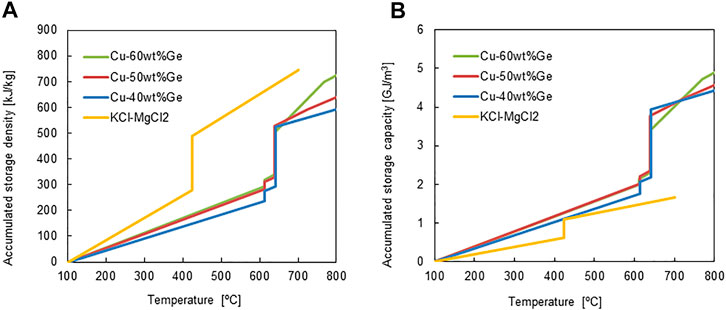
FIGURE 6. (A) accumulated thermal storage density and (B) accumulated thermal storage capacity for all the alloys and chloride molten salt.
The thermophysical properties of the Cu–Ge alloys were compared with those of the binary chloride molten salt (Table 2). The heat storage densities per unit weight for the Cu–Ge alloys were compared to those of the binary chloride molten salt (Xu et al., 2018), and are plotted in Figure 6B. For the ternary molten salt, the values of Cp in the solid state have not been previously reported (Zhao, 2020); thus, the data were not plotted. The accumulated storage density at 700°C was greater for the chloride molten salt than for all alloys (Figure 6A). In addition, the liquid phase of the molten salt has a larger storage capacity compared to all alloys. It is very promising as an HTF and liquid TES in next-generation CSP technologies. However, the accumulated sensible heat capacities of solid phase for all alloys was higher than that of the chloride molten salts (Figure 6B) due to the high density of the alloys (molten salt of 1.89 g/cm3 (extrapolation value at 25°C); Cu–Ge alloys of 6.77–7.50 g/cm3 (25°C). The latent heat capacities of all alloys at the eutectic temperature were also superior to those of chloride molten salts. In addition, all alloys exhibited a high thermal conductivity in the solid/liquid phases and little density change at the solid/liquid transition. These results indicate the potential of all alloys as PCMs, based on the limitations of the usable volume in an LTES system. In the ongoing Gen3 liquid pathway project, two options are considered suitable for reaching high temperatures: 1) direct heating of a chloride molten salt; and 2) indirect heating via liquid sodium and an associated sodium‒salt heat exchanger (Energy Efficiency and Renewable Energy, 2021). Both options use a two-tank system comprising a hot tank and cold tank for chloride molten salt storage. To reduce the storage cost of constituent materials for large quantities of thermal energy storage, 1-tank thermocline system, which is a storage mixture of low-cost sensible material (for example, rock) and latent PCM filler (for example, capsulated alloy), may be a promising technology in view of the limitations of the useable volume for TES. The volumetric capacity of heat storage is a key parameter for next-generation CSP technologies.
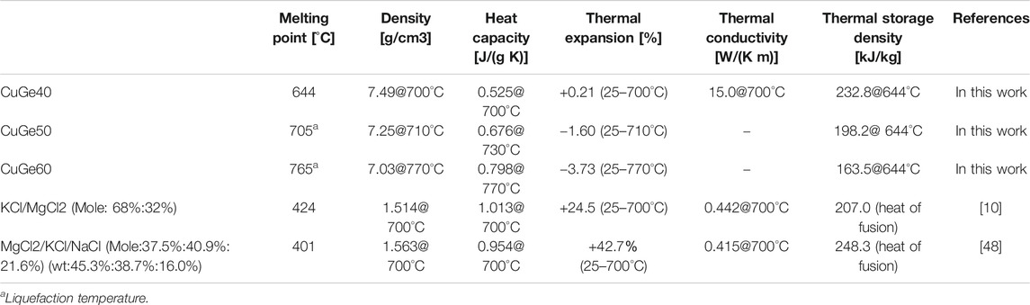
TABLE 2. Comparison of thermophysical properties for CuGe alloys and molten salts in a liquid phase.
Thermal Response Tests of Cyclic Charge/Discharge Modes
When the alloys are installed as latent heat storage (PCM) into the TES of a CSP plant, the alloy is subjected to numerous day–night cycles, and the evaluation of repeatability and compatibility is necessary. In the present study, short-term reliability (repeatability of the charge/discharge performance and compatibility with the PCM container) was initially evaluated via 20 cycle tests using a few dozen Gram samples (Figure 7). From a thermodynamic viewpoint, CuGe40 must behave reproducibly based on the phase diagram (Figure 1) during the thermal response test if it does not chemically react with the container and stream gas. From a kinetics viewpoint, for the phase transition between solid and liquid phases, it is desirable that charge/discharge responds quickly at the eutectic temperature assigned in the phase diagram.
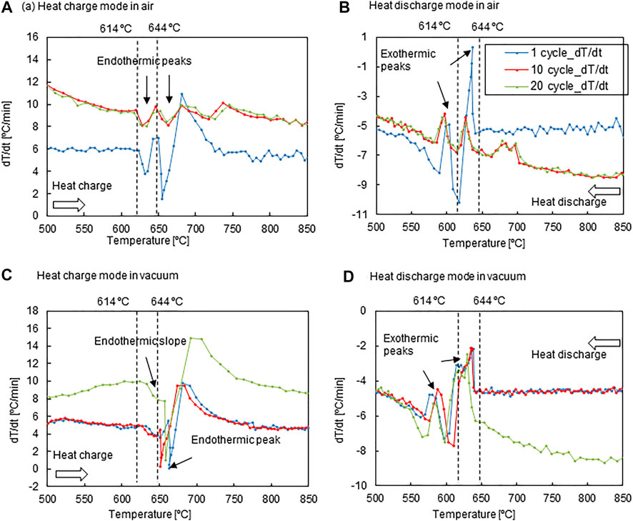
FIGURE 7. dT/dt variations of the PCM temperature for the CuGe40 alloy in an air stream during the (A) heat-charge mode and (B) dis-charge mode, and in a vacuum during the (C) heat-charge mode and (D) heat-discharge mode.
Figure 7 shows dT/dt vs. the PCM temperature T for the CuGe40 in an air stream and a vacuum. The thermal response is influenced by heating/cooling rates, heat transfer, gas stream in the PCM container, and container material. Thus, the main purpose is to examine thermal response and repeatability of the CuGe40 placed in a crucible in an air stream. The crucible was made of SUS304 stainless steel with excellent thermal conductivity and oxygen resistance. To examine the impact of oxygen in the gas stream on the charge/discharge performance, the test was performed using ambient air. In addition, tests in vacuum were conducted to compare the impact of thermal conduction and radiation without convective heat transfer from the external heater into the PCM. Strong endothermic peaks for all cycles were observed immediately after, at temperatures of 614 and 644°C during the heat charge mode (Figure 7A). The peak temperatures were in agreement with the
During heat discharge, a strong peak consistently appeared at 644°C, and a strong peak appeared at 614°C (Figure 7B). The exothermic behaviors for all cycles corresponded to the solidification of the eutectic mixture from the melting alloy and the solid/solid phase transition (
Figure 7C shows the dT/dt profiles plotted relative to the PCM temperature measured under vacuum. The cyclic thermal response was examined using a PCM container composed of graphitic carbon. Additionally, heat charging was imposed at heating rates of 5–6°C/min for the first ten cycles, but at 8–10°C/min for the remaining ten cycles. The thermal response of the CuGe40 alloy in a vacuum is governed by thermal conduction and radiation from the heater into the alloy. An endothermic very weak peak due to solid/solid phase transition for all cycles was observed at an onset temperature of 633°C (Figure 7C), and the peak temperature was shifted to a higher temperature when in an air stream (Figure 7A). Similarly, a strong endothermic peak, due to the melting of the eutectic mixture, was observed at temperatures of 651–663°C. This is because of deficient and inhomogeneous heat transfer without convection in a vacuum. The endothermic behavior in the dT/dt profiles was almost the same for different heating rates. The repeatability of charge performance under vacuum during the 2nd-20th cycles was inferior to in the air stream.
During heat-discharge (Figure 7D), the cooling rate was set to 4–5°C/min for the initial ten cycles and dynamically changed between 6 and 9°C/min for the remaining ten cycles. A very strong exothermic peak, due to the solidification of the eutectic mixture from the melting alloy, was observed for all cycles, with an onset temperature of 644°C. However, an exothermic peak due to the solid-state phase transition appeared at an onset temperature of 610–598°C. The reason for this fluctuation is the cooling process in vacuum, which is governed by the limited heat transfer. Thus, the heat stored in the alloy was not quickly released into the atmosphere. This leads to a delay and fluctuation (poor repeatability) in the onset temperature of the exothermic process. The impact on the cooling rate was not clearly observed during discharge under vacuum. The thermal response of the exothermic peaks was consistently observed under fluctuating onset and termination temperatures for the solid-state phase transition and solidification of the eutectic mixture for all cycles. The CuGe alloy behaved consistently, based on the thermodynamic equilibrium in a gas stream and quickly responded under the limited heat transfer without the effect of alloy oxidation in vacuum.
To evaluate the effect of oxidation during the thermal response test in an air stream, and chemical compatibility between the stainless steel vessel and CuGe50 alloy (sample), the microscopic distribution of the sample and vessel elements was examined after the test. Figure 8 shows the backscattered electron image (BEI) micrograph of the cross-sectional surface of the sample and elemental mapping images of Ge, Cu, Fe, O, Ni, and Cr. These analytical elements were selected from the main constituents of the sample and the vessel. The BEI image consists of a light gray area (right side of the image), a dark gray area (upper-left side of the image), and a black area (lower left side of the image). The black area corresponds to the epoxy resin used to mount the sample. The light gray area represents the internal microstructure of the alloy without oxidation, while the dark gray area is an oxidation layer in which the alloy was externally covered. The BEI image indicates that an oxidation layer was formed on the surface of the alloy during the heat charge-discharge process in air. In the mapping images of the Ge element, the green region is widely spread in the oxidation layer (dark gray area) in the BEI image. In addition, a number of red, yellow and green microscopic spots and needles (Ge solid solution, aggregation of coarsened particles) and a blue region (mainly the
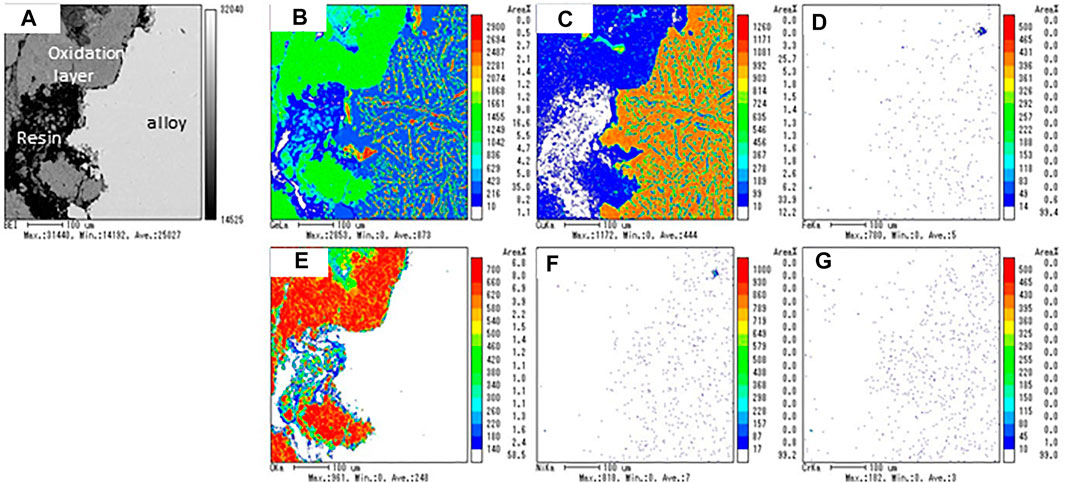
FIGURE 8. (A) Backscattered electron image (BEI) micrograph and elemental mapping images of (B) Ge, (C) Cu, (D) Fe, (E) O, (F) Ni, and (G) Cr for the sample obtained after the thermal response test in an air stream.
The blue region of the Ge mapping image corresponds to the brown region of Cu mapping. A number of reddish-brown spots and yellowish-brown areas surrounding the reddish-brown spots appeared in the Cu mapping. Because the reddish spots have a relatively higher Cu content than the yellowish area, the authors consider that the brown region of the Cu mapping is composed of two phases: the reddish spots correspond to the thermodynamically stable
As seen in the O mapping image, the internal microstructure of the alloy was observed with no oxidation; the formation of the oxidation layer was observed in the dark gray area of the BEI image. The thickness of the oxidation layer was in the range of 100–200 mm (Figure 8A). The chemical composition of the alloy and oxidation layers were quantified by randomly selecting five points by EPMA analysis (Table 3). The average weight ratio of Ge65.1Cu5.4O29.5 for the oxidation layer corresponded to a solid mixture of GeO2/CuO (or Cu2O) = 10/1, and that of Cu64Ge36 for the alloy corresponded to a solid mixture of hypoeutectic chemical composition (67 at%Cu-33 at%Ge). These results indicate that Ge was preferentially oxidized compared to Cu in the CuGe50 alloy, resulting in compositional deviation of the alloy. The chemical composition and thickness of the oxidation layer may impact on charge/discharge storage performance and thermal response. The thermal response of the PCM lowered by the formation of the oxidation layer as far as appears in Figures 7A,B. In order to quantitatively estimate the impacts on storage performance under the oxidation layer, a numerical simulation of the PCM covered the oxidation layer and comparison with the experiments are required in some future works.
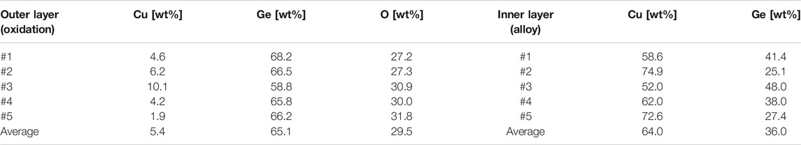
TABLE 3. EPMA analysis of chemical composition for the oxidized outer layer and the internal microstructure of the alloy.
As seen in the mapping images (Figure 8) of the Fe, Ni, and Cr elements, the internal region of the alloy and the oxidation layer did not chemically react with the stainless steel container under the test conditions. These results indicate that the container (SUS310S) can be used as a PCM container in an air stream during charge-discharge modes.
Chemical Compatibility Test at High-Temperate
To use the alloy as a PCM in a thermal storage system, the alloy should be encapsulated by a material having an excellent thermal conductivity, high-temperature resistance, and corrosion resistance at high temperatures. Consequently, the chemical compatibility between the alloys and candidate container materials was tested at high temperatures. The chemical compatibility between the alloys (CuGe40, CuGe50, and CuGe60) and the candidate materials (stainless steel (SUS 310S), alumina, Inconel625, and silicon carbide (SiC)) was examined and evaluated by cross-reactivity at high temperature using EPMA analysis. Figure 9 shows the results of the EPMA analysis for a combination of SUS 310S/CuGe50. A light gray area of Cu-rich and Ge-poor contents, and dark gray areas of Ge, Fe, Ni, and Cr-rich contents, were observed in the backscattered electron image (BEI) micrograph (Figure 9A). In addition, the high Ni content region was locally distributed in the Cu-rich alloy. A black region observed on the left side of the image corresponded to the epoxy resin used to mount the sample. No oxidation of either area appeared in the mapping image of the O element (Figure 9G), which supports the compatibility test without the oxidation effect. These results show that corrosion of the stainless steel into the CuGe50 alloy occurred at high temperatures and SUS310S stainless steel was not chemically compatible with the studied alloy.
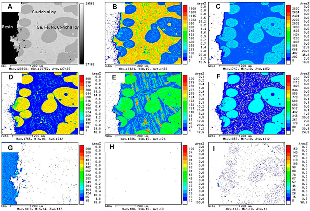
FIGURE 9. The results of the EPMA analysis for the chemical compatibility test of SUS 310S/CuGe50. (A) BEI image, (B) Cu, (C) Ge, (D) Fe, (E) Ni, (F) Cr, (G) O, (H) Al, and (I) Si mapping images.
Figure 10 shows the results of EPMA analyses for a combination of Inconel625/CuGe40. A vertical array of voids appeared at the center of the BEI image (Figure 10A). This was due to the initial bonded interface of Inconel625/CuGe40, or Kirkendall voids, which generally are an accumulation of atomic vacancies generated by the imbalance in the interdiffusion on the bonded interface. The observation area of the BET image was classified as deep dark gray of Ni-rich content, dark gray area of Cu-rich and Ge-poor contents, and light gray areas of Cr, Ge, and Mo-rich contents. These results show that the Cu and Ge atoms of the alloy diffused into the Inconel layer, and Ni atoms diffused into the CuGe alloy at high-temperatures. Thus, Inconel625 is chemically bonded with the CuGe40 alloy during the test, which is not chemically compatible with the combination at high-temperatures.
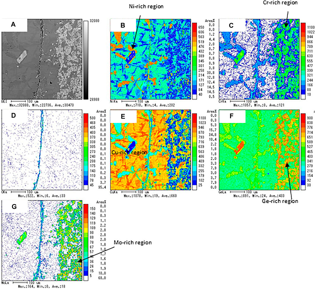
FIGURE 10. The results of the EPMA analysis for the chemical compatibility test of Inconel625/CuGe40. (A) BEI image, (B) Ni, (C) Cr, (D) O, (E) Cu, (F) Ge, and (G) Mo mapping images.
Figure 11 shows the results of the EPMA analyses for a combination of alumina/CuGe60/SUS 310S, that is, the chemical compatibility between the tanman-tube crucible made from alumina (purity of 99.99%) and CuGe60/SUS 310S. No dissolution of Al and O from alumina was found in the Cu-rich and Ge, Fe, Ni, and Cr-rich alloys. These results demonstrated that alumina is fully compatible with CuGe60 alloy in a closed inert atmosphere at high temperatures. Figure 12 shows the results of the EPMA analysis for a combination of CuGe50/SiC heated in a tanman-tube crucible. The BEI image demonstrates an interface, where the SiC powder is on the left side and CuGe50 alloy is on the right is clearly observed in the cross-section of the surface of the CuGe alloy and SiC. In addition, Si and C were distributed on the left side without interdiffusion, while Cu and Ge were distributed on the right, without spreading on the other side. After the test, the combined material was easily removed from the tanman crucible. Therefore, no chemical corrosion occurred for the combination of CuGe50/SiC. These results demonstrated that SiC has good compatibility with the chosen alloy and crucible under an inert atmosphere.
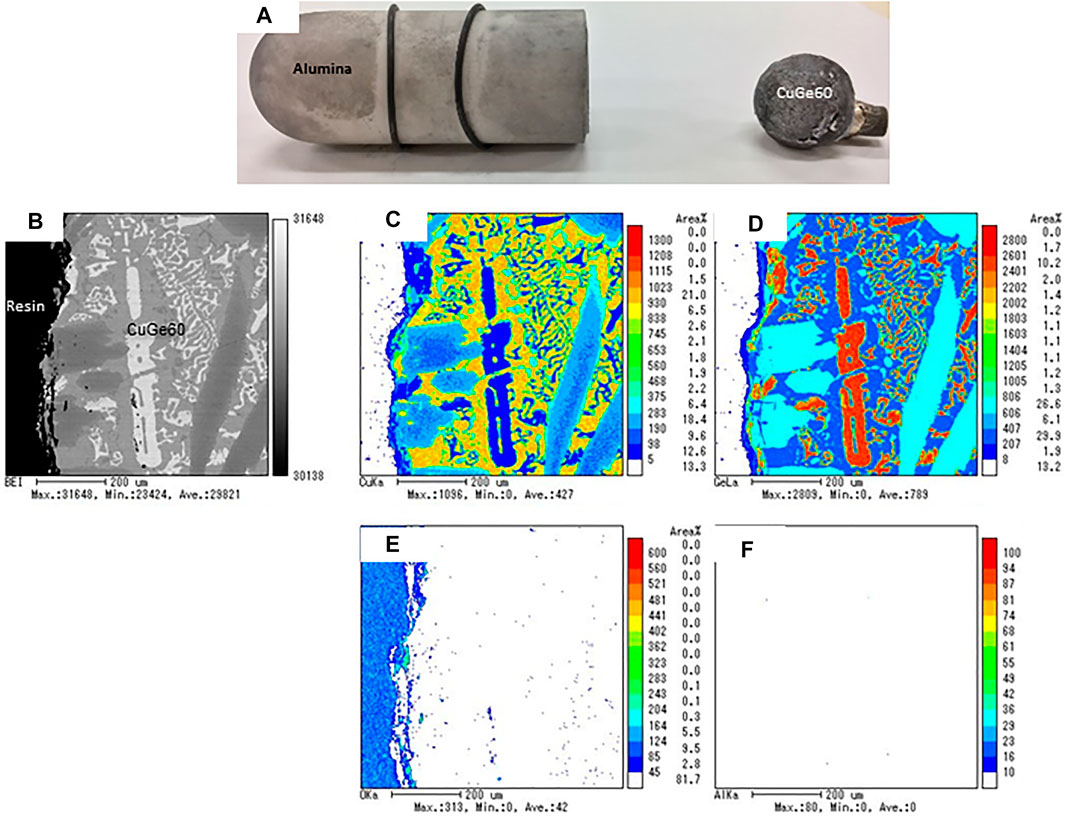
FIGURE 11. The results of the EPMA analysis for the chemical compatibility test of alumina/CuGe60. (A) photograph of alumina tube and test sample, (B) BEI image, (C) Cu, (D) Ge, (E) O, and (F) Al mapping images.
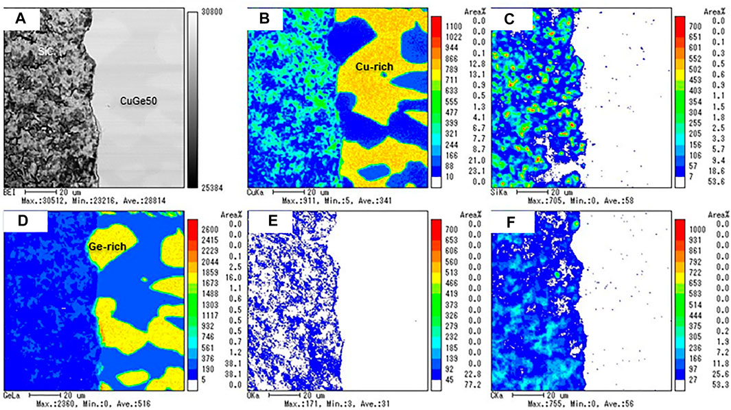
FIGURE 12. The results of the EPMA analysis for the chemical compatibility test of CuGe50/SiC. (A) BEI image, (B) Cu, (C) Si, (D) Ge, (E) O, and (F) C mapping images.
Summary
Eutectic and hypereutectic Cu–Ge alloys were studied as promising metallic PCMs, with liquefaction temperatures to 800°C, for next-generation CSP applications at temperatures exceeding 600°C. The thermophysical properties of the Cu–Ge alloy, including the melting temperature, specific heat capacity, volume change, density, thermal diffusivity/conductivity, and latent heat were examined to evaluate the potential of the Cu–Ge alloy as a metallic PCM for TES. Furthermore, the thermal response and consistency of the thermal charge/discharge of the Cu–Ge alloy were studied and compared to the phase diagram, based on thermodynamic equilibrium. Finally, chemical compatibility between the Cu and Ge alloy and candidate materials of the PCM container was tested and evaluated to identify potential construction materials for PCM container/encapsulation.
The specific heat capacities of all the alloys have not previously been reported. The specific heat capacity as a function of temperature was successfully formulated for solid and liquid states, and the measured values for both phases were utilized to estimate the sensible heat of the solid and liquid phases. The temperature dependence of the volume change was measured for all alloys. The volume of the alloys increased owing to the solid phase transition from the
The latent heat storage densities, capacities, and sensible heat were estimated to evaluate the thermal storage performance in the temperature range 100–800°C. The sensible heat of the solid phase increased with temperature in the range 100–614°C. In addition, the slope increased with increased Ge content in the Cu–Ge alloys. Thus, these results indicate that the specific heat capacity of Ge has a relatively strong sensitivity at high temperatures. Small discontinuous changes corresponded to the latent heat released/stored in solid/solid phase transition (
The short-term reliability (repeatability of the charge/discharge performance and compatibility with the PCM container) and thermal response of CuGe40 were evaluated via 20 cycle tests in an air stream and vacuum. Strong endothermic/exothermic peaks for all cycles were observed immediately after, at 614 and 644°C during the heat charge/discharge modes in the air stream. The peak temperatures were in good agreement with the
The chemical compatibility between the CuGe alloys (CuGe40, CuGe50, and CuGe60) and candidate container materials (stainless steel (SUS 310S), alumina, Inconel625, and silicon carbide (SiC)) was tested at high temperatures and evaluated by EPMA analysis. For SUS 310S and Inconel625, corrosion and chemically bonded with the CuGe alloys at high temperatures was observed. Thus, there materials were not chemically compatible with the studied alloy. However, For a combination of SUS 310S/CuGe50, corrosion of the stainless steel into the CuGe50 alloy at high temperatures was observed and the SUS310S stainless steel was not chemically compatible with the studied alloy. For a combination of Inconel625/CuGe40, Cu. and Ge atoms of the alloy diffused into the Inconel layer, and Ni atoms diffused into the CuGe alloy at high temperatures. Thus, Inconel625 was chemically bonded with the CuGe40 alloy during the test and therefore this combination was not chemically compatible at high temperatures. For a combination of alumina/CuGe60/SUS 310S, no dissolution of Al and O from alumina was found in any area of the alloy. Alumina was therefore fully compatible with the CuGe60 alloy in a closed inert atmosphere at high temperatures. Finally, for a combination of CuGe50/SiC heated in the tanman-tube crucible, the sample was easily removed from the tanman crucible after the test. Therefore, no chemical corrosion occurred for the combination of CuGe50/SiC. The results demonstrate that SiC has good compatibility with the chosen alloy and crucible under an inert atmosphere.
Some merits of CuGe alloy relative to chloride molten salt in CSP technologies are 1) quick thermal response due to superior thermal conductivity, 2) no corrosive properties at elevated temperatures to alumina and SiC used as an insulated liner/capsulation material in vessels or tanks, 3) very small volume change at solid/liquid phase change leading to high loading amount in the PCM capsule, 4) high thermal-reliability without thermal decomposition. Their properties are suitable to alleviate thermal shocks, solar fluctuations, and radiation transients. However, the demerits of CuGe alloy are 1) low oxidation-resistance at elevated temperatures, 2) low chemical compatibility with stainless steel and Inconel alloys used in vessels or tanks. Based on the experimental results above, eutectic and hypereutectic CuGe alloys are satisfactory and acceptable for use as latent heat storage materials exposed to high temperatures in next-generation CSP plants.
Data Availability Statement
The original contributions presented in the study are included in the article/Supplementary Material, further inquiries can be directed to the corresponding author.
Author Contributions
NG contributed to perform conceptualization, methodology, validation, software, formal analysis, writing–original draft, writing–review and editing, visualization, supervision, project administration, funding acquisition; CSJ, YN, and SO contributed to conduct formal analysis, investigation, visualization; TK contributed to provide software and resource; TH contributed to investigation, and funding acquisition; SB contributed to provide resource.
Funding
This research was partially supported by the Ministry of Education, Culture, Sports, Science and Technology, Grant-in-Aid for Scientific Research (B), JSPS KAKENHI (grant number 19H02658) and Grant-in-Aid for Scientific Research (C), JSPS KAKENHI (grant number 20K05398).
Conflict of Interest
The authors declare that the research was conducted in the absence of any commercial or financial relationships that could be construed as a potential conflict of interest.
Acknowledgments
The authors gratefully acknowledge technical staff (Katsutoshi Iwafune) for supporting the XRD measurement and technical staff (Masayoshi Kobayashi, and Ayako Ikarashi) for supporting the EPMA measurement at Niigata University.
References
Adinberg, R., Zvegilsky, D., and Epstein, M. (2010). Heat Transfer Efficient thermal Energy Storage for Steam Generation. Energ. Convers. Management 51 (1), 9–15. doi:10.1016/j.enconman.2009.08.006
Agüero, A., Audigié, P., and Rodríguez, S. (2019). 10,000 H of Corrosion Testing on Molten Salt of IN617 and Uncoated and Aluminide Coated Ferritic Steels at 580°C. Solar PACES proceedings. Melville, NY: AIP Publishing LLC, 150002. doi:10.1063/5.0028930
Aist, (2019). Thermophysical Properties Database System. Availble at:https://tpds.db.aist.go.jp/ (Accessed March 20, 2021).
Birchenall, C. E., and Riechman, A. F. (1980). Heat Storage in Eutectic Alloys. Mta 11 (8), 1415–1420. doi:10.1007/bf02653497
Blanco-Rodríguez, P., Rodríguez-Aseguinolaza, J., Risue∼no, E., and Tello, M. (2014). Thermophysical Characterization of Mg–51%Zn Eutectic Metal alloy: A Phase Change Material for thermal Energy Storage in Direct Steam Generation Applications. Energy 72 (1), 414–420.
Bonk, A., Braun, M., Hanke, A., Sötz, V. A., and Bauer, T. (2019). Enhancing the thermal Stability of Solar Salt up to 600°C in Extended Lab-Scale Experiments. SolarPACES proceedings. Melville, NY: AIP Publishing LLC.
Cailletet, L., and Mathias, E. (1886). Recherches sur les densités des gaz liquéfiés et de leurs vapeurs saturées. J. Phys. Theor. Appl. 5, 549–564. doi:10.1051/jphystap:018860050054900
Carlson, M., Alvarez, F., and Dorsey, D. (2020). 200 MWth and 1 MWth Chloride Salt to Supercritical Carbon Dioxide Heat Exchanger and Test Integration Designs. SolarPACES proceedings. Melville, NY: AIP Publishing LLC. doi:10.1115/es2020-1675
Cohen, G. (2008). “Nevada Solar One Update,” in Proceedings of the Third Concentrated Solar Power Summit US.
El Karim, Y., Grosu, Y., Faik, A., and Lbibb, R. (2019). Investigation of Magnesium-Copper Eutectic Alloys with High thermal Conductivity as a New PCM for Latent Heat thermal Energy Storage at Intermediate-High Temperature. J. Energ. Storage 26, 100974. doi:10.1016/j.est.2019.100974
Energy Efficiency and Renewable Energy, (2021). Generation 3 Concentrating Solar Power Systems (Gen3 CSP). Washington, DC: Solar Energy Technologies Office, 20585. Available at:https://www.energy.gov/eere/solar/generation-3-concentrating-solar-power-systems-gen3-csp (Accessed March 20, 2021).
Fang, D., Sun, Z., Li, Y., and Cheng, X. (2016). Preparation, Microstructure and thermal Properties of MgBi Alloys as Phase Change Materials for thermal Energy Storage. Appl. Therm. Eng. 92, 187–193. doi:10.1016/j.applthermaleng.2015.09.090
Farkas, D., and Birchenall, C. E. (1985). New Eutectic Alloys and Their Heats of Transformation. Metall. Mat Trans. A. 16, 323–328. doi:10.1007/bf02814330
Fukahori, R., Nomura, T., Zhu, C., Sheng, N., Okinaka, N., and Akiyama, T. (2016). Thermal Analysis of Al-Si Alloys as High-Temperature Phase-Change Material and Their Corrosion Properties with Ceramic Materials. Appl. Energ. 163, 1–8. doi:10.1016/j.apenergy.2015.10.164
Gil, A., Medrano, M., Martorell, I., Lázaro, A., Dolado, P., Zalba, B., et al. (2010). State of the Art on High Temperature thermal Energy Storage for Power Generation. Part 1-Concepts, Materials and Modellization. Renew. Sustainable Energ. Rev. 14, 31–55. doi:10.1016/j.rser.2009.07.035
Gokon, N., Jie, C. S., Nakano, Y., Kodama, T., Bellan, S., and Cho, H. (2020). Thermal Charge/discharge Performance of Iron-Germanium Alloys as Phase Change Materials for Solar Latent Heat Storage at High Temperatures. J. Energ. Storage 30, 101420. doi:10.1016/j.est.2020.101420
Gokon, N., Nakamura, S., Yamaguchi, T., and Kodama, T. (2015). Cyclic Properties of thermal Storage/discharge for Al-Si alloy in Vacuum for Solar Thermochemical Fuel Production. Energ. Proced. 69, 1759–1769. doi:10.1016/j.egypro.2015.03.145
Gokon, N., Yamaguchi, T., and Kodama, T. (2016). Cyclic thermal Storage/discharge Performances of a Hypereutectic Cu-Si alloy under Vacuum for Solar Thermochemical Process. Energy 113, 1099–1108. doi:10.1016/j.energy.2016.07.005
Goswami, D. Y. (2015). Principles of Solar Engineering. 3rd Edn. Boca Raton: CRC Press, 822. doi:10.1201/b18119
ICSD (2020). Inorganic Crystal Structure Database (ICSD). Available at: https://icsd.products.fiz-karlsruhe.de/.
International Energy Agency (IEA) (2020). World Energy Outlook. Available at:https://www.iea.org/reports/world-energy-outlook-2020. (Accessed March 20, 2021).
IRENA (2018). Renewable Power Generation Costs in. Available at: https://www.irena.org/-/media/Files/IRENA/Agency/Publication/2019/May/IRENA_Renewable-Power-Generations-Costs-in-2018.pdf.
IRENA (2016). The Power to Change: Solar and Wind Cost Reduction Potential to 2025. Available at: https://www.irena.org/publications/2016/Jun/The-Power-to-Change-Solar-and-Wind-Cost-Reduction-Potential-to-2025.
Islam, M. T., Huda, N., Abdullah, A. B., and Saidur, R. (2018). A Comprehensive Review of State-Of-The-Art Concentrating Solar Power (CSP) Technologies: Current Status and Research Trends. Renew. Sustain. Energ. Rev. 91, 987–1018. doi:10.1016/j.rser.2018.04.097
Khare, S., Dell’Amico, M., Knight, C., and McGarry, S. (2012). Selection of Materials for High Temperature Latent Heat Energy Storage. Solar Energ. Mater. Solar Cell 107, 20–27. doi:10.1016/j.solmat.2012.07.020
Kinzoku data book (2018). The Japan Institute of Metals and Materials. 4th Edn. Tokyo, Japan: MARUZEN-YUSHODO Company, Limited.
Kotzé, J. P., von Backström, T. W., and Erens, P. J. (2013). High Temperature thermal Energy Storage Utilizing Metallic Phase Change Materials and Metallic Heat Transfer Fluids. J. Sol. Energ. Eng. Tran. ASME 135, 035001. doi:10.1115/1.4023485
Kuravi, S., Trahan, J., Goswami, D. Y., Rahman, M. M., and Stefanakos, E. K. (2013). Thermal Energy Storage Technologies and Systems for Concentrating Solar Power Plants. Prog. Energ. combustion Sci. 39, 285–319. doi:10.1016/j.pecs.2013.02.001
Medrano, M., Gil, A., Martorell, I., Potau, X., and Cabeza, L. F. (2010). State of the Art on High-Temperature thermal Energy Storage for Power Generation. Part 2-Case Studies. Renew. Sustainable Energ. Rev. 14, 56–72. doi:10.1016/j.rser.2009.07.036
Mehos, M., Turchi, C., Vidal, J., Wagner, M., Ma, Z., Ho, C., et al. (2017). Concentrating Solar Power Gen3 Demonstration Roadmap, Nrel/Tp-5500-67464, 140. Available at: https://www.osti.gov/biblio/1338899-concentrating-solar-power-gen3-demonstration-roadmap.
Nomura, T., Zhu, C., Sheng, N., Saito, G., and Akiyama, T. (2015). Microencapsulation of Metal-Based Phase Change Material for High-Temperature Thermal Energy Storage. Sci. Rep. 5, 9117. doi:10.1038/srep09117
Pelay, U., Luo, L., Fan, Y., Stitou, D., and Rood, M. (2017). Thermal Energy Storage Systems for Concentrated Solar Power Plants. Renew. Sustainable Energ. Rev. 79, 82–100. doi:10.1016/j.rser.2017.03.139
Risueño, E., Faik, A., Gil, A., Rodríguez-Aseguinolaza, J., Tello, M., and D'Aguanno, B. (2017). Zinc-rich Eutectic Alloys for High Energy Density Latent Heat Storage Applications. J. Alloys Compounds 705, 714–721. doi:10.1016/j.jallcom.2017.02.173
Rodríguez-Aseguinolaza, J., Blanco-Rodríguez, P., Risueño, E., Tello, M. J., and Doppiu, S. (2014). Thermodynamic Study of the Eutectic Mg49-Zn51 alloy Used for thermal Energy Storage. J. Therm. Anal. Calorim. 117, 93–99. doi:10.1007/s10973-014-3639-0
Skumanich, A. (2010). CSP: Developments in Heat Transfer and Storage Materials. Renew. Energ. Focus 11 (5), 40–43. doi:10.1016/s1755-0084(10)70115-0
Stoffel, T., Renne, D., Myers, D., Wilcox, S., Sengupta, M., George, R., et al. (2010). Concentrating Solar Power- Best Practices Handbook for the Collection and Use of Solar Resource Data (CSP). NREL/TP-550-47465. Golden, CO: National Renewable Energy Lab. (NREL). Available at: https://www.osti.gov/biblio/989017-bvKldG/. doi:10.2172/989017
Sugo, H., Kisi, E., and Cuskelly, D. (2013). Miscibility gap Alloys with Inverse Microstructures and High thermal Conductivity for High Energy Density thermal Storage Applications. Appl. Therm. Eng. 51, 1345–1350. doi:10.1016/j.applthermaleng.2012.11.029
Sun, J. Q., Zhang, R. Y., Liu, Z. P., and Lu, G. H. (2007). Thermal Reliability Test of Al-34%Mg-6%Zn alloy as Latent Heat Storage Material and Corrosion of Metal with Respect to thermal Cycling. Energ. Convers. Management 48 (2), 619–624.
Wang, Z., Wang, H., Li, X., Wang, D., Zhang, Q., Chen, G., et al. (2015). Aluminum and Silicon Based Phase Change Materials for High Capacity thermal Energy Storage. Appl. Therm. Eng. 89, 204–208. doi:10.1016/j.applthermaleng.2015.05.037
Wei, G., Huang, P., Xu, C., Liu, D., Ju, X., Du, X., et al. (2016). Thermophysical Property Measurements and thermal Energy Storage Capacity Analysis of Aluminum Alloys. Solar Energy 137, 66–72. doi:10.1016/j.solener.2016.07.054
Xu, X., Wang, X., Li, P., Li, Y., Hao, Q., Xiao, B., et al. (2018). Experimental Test of Properties of KCl-MgCl2 Eutectic Molten Salt for Heat Transfer and Thermal Storage Fluid in Concentrated Solar Power Systems. J. Solar Energ. Eng. 140, 1051011. doi:10.1115/1.4040065
Zhai, W., Geng, D. L., Wang, W. L., and Wei, B. (2012). A Calorimetric Study of Thermodynamic Properties for Binary Cu-Ge Alloys. J. alloys Compd. 535, 70–77. doi:10.1016/j.jallcom.2012.04.091
Zhang, H., Baeyens, J., Cáceres, G., Degrève, J., and Lv, Y. (2016). Thermal Energy Storage: Recent Developments and Practical Aspects. Prog. Energ. Combustion Sci. 53, 1–40. doi:10.1016/j.pecs.2015.10.003
Zhao, J., Yuan, Y., and Cui, F. (2017). Relationship between the Cu Content and thermal Properties of Al-Cu Alloys for Latent Heat Energy Storage. J. Therm. Anal. Calorim. 129, 109–115. doi:10.1007/s10973-017-6153-3
Zhao, Y. (2020). Molten Chloride Thermophysical Properties, Chemical Optimization, and Purification. Nrel/Tp-5500-78047. Golden, CO: National Renewable Energy Lab. (NREL), 1–82. doi:10.2172/1734652
Keywords: phase change material, thermal storage system, latent heat, copper-germanium alloy, concentrated solar power
Citation: Gokon N, Jie CS, Nakano Y, Okazaki S, Kodama T, Hatamachi T and Bellan S (2021) Phase Change Material of Copper–Germanium Alloy as Solar Latent Heat Storage at High Temperatures. Front. Energy Res. 9:696213. doi: 10.3389/fenrg.2021.696213
Received: 16 April 2021; Accepted: 19 May 2021;
Published: 08 June 2021.
Edited by:
Alfonso J. Carrillo, Instituto de Tecnología Química (ITQ), SpainReviewed by:
María Orfila, Rey Juan Carlos University, SpainRichard Murdey, Kyoto University, Japan
Anastasia Stamatiou, Lucerne University of Applied Sciences and Arts, Switzerland
Copyright © 2021 Gokon, Jie, Nakano, Okazaki, Kodama, Hatamachi and Bellan. This is an open-access article distributed under the terms of the Creative Commons Attribution License (CC BY). The use, distribution or reproduction in other forums is permitted, provided the original author(s) and the copyright owner(s) are credited and that the original publication in this journal is cited, in accordance with accepted academic practice. No use, distribution or reproduction is permitted which does not comply with these terms.
*Correspondence: Nobuyuki Gokon, bmdva29uQGVuZy5uaWlnYXRhLXUuYWMuanA=