 Song Zhang
 Guoqing Li
- Department of Electrical Engineering, Northeast Electric Power University, Jilin, China
Electromechanical transient (EMT) and transient stability hybrid simulations can make full use of their fast-solving ability and high-precision computing ability to accurately simulate the dynamic characteristics of large-scale AC/DC systems. This paper selects the bus as the hybrid simulation interface bus in the AC system near the DC system, which can effectively improve the simulation accuracy of the AC/DC system interaction. At the interface bus, Norton equivalent and Thevenin equivalent are applied to the EMT simulation side and electromechanical transient simulation side, respectively. The three-phase simulation data and three-sequence component simulation data are extracted respectively, and the serial iteration method is used for hybrid simulation calculation. This paper takes Zhangbei multi terminal AC/DC system as an example, compares the hybrid simulation results with the EMT simulation results, and tries to verify the accuracy and effectiveness of the hybrid simulation method.
Introduction
With the proliferation of VSC-HVDC (Voltage Source Converter High Voltage Direct Current) based on power electronic devices, the influence of such fast responding devices on the AC/DC hybrid transmission system has become a research hotspot (Huang and Vittal, 2017a, b; Liming and Bo, 2020; Li et al., 2021). An EMT simulator is widely used in previous research on VSC-HVDC. The simulation results, which are in accordance with the principles of VSC-HVDC, correctly reflect the dynamic characters of the VSC-HVDC system in normal running conditions and fault conditions. However, an EMT simulator is limited in dealing with a bulk AC/DC hybrid transmission system (Venkatraman et al., 2019). This requires researchers and engineers to invest a lot of energy in modeling. Apart from that, the simulation scale is limited by computer resources, which often cannot accurately simulate the behavior characteristics of the whole system. It is necessary to combine the traditional EMT and electromechanical transient simulation methods to complement each other in the hybrid simulation technology, so as to realize the comprehensive analysis and practical engineering application of the large-scale AC/DC system transient process (Schneider et al., 2019).
At present, hybrid simulation technology has widely concerned experts and scholars at home and abroad. Meanwhile, a lot of research work has been done in this field. In reference (Huang and Vittal, 2017b), a hybrid simulation method of transmission and distribution system is established by using a multi region Thevenin equivalent method. Moreover, the dynamic simulation of transmission and distribution network is carried out by using a partition modeling method, which effectively solves the interface hybrid problem of systems with different voltage level. In reference (Plumier et al., 2016), an iterative method of interface data between electromechanical transient simulation and EMT based on a variable vector is proposed, which effectively solves the problem of interface data distortion in hybrid simulation. In reference (Shu et al., 2018), the interface scheme of a hybrid simulation system for an AC/DC system is proposed based on a dynamic vector method, which effectively enhances the stability of the hybrid simulation interface for the AC/DC system. Although the above research focuses on solving the algorithm stability and smoothness of the hybrid simulation interface, there is not much research on the location selection of the hybrid simulation interface.
This paper proves that the dynamic characteristics of the AC/DC system can be accurately simulated by selecting the AC system bus near the DC system as the hybrid simulation interface. The construction method of hybrid simulation system with the AC bus as the interface bus is described in detail, and the serial iteration method is used as the operation flow of the hybrid simulation interface. Taking the Zhangbei multi terminal flexible HVDC transmission system as an example, this paper verifies the accuracy and effectiveness of the proposed hybrid simulation method.
A New Hybrid Simulation Platform Based on Matlab/Simulink and MatDyn
Structure Design of the Hybrid Simulation Platform
The first task of building the hybrid simulation platform is to choose the simulation tools and design the main structure. These foundation works affect not only the applicability of the hybrid simulation but also its scalability. Indeed, a normal decoupled structure for combining an EMT and TS program has been proposed and completed in much of the literature (Zhang et al., 2013). A similar structure is employed in this paper, as shown in Figure 1. The TS and EMT program are under the parallel operation: when one subsystem is simulated, the other is replaced by a Thevenin equivalent system or NORTON equivalent system. The computing method of the equivalent system is introduced in detail in the following chapters.
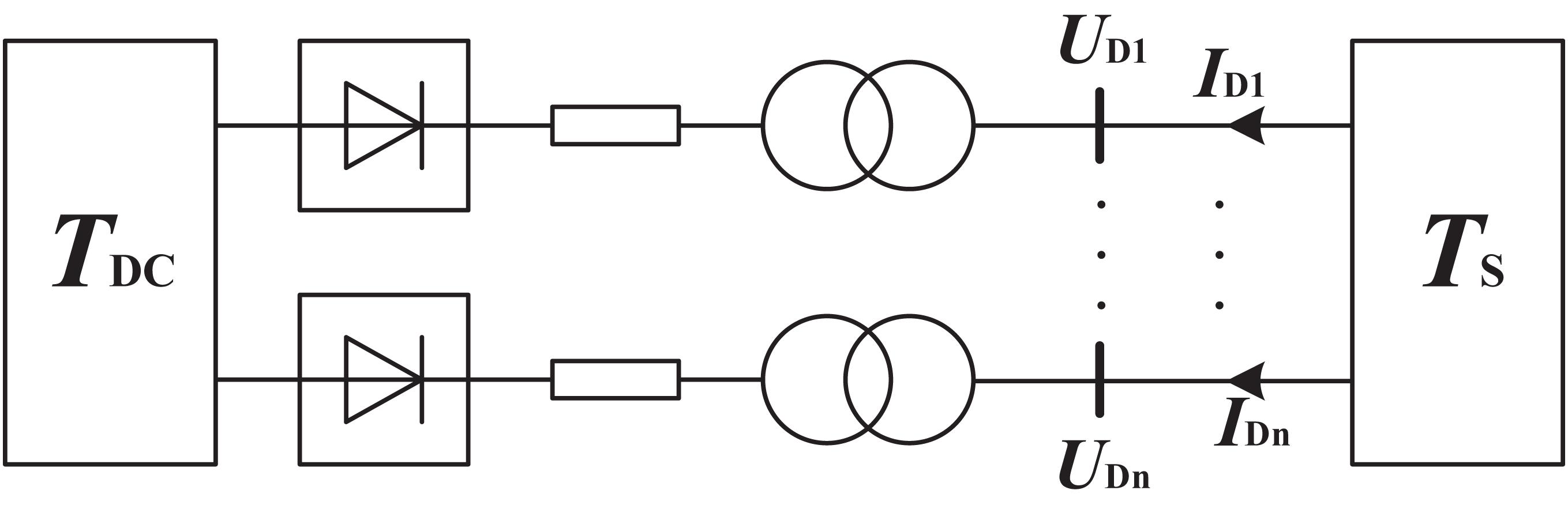
Figure 1. Common scheme of the hybrid simulation.
Matlab/Simulink is adopted as the EMT simulator and MatDyn is used for TS simulation. MatDyn is a Matlab-based open-source toolbox for power system stability analysis (Zheng et al., 2019). The power flow solution of MatDyn is obtained from MATPOWER and a complete program of transient stability simulation for the power system is provided. It is noteworthy that users can flexibly add user-defined models, including generator models, governor models, exciter models, and different kinds of user-provided Ordinary Differential Equation (ODE) solvers. While it is used in the hybrid simulation as a TS simulation program, the versatility of script files and flexibility of user-defined function will be beneficial for the follow-up research work. With an appropriate adjustment of MatDyn, it is encapsulated in Matlab Function (MF) which is a user-defined function block in the Matlab/Simulink library. The EMT simulation results are specified as input data to the MF block. MatDyn will execute for simulation and generate code for a Simulink Coder target. Furthermore, the simulation results of MatDyn are specified as output data of MF blocks and input data of the EMT simulation system. The basic structure of the hybrid simulation is established, so that the EMT simulation and TS simulation operate in parallel in MATLAB/Simulink.
The EMT and TS simulation are combined by a user-defined function of MATLAB/Simulink in this hybrid simulation structure. Because of its sufficient flexibility and applicability, it could operate on one PC, a local area network through distributed communication or a real-time simulation machine like RT-LAB.
Network Partition Scheme
The common scheme of a hybrid simulation for an AC/DC system is selecting the converter bus as the interface to partition EMT and TS subsystem (van der Meer et al., 2015). The HVDC system and bulk AC power system are simulated in the EMT and TS program, respectively. A multi-interface hybrid simulation should be established while the simulation object is the VSC-MTDC system (see Figure 1).
TS refers to the AC power system which is simulated in a TS simulation, TDC refers to the VSC-MTDC system which is simulated in the EMT simulation, UD refers to the vector of the converter bus voltage, ID refers to the vector of the converter bus current.
In this scheme, the detailed model of the VSC-MTDC system (i.e., the fast responding device) is established in the EMT simulation. The dynamic characters of converter values, control, and protection system could be simulated accurately by a microsecond simulation step. The VSC-MTDC system and AC system are completely decoupled in the hybrid simulation. It is worth mentioning that the AC system fault has a great influence on the VSC-MTDC system, especially when its fault point is nearby to the converter bus. In this case, the common scheme for hybrid simulation could not simulate the dynamic characters of the AC/DC system before or after the fault happens accurately. An improved scheme of hybrid simulation is proposed in this paper. Beyond that, the AC buses and generators which are near the converter buses are simulated in the EMT simulation, as shown in Figure 2.
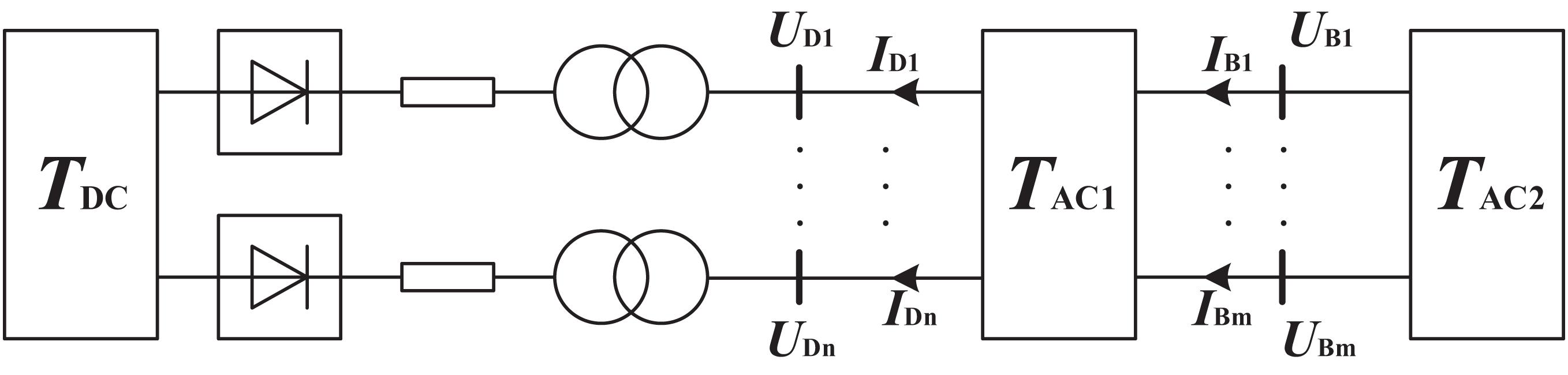
Figure 2. Improved scheme of the hybrid simulation.
TAC1 refers to the near-region AC system which is simulated in the EMT simulation based on a detailed EMT model, TAC2 refers to the other AC system which is simulated in the TS simulation, UB refers to the vector of multi-interface voltage, IB refers to the vector of the multi-interface current.
Two-interface hybrid simulation is taken as an example to illustrate the difference between the two hybrid simulation schemes. On the EMT simulation side, the TS subsystem is replaced by the Thevenin equivalence method. For illustrative purposes, the equivalent model and the mathematics model of EMT simulation could be represented as Figure 3.
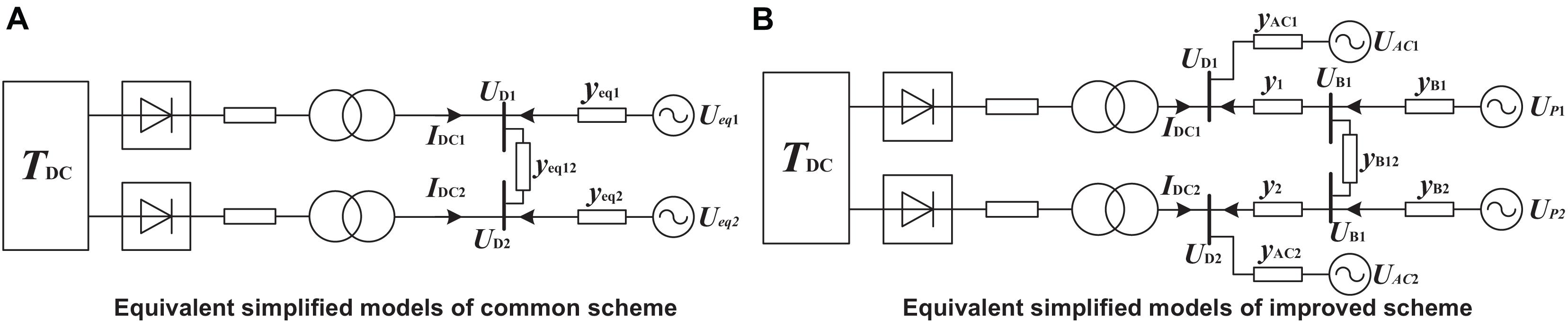
Figure 3. Schematic diagram of the hybrid simulation scheme. (A) Equivalent simplified models of the common scheme. (B) Equivalent simplified models of the improved scheme.
IDC1 and IDC2 refer to the currents of converter buses which are generated by the VSC-HVDC system, UD1 and UD2 refer to the voltages of converter buses, Ueq1 and Ueq2 refer to the voltages of Thevenin equivalent voltage source of TS subsystem, Up1 and Up2 refer to the voltages of Thevenin equivalent voltage source of TAC2 subsystem, Yeq1, Yeq2, and Yeq12 refer to the Thevenin equivalent impedance of TS subsystem, YB1, YB2, and YB12 refer to the Thevenin equivalent impedance of TAC2 subsystem, Y1 and Y2 refer to the mutual impedance between the converter buses and interface buses, UAC1 and UAC2 refer to the voltages of Thevenin equivalent voltage source of active region in TAC1 subsystem, YAC1 and YAC2 refer to the Thevenin equivalent impedance of active region in TAC1 subsystem.
According to Figure 3A, the node voltage equation of the converter bus in the common scheme is established, which can be expressed as formula (1):
In Figure 3B, the structure is more complex, and the node voltage equations of converter buses and interface buses in the improved scheme are established, respectively, which can be expressed as formula (2) and (3):
From formula (3), the voltage of interface buses can be formulated as:
where YBD and YBP are second order matrixes, which can be expressed as formula (5) and (6):
where ys refers to the substitution value of multiple admittance calculations, and its specific expression is shown as follows:
Substituting (4) into (2), the voltage of converter buses in the improved scheme can be expressed as:
In order to analyze the influencing factors of the converter buses’ voltages, the complex coefficient matrixes are replaced by different symbols, which can be expressed as follows:
The voltage of converter buses in the common scheme can be deduced and expressed from (1) in the same way:
where
The element admittance value of coefficient matrixes in formula (7) and (8) is obtained from actual system when it is established in the EMT simulation, and the equivalent admittance value of the TS subsystem is calculated by the multiport Thevenin equivalent method. In general, the simulation data interaction time is based on the TS simulation time step size, which is dozens or hundreds of the EMT simulation time step. According to the simulation theory of TS and EMT, the admittance of power system elements remains unchanged in one TS simulation time step. Hence, the elements of different coefficient matrixes are the fixed values.
Formula (7) and (8) can be, respectively, simplified as:
The EMT simulation step and TS simulation time step are, respectively, set as Δt and ΔT. Besides,ΔT is N times of Δt. In the process of the hybrid simulation based on the improved scheme or common scheme, the change of the converter bus voltage at time t+nΔt can be deduced as follows:
where n refers to the number of EMT simulation time steps during t and t+nΔt, ΔUDim refers to the change of the converter bus voltage from time t to t+nΔt when the hybrid simulation is based on the improved scheme, and ΔUDcom refers to the change of the converter bus voltage from time t to t+nΔt when the hybrid simulation is based on the common scheme.
The change of the converter bus voltage is an important influence factor that determines the operation status of the VSC-HVDC system. In a TS simulation time step, the interface voltage of the hybrid simulation remains unchanged, and the simulation accuracy of the VSC-HVDC system in the EMT simulation depends on the precision of the converter bus voltage. From (11) and (12), it can be concluded that ΔUDim is influenced by IDC and UAC, and ΔUDcom is only influenced by IDC in a TS simulation time step. While the improved scheme is adopted, the near-region AC system is simulated in the EMT simulation and its simulation step changes from ΔT to Δt. While a short-circuit fault or DC system fault happens on the power system, the improved scheme can effectively reduce the simulation error with the more accurate simulation results of a near-region AC system.
Interaction Process
A complete interaction process of hybrid simulation is related to the transmission mode of interface data between TS and EMT simulation. In previous research, there are two types of interaction processes used, namely the parallel and serial interaction process (Mugombozi et al., 2015). With the parallel interaction process, both simulator programs are running simultaneously, and the interface data is exchanged in each iteration by one TS simulation step. However, it could cause significant errors or singularities of the simulation system matrix when the large disturbance occurs in a large-scale power system. Additionally, with the serial interaction process, one simulator program must wait until the other completes the simulation of one interaction time step and transfers the interface data. The feature of the serial interaction process is not good for real-time simulation, but it could improve the convergence and accuracy of hybrid simulation when large disturbances occur in the simulation system. By comparing these two types of interaction processes, this paper finds that the serial interaction process is more suitable to be used in a hybrid simulation of a large-scale AC/DC power system.
The complicated data exchange process includes Thevenin equivalence, data conversion, data fitting, and boundary condition update.
The overall process from time t to time t+ΔT includes five main steps, as illustrated in Figure 4.
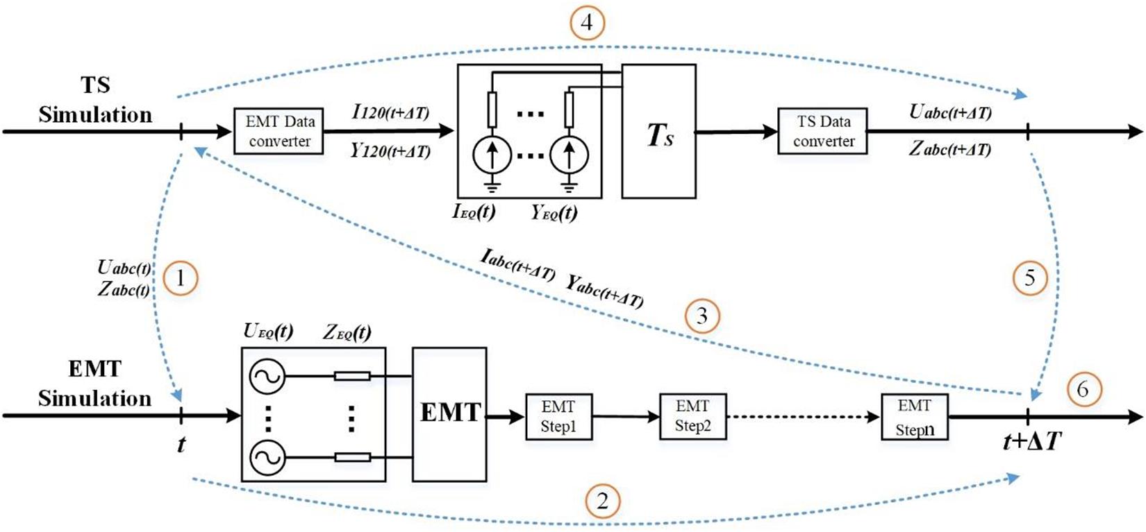
Figure 4. Interaction process of the hybrid simulation.
(1) Based on the simulation results of the electromechanical transient simulation at time t, the multi port Thevenin equivalent of the electromechanical transient side system is carried out with each interface bus, and the equivalent results of Uabc(t) and Zabc(t) are transmitted to the EMT simulation side through the hybrid simulation interface.
(2) In the EMT simulation side, the parameters of the Thevenin equivalent circuit at the interface are updated, and the EMT calculation is carried out for N times until t + ΔT.
(3) The EMT simulation results at the interface bus at t+ΔT time are transferred to the electromechanical transient side by Iabc(t+ΔT) and Yabc(t+ΔT), and the interface data is converted in the interface program. The EMT calculation results based on ABC three-phase are converted into positive and negative zero three sequence interface data I120(t+ΔT) and Y120(t+ΔT) for electromechanical transient.
(4) The electromechanical transient simulation side updates the Norton equivalent circuit parameters at the interface, calculates the electromechanical transient once, and runs to t + Δ t time.
(5) At t + Δ t time, the data of the electromechanical transient simulation results U120(t+ΔT) and Z120(t+ΔT) at the interface bus are converted into the data of the ABC three-phase interface U120(t) and Z120(t), which are suitable for EMT. In addition, the data is transferred to the EMT side. Step (1) is repeated to start the next phase cycle until the hybrid simulation ends.
Simulation Results
This section reports simulation results obtained with the Zhangbei multi-terminal VSC-HVDC transmission system which had been put into operation in 2020. The topology of the AC/DC system is shown in Figure 5.
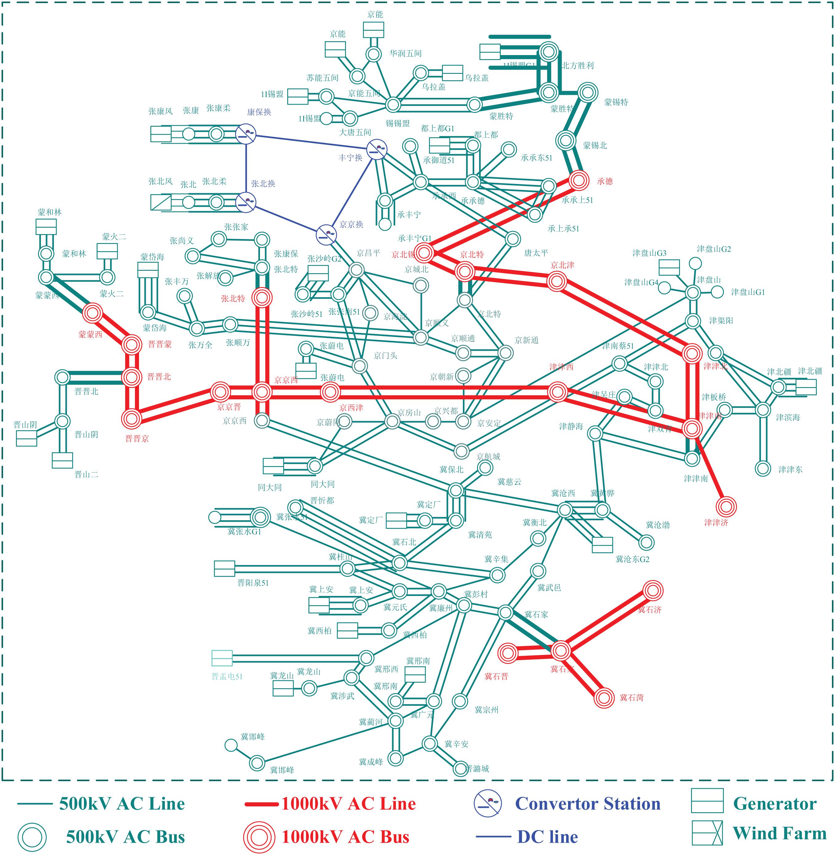
Figure 5. Topology of the Zhangbei multi-terminal VSC-HVDC transmission system.
It is essential to build the full electromagnetic simulation model and the electromechanical electromagnetic hybrid simulation model to verify the accuracy of the hybrid simulation. However, the huge network scale and complexity of the Sanhua power grid are not conducive to the construction of the full electromagnetic simulation model. Therefore, this paper uses the equivalent system of the Zhangbei four-terminal flexible DC power grid in reference (Chen et al., 2020) as the actual simulation example to build a hybrid simulation real platform. The Shanxi power grid connected by the Shanxi Beijing tie line is equivalent to two equivalent generators in Jinjing and Jindatong, the Inner Mongolia Chengde and Inner Mongolia Beijing tie line are equivalent to two equivalent generators in Mengxibei and Tuohunyuan, Zhangjiakou is equivalent to two equivalent generators in Zhangbeite and Zhangshunwan, and Chengde is equivalent to one equivalent generator in Chengyudao. The original system of Dushangdu, Zhangweidian, Zhangshaling, and Jinpanshan generators are retained, and Jinpanshan in the system is the reference generator node. The dynamic characteristics of the equivalent system of the Zhangbei DC power grid are verified in reference (Chen et al., 2020), which can fully characterize the dynamic characteristics of the original Zhangbei flexible DC power grid and its nearby AC system. Figure 6 shows the equivalent system topology of the Zhangbei DC power grid.
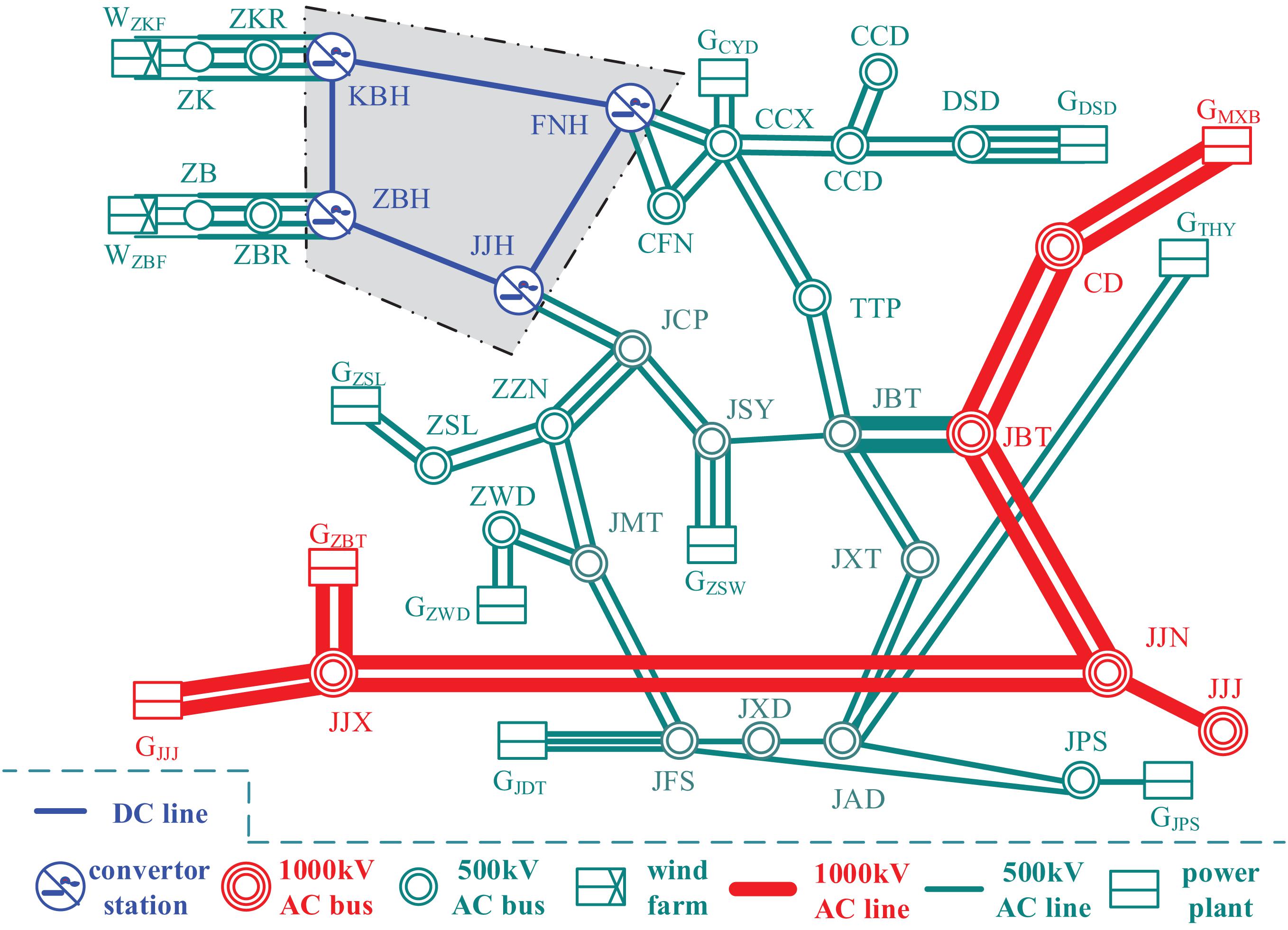
Figure 6. Topology of the equivalent system.
According to the hybrid simulation method proposed in this paper, the AC system of the Zhangbei flexible DC power grid and its adjacent area which needs small step-length detailed simulation is divided into the EMT simulation side, and the EMT simulation modeling is conducted on the Simulink / Matlab platform. Among them, there are five generators at bdsd of Dushangdu bus, which is close to Fengning converter station, and one generator at bcyd of Chengyudao bus. All of them adopt five-order generator models for EMT modeling, while retaining detailed excitation and a speed control system. 500 kV AC bus Tangtaiping bttp and Jingchangping bjcp are selected as the hybrid simulation interface bus. The rest of the AC system is modeled in matdyn open-source software based on the MATLAB platform. Figure 7 is the schematic diagram of the specific distribution scheme.

Figure 7. Decomposition in the TS and EMT subsystems.
In the hybrid simulation, the Runge Kutta method is adopted to solve the stability of electromechanical transient simulation. The simulation step is Δt = 0.02 s, and the third-order dynamic model is used for the generator. The trapezoidal method is used to solve the EMT simulation in the Simulink platform. The fixed step mode is adopted, and the step size is Δ t = 50 μ s. In the hybrid simulation, the AC system parameters adopt the Fengda operation mode of the Sanhua power grid in 2018, and the parameters of the Zhangbei multi terminal DC system are shown in Table 1.
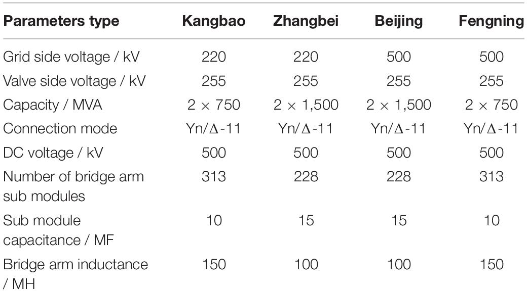
Table 1. Parameters of the zhangbei multi terminal flexible dc system.
At the same time, the paper builds a full electromagnetic simulation model of the Zhangbei DC power grid equivalent system. Its system structure and parameters are identical with the hybrid simulation model of the Zhangbei DC power grid. Beyond that, the simulation results of the two models are compared to verify the accuracy and effectiveness of the hybrid simulation method proposed in this paper. A three-phase short circuit fault is set at the Jingxintong bus, with a fault duration of 0.1 s. The dynamic characteristics of AC and DC system at the electromechanical transient simulation side, EMT simulation side, and interface bus are compared, respectively, and the accuracy of the hybrid simulation method proposed in this paper is verified.
Figures 8, 9 compare the dynamic characteristics of GZWD and GDSD under different simulation conditions. Among them, the generator GDSD is located in the EMT simulation side of the hybrid simulation model. As shown in Figure 10, its dynamic characteristics in the hybrid simulation model are basically consistent with those in the full electromagnetic simulation condition. The generator GZWD is located in the electromechanical transient simulation side of the hybrid simulation model. As displayed in Figure 9B, the simulation results of its excitation voltage are slightly different under the two simulation conditions, which is due to different simulation algorithms. From the occurrence of the three-phase short-circuit fault to the first electromechanical transient step time, the generator and its excitation controller in the EMT are in a relatively continuous operation state, and the state of the generator changes with time and is synchronized with the whole simulation system. Hence, the excitation voltage increases to the maximum state in a diagonal line through the integral control link. In the electromechanical transient calculation environment, the generator directly calculates to an electromechanical transient step, the time span is large, and the controller in its exciter cannot play an integral role. Thus, the excitation voltage increases in a straight-line form after the fault, and the maximum values in this example are higher than the calculation results of EMT simulation. This further leads to the difference of simulation results of gzwd transient recovery process after fault removal, but the overall recovery time is basically the same. As displayed in Figure 9A, the difference between the simulation results of generator output power is small. Therefore, the hybrid simulation method proposed in this paper is basically accurate for the simulation of generator dynamic characteristics.
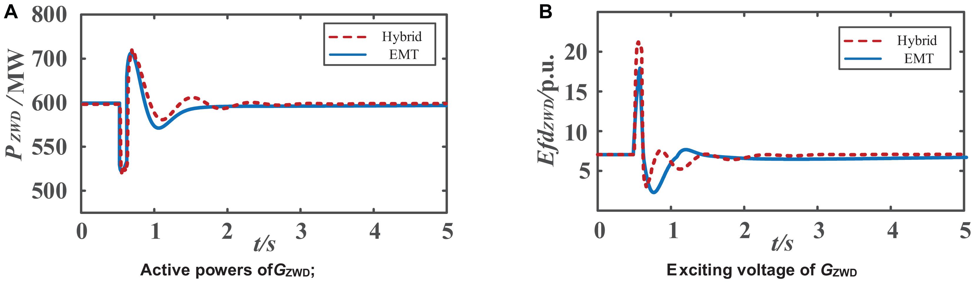
Figure 8. Dynamic characteristics of generators in the TS simulation; (A) Active powers of GZWD; (B) Exciting voltage of GZWD.
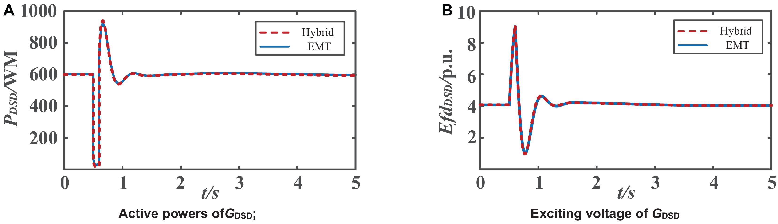
Figure 9. Dynamic characteristics of generators in the EMT simulation; (A) Active powers of GDSD; (B) Exciting voltage of GDSD.
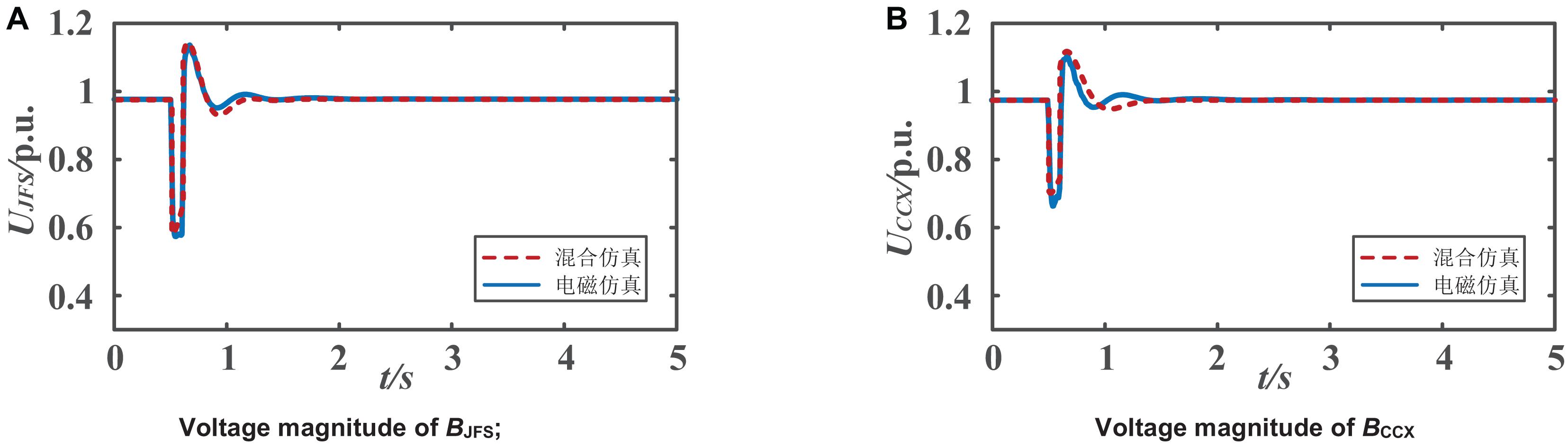
Figure 10. Comparisons of voltage magnitude; (A) Voltage magnitude of BJFS; (B) Voltage magnitude of BCCX.
Figures 10A,B show the voltage amplitude dynamic characteristics of the electromechanical transient bus BJFS and the EMT bus BCCX, respectively. Figure 11 shows the voltage amplitude dynamic characteristics of BJCP and BTTP. It can be seen that the simulation results of the AC system in the hybrid simulation model are basically consistent with all the EMT simulation models, and more accurate calculation results have been obtained.
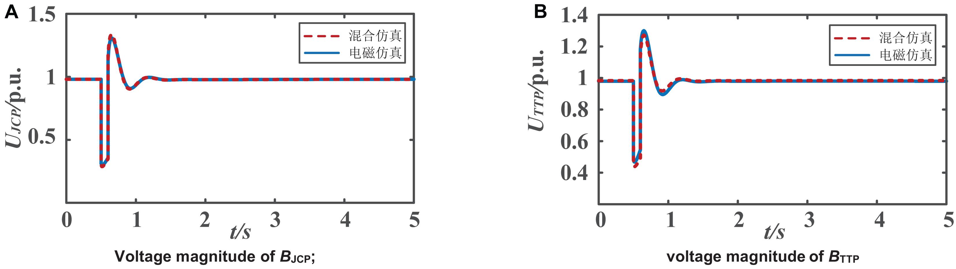
Figure 11. Comparisons of voltage magnitude of interface buses; (A) Voltage magnitude of BJCP; (B) Voltage magnitude of BTTP.
Figures 12, 13 show the dynamic characteristics of the DC voltage and DC current of the Beijing converter station and Zhangbei converter station in the DC power grid, respectively. The calculation results of the hybrid simulation model are basically consistent with the total EMT model. For the simulation of the DC system, whether it is under mixed simulation or full EMT simulation, the real matter is to model the DC system in EMT software, without any difference in calculation method, step size, and underlying model. Whether the simulation results are accurate mainly depends on the dynamic characteristics of bus at the AC/DC interface, but the simulation of the dynamic characteristics of the whole AC system is accurate. The significance of the hybrid simulation is to save the huge workload and computing resources in order to build the full EMT simulation model. The detailed EMT modeling is carried out for the key research objects, and the complete system scale can be kept as much as possible.
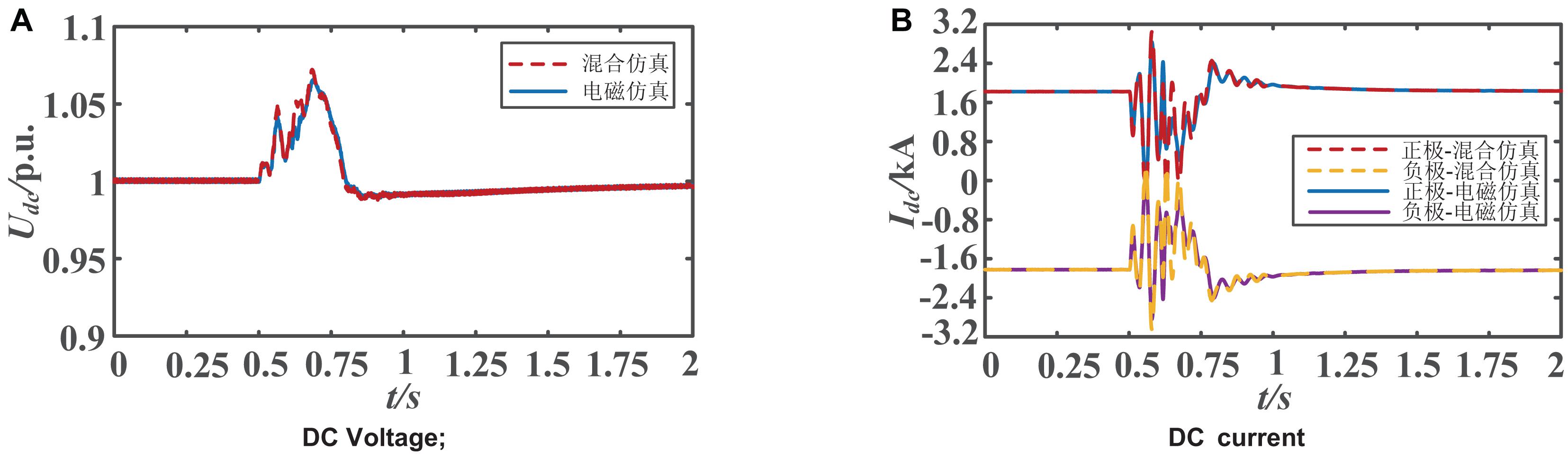
Figure 12. Dynamic characteristics of Zhangbei station; (A) DC Voltage; (B) DC current.
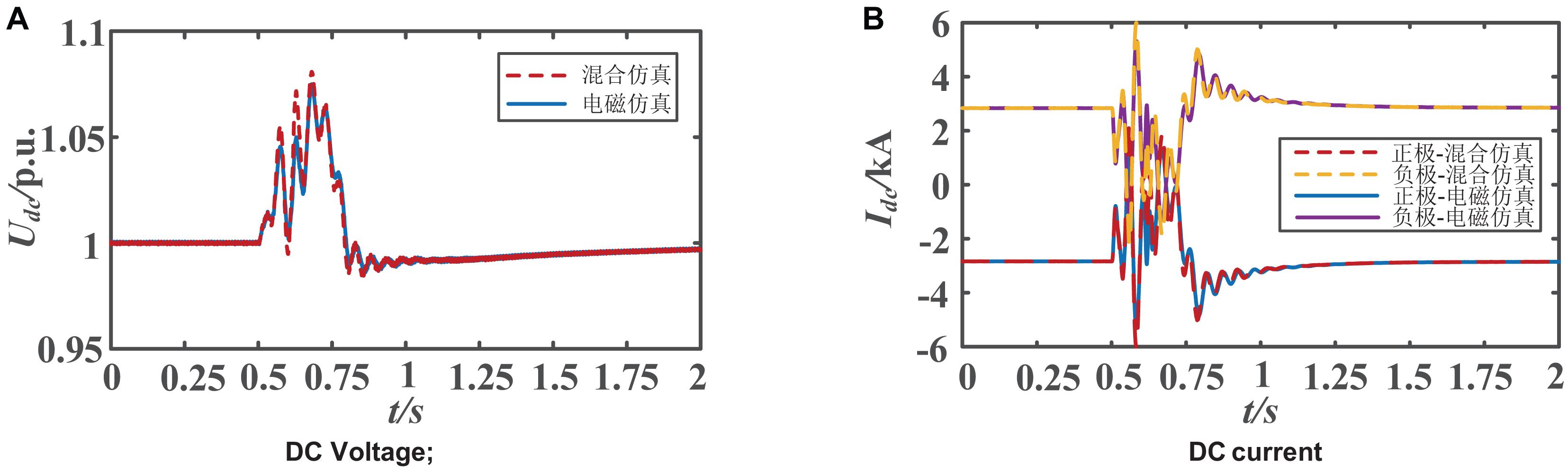
Figure 13. Dynamic characteristics of Beijing station; (A) DC Voltage; (B) DC current.
In conclusion, the hybrid simulation model based on the equivalent system of the Zhangbei DC power grid can not only accurately simulate the dynamic characteristics of the AC system in the electromechanical transient side, EMT side, and hybrid simulation interface bus, but also fully and accurately simulate the dynamic characteristics of the Zhangbei DC system. Therefore, the accuracy and correctness of the proposed hybrid simulation method can be verified.
Conclusion
This paper has proposed a hybrid simulation method based on MATLAB/Simulink. Specifically, the user-defined function module provided by Simulink is used, and the matdyn toolkit is integrated into it. Furthermore, the electromechanical transient simulation program is written to realize the parallel operation of the electromechanical transient simulation and EMT simulation on the same platform.
Aiming at the electromechanical electromagnetic hybrid simulation of the AC/DC hybrid system, this paper proposes that some AC power grids with a great influence on the DC system should be reserved in the EMT simulation side, which can more accurately simulate the interaction of the AC/DC system and improve the accuracy of the hybrid simulation. At the same time, the specific implementation method of electromechanical electromagnetic hybrid simulation is described in detail. In the interface program, the serial data iteration process is adopted, and the real-time update and conversion of equivalent circuit parameters are realized in the data interaction process, which ensures the stability and accuracy in the hybrid simulation calculation process. Finally, through the actual system of the Zhangbei DC power grid, this paper not only compares the results of the hybrid simulation model with those of all the electromagnetic simulation models, but also verifies the accuracy of the proposed hybrid simulation method and the practicability of applying it to a large-scale AC/DC system simulation.
The future research will focus on the following two aspects:
(1) Scientific Selection of the interface bus. In the hybrid simulation, the selection of the interface bus also depends on the manual selection of staff, which means that scientific planning scheme and calculation method should be established considering the interaction of the AC and DC system and the limitation of simulation resources.
(2) Adaptive problem of hybrid simulation. The hybrid simulation method proposed in this paper is mainly for an AC/DC power grid with VSC HVDC. If the hybrid simulation model is carried out for an AC/DC system including LCC HVDC or hybrid DC, it is essential to optimize the interface algorithm and implementation method so as to improve the applicability of the hybrid method, which deserves further research and discussion.
Data Availability Statement
The original contributions presented in the study are included in the article/supplementary material, further inquiries can be directed to the corresponding author/s.
Author Contributions
SZ and SL designed the model and the computational framework and analyzed the data. SZ and XL carried out the implementation. SL performed the calculations. SZ and GL wrote the manuscript with input from all authors. GL conceived the study and were in charge of overall direction and planning.
Conflict of Interest
The authors declare that the research was conducted in the absence of any commercial or financial relationships that could be construed as a potential conflict of interest.
References
Chen, H., Wang, W., Jiang, T., Wei, J., Zhang, S., and Li, G. (2020). Data-driven Dynamic Equivalence Method in Bulk Power Systems. Power Syst. Tech 44, 3047–3056.
Huang, Q., and Vittal, V. (2017b). Integrated Transmission and Distribution System Power Flow and Dynamic Simulation Using Mixed Three-Sequence/Three-Phase Modeling. IEEE Trans. Power Syst. 32, 3704–3714. doi: 10.1109/tpwrs.2016.2638910
Huang, Q., and Vittal, V. (2017a). Advanced EMT and phasor-domain hybrid simulation with simulation mode switching capability for transmission and distribution systems. IEEE Trans. Power Syst. 33, 6298–6308. doi: 10.1109/tpwrs.2018.2834561
Li, Y., Wang, C., Li, G., and Chen, C. (2021). Optimal scheduling of integrated demand response-enabled integrated energy systems with uncertain renewable generations: a Stackelberg game approach. Energy Convers. Manag. 235:113996. doi: 10.1016/j.enconman.2021.113996
Liming, S., and Bo, Y. (2020). Nonlinear robust fractional-order control of battery/SMES hybrid energy storage systems. Power Syst. Prot. Control. 48, 76–83.
Mugombozi, C. F., Mahseredjian, J., and Saad, O. (2015). Efficient computation of feedback-based control system equations for electromagnetic transients. IEEE Trans. Power Deliv. 30, 2501–2509. doi: 10.1109/tpwrd.2015.2446532
Plumier, F., Aristidou, P., Geuzaine, C., and Van Cutsem, T. (2016). Co-Simulation of Electromagnetic Transients and Phasor Models: a Relaxation Approach. IEEE Trans. Power Deliv. 31, 2360–2369. doi: 10.1109/tpwrd.2016.2537927
Schneider, K. P., Tuffner, F. K., Elizondo, M. A., Hansen, J., Fuller, J. C., and Chassin, D. P. (2019). Adaptive dynamic simulations for distribution systems using multi-state load models. IEEE Trans. Smart Grid 10, 2257–2266. doi: 10.1109/tsg.2018.2794180
Shu, D., Xie, X., Dinavahi, V., Zhang, C., Ye, X., and Jiang, Q. (2018). Dynamic Phasor Based Interface Model for EMT and Transient Stability Hybrid Simulations. IEEE Trans. Power Syst. 33, 3930–3939. doi: 10.1109/tpwrs.2017.2766269
van der Meer, A. A., Gibescu, M., van der Meijden, M. A. M. M., King, W. L., Ferreira, J. A., et al. (2015). Advanced hybrid transient stability and EMT simulation for VSC-HVDC systems. IEEE Trans. Power Deliv. 30, 1057–1066. doi: 10.1109/tpwrd.2014.2384499
Venkatraman, R., Khaitan, S. K., and Ajjarapu, V. (2019). Dynamic co-simulation methods for combined transmission-distribution system with integration time step impact on convergence. IEEE Trans. Power Syst. 34, 1171–1181. doi: 10.1109/tpwrs.2018.2874807
Zhang, Y., Gole, A. M., Wu, W., Zhang, B., and Sunet, H. (2013). Development and analysis of applicability of a hybrid transient simulation platform combining TSA and EMT elements. IEEE Trans. Power Syst. 28, 357–366. doi: 10.1109/tpwrs.2012.2196450
Keywords: hybrid simulation, HVDC, transient stability, Thevenin equivalent, electromagnetic transient
Citation: Zhang S, Li G, Li S and Liu X (2021) Hybrid Simulation for Large-Scale AC/DC Power System by Serial Interaction Process. Front. Energy Res. 9:686566. doi: 10.3389/fenrg.2021.686566
Received: 27 March 2021; Accepted: 12 April 2021;
Published: 21 May 2021.
Edited by:
Bo Yang, Kunming University of Science and Technology, ChinaReviewed by:
SHi Peng, Shanghai Jiao Tong University, ChinaMingqiang Wang, Shandong University, China
Copyright © 2021 Zhang, Li, Li and Liu. This is an open-access article distributed under the terms of the Creative Commons Attribution License (CC BY). The use, distribution or reproduction in other forums is permitted, provided the original author(s) and the copyright owner(s) are credited and that the original publication in this journal is cited, in accordance with accepted academic practice. No use, distribution or reproduction is permitted which does not comply with these terms.
*Correspondence: Song Zhang, emhhbmdzb25nbmVlcHVAYWxpeXVuLmNvbQ==