- School of Mechanical Engineering, Shanghai Jiao Tong University, Shanghai, China
During the process of containment depressurization venting, a high-temperature and high-pressure carrier gas with aerosol may be released into the spent fuel pool by a multihole injector. This aerosol in the carrier gas can be removed by pool scrubbing. A small-scale pool scrubbing facility was built to study the aerosol pool scrubbing phenomenon using a multihole injector. In this study, a gaseous mixture of nitrogen and steam is used to simulate a carrier gas, and insoluble solid particles of TiO2 are used to simulate aerosols in the carrier gas. Seven tests were performed to examine the dependence of the decontamination factor (DF) on the pool depth, particle diameter, and steam mass fraction. The results show that log(1/(1–Xm)) has a linear relationship with log(DF). DF varies exponentially with the pool depth, which has an influence on the retention of aerosols with a larger particle diameter. Particle diameters in the range of 0.2–0.52 μm have little effect on the DF. For a low-depth pool scrubbing, the steam condensation mechanism is dominant and the particle diameter does not have a significant effect on the DF. Moreover, the pool scrubbing model is discussed, and an empirical correlation is proposed to evaluate the DF of a pool.
Introduction
During a severe accident in a nuclear power plant, substantial amounts of radioactive fission products are released into the containment, as aerosol is released from the degraded core with steam entrainment. Containment venting is adopted as a depressurization and filtration strategy to mitigate the consequence of releasing numerous fission products into the environment due to overpressure failure of the containment (Huang et al., 2010). To improve the filtration availability of containment depressurization venting after the accident measures have been undertaken, the CAP1400 reactor uses the spent fuel pool (SFP) as a place to remove aerosols from the carrier gas injected by a multihole injector (Gao et al., 2017). When the carrier gas passes through the pool, aerosol can be removed by steam condensation, inertial impaction, gravity deposition, centrifugal deposition, and Brownian diffusion (Wassel et al., 1985; Kaneko et al., 1992). The pool acts as a physical filter to remove the aerosol. An accurate knowledge of the pool scrubbing process is necessary to evaluate the effect of the decontamination factor (DF) of the spent fuel pool (SFP) on aerosol removal.
In addition to containment depressurization venting progress, the phenomenon of pool scrubbing occurs in the pressurizer or quench tank of a pressurized water reactor, or the pressure suppression pool of a boiling water reactor. Several pool scrubbing experiments were conducted in the 1980s and 1990s; among these, prominent works include the following (Escudero et al., 1995): the EPRI, EPSI, and SPARTA experiments. The EPRI experiment studied the aerosol pool scrubbing phenomenon at lower flow rates (<7.1 m/s). However, due to the different flow patterns of the carrier gas, the results of these experiments are not suitable for the scrubbing process under the condition of high-velocity injection. The EPSI experiment studied the effect of high pressure (>1.1 MPa) and high temperature (>273°C) on the pool scrubbing behavior. However, the experiment was carried out at a low flow rate, and the effect of insoluble solid particles was not investigated. The SPARTA experiment ignored the effect of steam condensation and considered the high-temperature pool scrubbing phenomenon with noncondensable gases as the carrier gases. Due to the different research objects, the thermal hydraulic parameters of the abovementioned experiments are completely different from the SFP scrubbing phenomenon in the process of containment depressurization venting.
Dehbi et al. (2001) conducted the POSEIDON-II experiment with 17 tests to study the effects of pool depth, steam mass fraction, and particle diameter on the DF in low-subcooling pools during the process of a single-hole injection. Sun et al. (2019) studied the dependence of DF on the aerosol concentration in pool scrubbing with a single-hole injection. However, the thermal hydraulic characteristics of a single-hole injection and multihole injection are different, such as the steam condensation regime (Park et al., 2007), interaction of holes (Cho et al., 2004), and condensation oscillation characteristic (Hong et al., 2012). These differences lead to changes in the mechanism of aerosol condensation removal, bubble breakage, and inertial impact during the scrubbing process. The LACE-Espana experiment (Marcos et al., 1994) shows that the multihole injector has higher levels of retention than when performed using a single orifice; however, only one such test has been published and systematic studies are lacking. The ACE experiment (Escudero et al., 1995) investigates the aerosol pool scrubbing phenomenon under the condition of multihole injection and low steam volume fraction (<0.41). However, a higher steam volume fraction would result in more particles being trapped by steam condensation, which would change the effect of the inertial interception and steam condensation mechanism on aerosol retention.
The aerosol pool scrubbing effect was first described by Fuchs (Fuchs, 1964). In this model, the dominant scrubbing processes occur inside the rising bubbles. Wassel et al. (1985) introduced a pool scrubbing model which has become the basis of several pool scrubbing analysis codes. Computational codes such as BUSCA (Ramsdale et al., 1991) and SPARC (Owczarski et al., 1985) were developed after adequate studies had been conducted on retention in pools. Kaneko et al. (1992) also developed an empirical model for pool scrubbing using the existing scrubbing models and experimental results. The assessment of the pool scrubbing phenomenon under a multihole injector needs further study.
In order to obtain an accurate knowledge of the mechanism of the pool scrubbing phenomenon in the parameter range of SFP and evaluate the effect of DF on aerosol removal including model development and verification for SFP, a small-scale aerosol pool scrubbing facility (SAPOS) was established. In this article, the DF is studied under different operational conditions (steam mass fraction, pool depth, and particle diameter). TiO2 powder is used as a simulant for the aerosols in containment, and a mixture of nitrogen gas and steam is used to simulate the carrier gas. A simplified model is expected to be developed for aerosol removal by analyzing the experimental results.
Materials and Methods
Experimental System
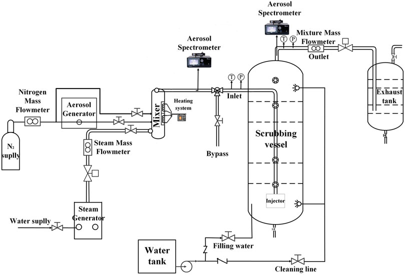
The SAPOS facility consists of a test vessel, gas supply system, and aerosol generation and measurement systems (Figure 1). The test vessel is a cylindrical pressure vessel 5 m high and 1 m in diameter. The pool comprises resistance temperature detectors, located at eight different levels, with three detectors placed 120° from each other at every level. A downward vertical vent pipe with six holes (1 cm in diameter) is used as the multihole injector. The six holes are divided into two groups and are symmetrically distributed on the pipe. The bottom of the multihole injector is 50 cm above the bottom of the vessel.
The gas supply system consists of a nitrogen supply system and a steam generator. A mass flow meter is used to measure the flow rate of nitrogen and steam. The nitrogen supply system provides two gas supplies, one for the carrier gas of the aerosol generator and the other for the noncondensable gas in the experiment, which is directly passed into the mixer. Electric heat tracing is arranged on the steam pipe and nitrogen pipe. The steam leaves the steam generator at 180°C and 7 bar and is superheated at the outlet to 180°C for the injecting mixer.
TiO2 particles are used to stimulate an experimental aerosol generated by the aerosol generator RBG 2000 SD (Palas GmbH). The aerosol generator disperses the particles using pure nitrogen as the carrier gas, and the powder is conveyed onto a rotating brush at a precisely controlled feed rate and pulled out of the brush by the nitrogen flow. When the aerosol powder flow rate is precise, the aerosol generator produces stable and repeatable particle diameter distributions.
The nitrogen, steam, and aerosol are combined in a mixer. The aerosol mixture is then passed into the pool through a submerged pipe.
Measurement Methods
The temperature, pressure, and flow of the carrier gas at the inlet and outlet and the water temperature, liquid level, concentration, and particle diameter of the aerosol at the inlet and outlet are measured and recorded. An aerosol spectrometer (Promo 3000 HP) with two probes is attached to the inlet and outlet of the pool to continuously monitor the aerosol concentrations and size distribution. The measured particle diameter is 0.15–10 μm, and the measured concentration is 106 P/cm3. The inlet aerosol mass median diameter (MMD) measured by using the spectrometer is 0.5 μm.
The average concentration is used to calculate the DF because of the steady inlet flow rate. The average DF is expressed as follows:
where Sin and Sout represent aerosol mass in and out of the test vessel, respectively. Cm-in and Cm-out denote the inlet and outlet aerosol mass concentrations, respectively. Qin and Qout represent the inlet and outlet volume flow, which can be calculated by the mass flow rate and carrier gas density. When Sin and Sout are the mass concentrations of aerosol for a particular particle diameter, the obtained value represents the DF of the pool for the aerosol of this particle diameter.
Uncertainty Analysis
The function f (x1,x2,. . ., xn) is calculated from the measured quantities x1, x2,. . ., xn with uncertainties σx1, σx2, . . ., σxn. The total uncertainty, σy, is calculated by the error transmission formula proposed by Moffat, 1988:
The DF is calculated as shown in Eq. 1, and the detailed uncertainty calculation for the DF is expressed in the following equations:
The TiO2 concentration at the inlet and outlet is measured after calibration of the aerosol spectrometer with the membrane filter measurements. The stainless-steel filter holder into which the PTFE filter (0.1 μm) is installed is at the back end of the measuring probe of the aerosol spectrometer, and the flow rate of 5 L/min is controlled by the mass flow controller. The calibration results show that the measurement error of the aerosol mass concentration of aerosol spectrometer is approximately 20%.
The inlet and outlet volume flow are calculated using Eq. 5, and the uncertainty calculations for the volume flow are expressed in the following equations:
where Q represents the volume flow, Qm is the mass flow with an accuracy of 1%, T and P denote the temperature and pressure of the fluid, and the error is ±1°C and ±1.0% full scale, respectively. R is the ideal gas constant. M is the molar mass fraction.
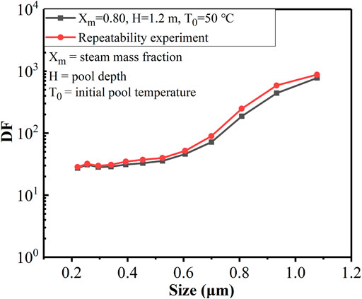
In addition, a repetitive experiment was carried out to check the experimental uncertainty. As shown in Table 1, SF1 and SF1-R were carried out under the same experimental conditions. The average experimental DFs (averaged over the whole experiment) of two results are 39 and 42, respectively. As shown in Figure 2, the DFs of the two experiments are consistent for different particle diameters.
Results and Discussion
Seven tests were performed in this study under the same experimental conditions except the pool depth and steam mass fraction. This strategy allows analysis of the effect of pool depth and steam mass fraction on DF without the effect of other parameters. The hydrothermal and aerosol phenomena in SF1 are described as an example. The results of all the seven tests are compared and discussed.
Pool Scrubbing Phenomenon
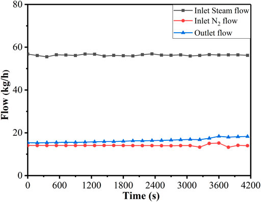
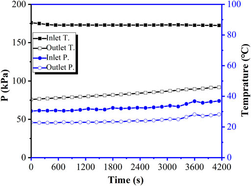
In SF1, the steam mass fraction is 0.8, pool depth is 1.2 m, initial temperature of the pool is 50°C, and the total mass flow of nitrogen and steam at the inlet is 70 kg/h. The experiment lasted for 4,200 s from the time the aerosol entered the pool. The nitrogen flow and steam flow at the inlet are stable at 56.30 kg/h and 14.07 kg/h, respectively, and the average value of the outlet flow is 16.44 kg/h, as shown in Figure 3. This indicates that the outlet contains a small amount of steam. The injection gas temperature is maintained at approximately 170°C, as shown in Figure 4. The average injection pressure is 32.71 kPa (g), and there is a slight increase in pressure at the inlet, which is primarily caused by the rise of pressure above the vessel.
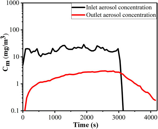
Figure 5 shows the variation in the aerosol mass concentration at the inlet and outlet, which indicates that the aerosol concentration at the outlet decreases slightly when the aerosol feed is halted at 3,100 s. This also shows the accumulation of aerosol above the water surface. Nitrogen and steam continue to be injected until the concentration of aerosol at the outlet reaches below 500 P/m3, and then, the experiment stops. The average mass concentrations of the inlet and outlet are calculated to be 13.27 mg/m3 and 1.73 mg/m3, respectively. Eq 1 is used to obtain the average experimental DF of 39 ± 14, along with a 95% confidence interval.
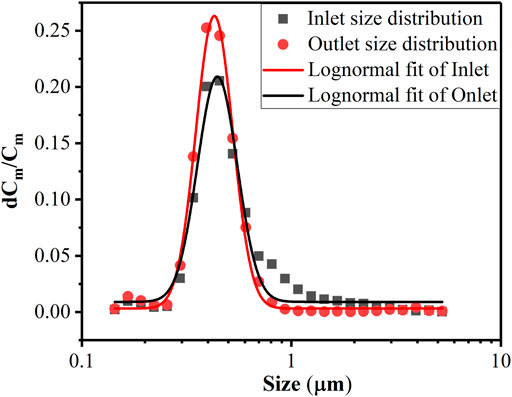
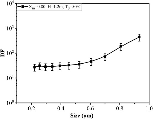
Figure 6 demonstrates the size distribution of aerosol for the tests, depicting a log-normal distribution, and the MMD and geometric standard deviation (GSD) are 0.50 μm and 1.255, respectively. The particle diameter of aerosols is primarily between 0.2 and 1 μm. The larger particles are retained during pool scrubbing. The MMD and GSD of the aerosol at the outlet are 0.43 μm and 1.225, respectively, which are lower than those at the inlet. Owing to the high resolution of the Promo 3000 HP, the particle-diameter–dependent DF for each experiment can be obtained. Such information is essential in determining the range at which the various aerosol removal mechanisms become dominant. For SF1, the DFs of 11 different particle diameters are shown in Figure 7.
Influence of Steam Mass Fraction on DF
The effect of different steam mass fractions on average DFs of aerosol is investigated in experiments SF1, SF2, SF3, and SF4. As shown in Table 1, the average DF increases from eight at a steam mass fraction of 0.5 to 197 at a steam mass fraction of 0.9 with the same MMD of 0.5 μm (the retention efficiency increases from 87.5 to 99.5%).
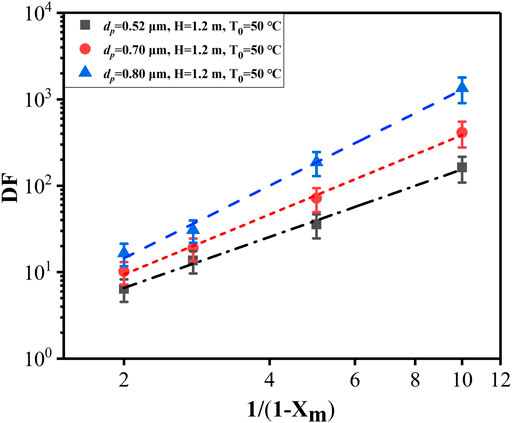
The DFs versus different steam mass fractions at different particle diameters are shown in Figure 8. The higher the steam fraction, the greater the influence of the steam condensation mechanism on aerosol retention and the larger the DF. The steam condensation effect leads to the destruction of the uniformity of gas mixing in the carrier gas, and the steam is constantly migrated to the gas–liquid interface, driving the aerosol to migrate to the gas–liquid interface and strengthening the removal of aerosols. The higher the steam mass fraction, the stronger the heat transfer between the carrier gas and the pool, the more the aerosols are carried to the gas–liquid interface by steam, and the stronger the enhancement effect of the steam condensation mechanism on DF. In addition, as the steam mass increases, the amount of aerosol deposition increases due to the condensation. The results of data analysis show that log(1/(1−Xm)) has a linear relationship with log (DF).
Influence of Pool Depth on DF
The effect of different pool depths (1.2, 1.8, 2.4, and 3.0 m) on the average DFs of aerosol is investigated by fixing the carrier gas flow rate at 70 kg/h. It can be seen from Table 1 that the average DFs increased from 15 at a pool depth of 1.2 m to 260 at a submerged depth of 3.0 m with the same MMD of 0.5 μm and the same steam mass fraction of 0.64 (the retention efficiency increases from 93.3 to 99.6%).
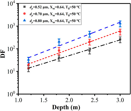
The DFs versus different pool depths at different particle diameters are showed in Figure 9, which shows a linear relationship between log (DF) and pool depth that means the DF increases exponentially with the growth of pool depth. The larger the particle diameter, the greater the slope of the growth curve, which indicates that the pool depth has a greater influence on the retention of aerosols with a larger particle diameter (0.4–0.7 μm). The higher the pool depth, the more the time it takes for the carrier gas to escape from the pool and the longer the inertial impact and gravitational settling mechanisms act, which leads to a greater possibility of the large particles being trapped.
Influence of Particle Diameter on DF
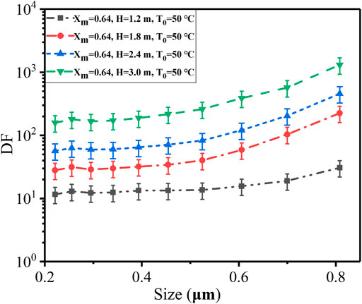
Figure 10 shows the DFs of different particle diameters at different pool depths (1.2, 1.8, 2.4, and 3.0 m). The DF increases with the growth of particle diameters at all pool depths. This is because of the effect of inertial impaction and gravity settling caused by the particle diameter during injection and rise regions. In the case of particle diameter less than 0.52 μm, the DF hardly changes, while for particle diameter greater than 0.52 μm, the DF increases rapidly, which reveals that the influence of inertial impaction and gravity settling on the DF is dominant for large particles (>0.52 μm). For particle diameters in the range of 0.2–0.52 μm, the particle diameter has little effect on the DF.
At low pool depth, most particles are removed in the injection region due to steam condensation. It can be seen from the experimental results that for a low-depth pool scrubbing, the particle diameter has little effect on the DF.
Mechanistic Scrubbing Model
In the existing scrubbing model, the pool scrubbing process is divided into the injection region and rise region. During the pool scrubbing process, the carrier gas leaves the injector to form large bubbles, which break up into a swarm of small bubbles as the gas rises in the pool. These bubbles rise to the surface of the pool under the influence of buoyancy.
Mechanism at the Injection Region
In the injection region, condensation of steam occurs around the injection point, and aerosol is removed by condensed steam in the pool water. A simple model can be used to represent the steam condensation removal effect. The SPARC code assumed that the DF caused by steam condensation equals the fractional loss in gas volume caused by condensation, and the aerosol concentration in the carrier gas is uniform throughout the scrubbing process (Owczarski et al., 1985).
As found by these tests, the estimation of particle retention due to steam condensation in this way alone is insufficient. Steam condensation in a pool occurs at the gas–liquid interface between the bubble and water. Steam condensation on the surface of the bubble causes the steam in the bubble to flow continuously to the gas–liquid interface, and the noncondensable gas is squeezed to the center of the bubble, which leads to the formation of the density and temperature gradients in the bubble. Under the influence of temperature gradient, density gradient, and gas flow in the bubble, particles are constantly moved to the gas–liquid interface, which leads to the inhomogeneity of aerosol concentration in the bubble. The higher the steam mass fraction, the more intense the steam condensation and the greater the inhomogeneity of the aerosol concentration in the bubble. Steam condensation intensifies the process of aerosol migration into the pool.
A new formula for DFCD is given as follows:
where Xs is the mole fraction of steam in inlet gas and Xs,eq is the mole fraction of steam after it attains thermal and steam equilibrium in the pool at the inlet depth. The constant n is introduced to increase the influence of the steam mass fraction according to the experiment results.
Aerosols are retained not only by the steam condensation mechanism but also by the inertial impingement mechanism. This mechanism can be represented by the Stokes number Stk, the function of which is the DF caused by inertial collision (Escudero et al., 1995):
where ρp is the aerosol density; νin is the gas injection rate for a single hole; dp is the particle diameter; μg is the aerodynamic viscosity; and D0 is the aperture of the injector.
Mechanism at the Rise Region
In the bubble rising process, the aerosol is gradually transferred from the bubble to the water owing to gravity settling, centrifugal deposition, and Brownian diffusion (Owczarski et al., 1985). For these mechanisms, the corresponding deposition velocities,
Gravity deposition refers to the deposition behavior of particles in a bubble owing to its own gravity, which has a significant effect on particles larger than 1 μm in diameter. In addition, the final free settling velocity of spherical particles can be obtained by applying the Stokes law and introducing the Cunningham slip correction coefficient Cc (Escudero et al., 1995):
where l is the mean free path of gas molecules and PB is the pressure in bubbles.
When the bubble rises in the pool, it performs a relative motion with the surrounding liquid. The viscous shearing action of the liquid makes the surface and interior of the bubble rotate frequently. Particles in the bubble are captured because of the centrifugal force acting on the bubble interface; the centrifugal deposition velocity can be expressed as follows (Owcazrski and Burk, 1991):
where
Based on the permeation theory of the mass transfer process and considering the possible influence of gas flow on the bubble interface during rising, the particle velocity caused by Brownian diffusion can be estimated by introducing a correction factor (Owcazrski and Burk, 1991):
where k is Boltzmann’s constant; T is the diffusion ambient temperature gas; and te is the temperature inside the bubble.
Simplified Model
The product of DFs calculated by different mechanisms is the final cumulative DF (Escudero et al., 1995). From the abovementioned discussion on aerosol deposition modes, the DF for pool scrubbing is expressed as follows:
where λ is the retention efficiency coefficient of particles in the bubble;
Because the bubble size and its rising velocity were assumed to be constant, Eq. 17 can be simplified as a function of steam mass fraction, particle diameter, and submerged depth. Subsequently, the simplified model expression is given as follows:
The coefficients A, B, C, and fc are obtained from the experimental data, and the result is shown in Eq. 20.
Figure 11 shows the correlation between the calculated and measured DFs under the test conditions. This figure reveals that a significant portion of the measured DFs is within −50% or +100% of the calculated DF. Therefore, it can be considered that the calculated results are in good agreement with the experimental results. This simplified model is also used to calculate the values in accordance with the ACE experiment with a multihole injector. The results show that only the calculated DF for the AA4 case (Escudero et al., 1995) with the initial pool temperature of 83°C and the submerged depth of 4.6 m has a large discrepancy from the experimental DF, and this deviation is not included in the range of −50% or +100%. The high pool temperature in the AA4 case reduces the effect of the steam condensation removal mechanism. The influence of the pool temperature on the DF is also being considered a topic for future studies.
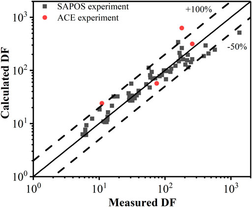
FIGURE 11. Comparison between the calculated DF using the proposed correlation and the experimental DF.
Conclusion
In this study, a small-scale facility for pool scrubbing was built to evaluate the aerosol retention efficiency of the pool. The effects of the operating parameters such as steam mass fraction and submerged depth of the pool scrubbing on the DF were tested systematically. The following conclusions can be drawn from this investigation. Considering the dependence of DF on the steam mass fraction, log(1/(1−Xm)) has a linear relationship with log (DF). The DF varies exponentially with pool depth, and the pool depth has a greater influence on the retention of aerosols for larger particle diameters. For particle diameter in the 0.2–0.52 μm range, it has little effect on the DF. For low–pool-depth scrubbing, the steam condensation mechanism is dominant, and the particle diameter has little effect on the DF. Based on the existing models and the measured DF, a simplified model has been developed to predict the DF, and the error between the measured and calculated DFs is acceptable.
Data Availability Statement
The original contributions presented in this study are included in the article/Supplementary Material; further inquiries can be directed to the corresponding author.
Author Contributions
YL: investigation, formal analysis, and writing–original and draft, review, and editing. LT: methodology, investigation, and writing–review and editing. XC: conceptualization, methodology, and supervision.
Funding
This work was financially supported by the National Science and Technology Major Project in China (2019ZX06004013 and 2017ZX06002003-001-002).
Conflict of Interest
The authors declare that the research was conducted in the absence of any commercial or financial relationships that could be construed as a potential conflict of interest.
Publisher’s Note
All claims expressed in this article are solely those of the authors and do not necessarily represent those of their affiliated organizations, or those of the publisher, the editors and the reviewers. Any product that may be evaluated in this article, or claim that may be made by its manufacturer, is not guaranteed or endorsed by the publisher.
Supplementary Material
The Supplementary Material for this article can be found online at: https://www.frontiersin.org/articles/10.3389/fenrg.2021.675841/full#supplementary-material.
References
Cho, S., Chun, S.-Y., Baek, W.-P., and Kim, Y. (2004). Effect of Multiple Holes on the Performance of Sparger during Direct Contact Condensation of Steam. Exp. Therm. Fluid Sci. 28 (6), 629-638. doi:10.1016/j.expthermflusci.2003.10.002
Dehbi, A., Suckow, D., and Guentay, S. (2001). Aerosol Retention in Low-Subcooling Pools under Realistic Accident Conditions. Nucl. Eng. Des. 203, 229-241. doi:10.1016/S0029-5493(00)00343-5
Escudero Berzal, M., Marcos Crespo, M. J., Swiderska-Kowalczyk, M., Martin Espigares, M., and Lopez Jimenez, J. (1995). State-of-the-art Review on Fission Products Aerosol Pool Scrubbing under Severe Accident Conditions. Luxembourg, Belgium: Report EUR-16241-EN.
Fuchs, N. A. (1964). The Mechanics of Aerosols. New York, NY, USA: Permagon. doi:10.1007/978-3-476-99958-0
Gao, S., Fu, Y., Sun, D., Mei, Q., Pan, N., Zhang, S., et al. (2017). “Comparison Research on Different Aerosol Pool Scrubbing Models,” in Proceedings of the 2017 25th International Conference on Nuclear Engineering. Shanghai, China: Nuclear Engineering Division. doi:10.1115/ICONE25-66540
Hong, S. J., Park, G. C., Cho, S., and Song, C.-H. (2012). Condensation Dynamics of Submerged Steam Jet in Subcooled Water. Int. J. Multiphase Flow 39, 66-77. doi:10.1016/j.ijmultiphaseflow.2011.10.007
Huang, G. F., Tong, L. L., Li, J. X., and Cao, X. W. (2010). Study on Mitigation of In-Vessel Release of Fission Products in Severe Accidents of PWR. Nucl. Eng. Des. 240, 3888-3897. doi:10.1016/j.nucengdes.2010.08.010
Kaneko, I., Fukasawa, M., Naito, M., Miyata, K., and Matsumoto, M. (1992). “Experiment Study on Aerosol Removal Effect by Pool Scrubbing,” in 22nd DOE/NRC Nuclear Air Cleaning and Treatment Conference, Denver Colorado: NUREG/CP-0130. CONF-9020823.
Marcos, C., Gomez, M., Melches, S., Martin Espigares, M., and Lopez Jimenez, J. (1994). Lace-Espana Experimental Programme on the Retention of Aerosols in Water Pools. Spain: CIEMAT.
Moffat, R. J. (1988). Describing the Uncertainties in Experimental Results. Exp. Therm. Fluid Sci. 1 (1), 3-17. doi:10.1016/0894-1777(88)90043-X
Owczarski, P. C., and Burk, K. W. (1991). SPARC-90: A Code for Calculating Fission Product Capture in Suppression Pools. Richland, WA, USA: Pacific Northwest Laboratory. doi:10.2172/6120360
Owczarski, P. C., Scherck, R. I., and Postma, A. K. (1985). Technical Bases and User's Manual for the Prototype of a Suppression Pool Aerosol Removal Code (SPARC). Nucl. Regul. Comm. doi:10.2172/5797428
Park, C. K., Song, C. H., and Jun, H. G. (2007). Experimental Investigation of the Steam Condensation Phenomena Due to a Multi-Hole Sparger. J. Nucl. Sci. Tech. 44 (4), 548–557. doi:10.1080/18811248.2007.9711844
Ramsdale, S., Friederichs, H. G., and Güntay, S. (1991). BUSCA JUN91: Reference Manual for the Calculation of Radionuclide Scrubbing in Water Pools. Koeln, DE: Gesellschaft fuer Anlagen and Reaktorsicherheit mbH (GRS). 3923875665.
Sun, H., Sibamoto, Y., Okagaki, Y., and Yonomoto, T. (2019). Experimental Investigation of Decontamination Factor Dependence on Aerosol Concentration in Pool Scrubbing. Sci. Tech. Nucl. Installations 2019, 1-15. doi:10.1155/2019/1743982
Keywords: aerosol retention, pool scrubbing, decontamination factor, influence factors, scrubbing model
Citation: Li Y, Tong L and Cao X (2021) Experimental Study on Influencing Factors of Aerosol Retention by Pool Scrubbing. Front. Energy Res. 9:675841. doi: 10.3389/fenrg.2021.675841
Received: 04 March 2021; Accepted: 30 June 2021;
Published: 03 August 2021.
Edited by:
Zhaoming Meng, Harbin Engineering University, ChinaReviewed by:
Hui Liang, The University of Tokyo, JapanMei Qiliang, Shanghai Nuclear Engineering Research and Design Institute, China
Copyright © 2021 Li, Tong and Cao. This is an open-access article distributed under the terms of the Creative Commons Attribution License (CC BY). The use, distribution or reproduction in other forums is permitted, provided the original author(s) and the copyright owner(s) are credited and that the original publication in this journal is cited, in accordance with accepted academic practice. No use, distribution or reproduction is permitted which does not comply with these terms.
*Correspondence: Xuewu Cao, Y2FveHVld3VAc2p0dS5lZHUuY24=
 Yuxiang Li
 Lili Tong