 Yinfeng Sun
 Xin Xiong1
 Guoqing Li
 Xueguang Wu
95% of researchers rate our articles as excellent or good
Learn more about the work of our research integrity team to safeguard the quality of each article we publish.
Find out more
BRIEF RESEARCH REPORT article
Front. Energy Res. , 04 August 2021
Sec. Smart Grids
Volume 9 - 2021 | https://doi.org/10.3389/fenrg.2021.672999
This article is part of the Research Topic New Solutions for Smart Grids with High-Penetration Distributed Energy Resources View all 19 articles
Flexible direct current (DC) grid can realize large-scale renewable energy, wide-area coordinated complementation, and reliable power transmission. It is an important development that can be used to support high-voltage and large-capacity flexible DC transmission in the future. The short-circuit current of the DC line is one of the important bases for the selection of key main equipment parameters such as converter valves, DC circuit breakers, and reactors in the flexible DC grid. In this paper, a flexible DC grid equivalent circuit network model with alternating current (AC) feed-in is established. Aiming at the monopolar ground fault of the flexible DC grid grounded through the metal loop, an optimized traditional matrix calculation method is proposed to obtain the accurate line fault current value. On this basis, with an actual engineering background, the equivalent circuit model of the four-terminal bipolar flexible DC power grid is established, and the influence of grounding position, grounding parameters, and current-limiting reactor on the fault current of the DC line is analyzed. Finally, simulation using the PSCAD software verifies the effectiveness and accuracy of the proposed method. The method proposed in this paper can provide the necessary bases and references for the selection of flexible DC grid equipment.
The many advantages of voltage source converter-high-voltage, direct current (VSC-HVDC) make it suitable for new large-scale energy grid connection, grid interconnection (Allebrod et al., 2008; Perez et al., 2015; Guo et al., 2017; Li et al., 2021) and power quality control (Li et al., 2016), DC grid power flow control (Li et al., 2018), and other aspects. With the development of modular multilevel converter (MMC) in the direction of high-voltage, large-capacity, and long-distance power transmission, the use of overhead power transmission with obvious economic and technical advantages has become an inevitable choice. For flexible DC grids with overhead lines, the calculation and the protection of fault currents for DC lines have become an important research concern. Compared with the alternating current (AC) transmission system, the DC transmission system has a lower damping coefficient and response time constant. Therefore, it is hard to imagine that once a DC fault occurs, the fault current will rise fast and have a large amplitude, which will seriously affect the safety and stability of the equipment and even the whole system (Franck, 2011; Liu et al., 2017). At present, the topological structure of half-bridge converters is mostly used in engineering, and the DC circuit breaker is used to remove the fault before converter station blocking, so as to reduce the adverse impact caused by converter station blocking, control the capacity, and reduce the cost. From the point of view of design, in order to verify the braking ability of the DC circuit breaker, it is necessary to accurately calculate the short-circuit current of the lines before the blocking of the converter station.
On the basis of the DC system, Shuai et al. carried out equivalent calculations for the capacitor discharge of the faulty module in a bipolar short-circuit fault and obtained some useful conclusions (Li et al., 2017). On the basis of the double-ended flexible DC system, they took into account the influence of the AC-side feed and converter control. Weiru et al. adopt the recursive equation method to calculate the short-circuit current from the perspective of the converter energy, making the calculation results of short-circuit current more accurate (Wang et al., 2019). However, the shortcoming of this method is that it tends to qualitative analysis and does not consider the fault current calculation in multi-terminal flexible DC grid scenarios. Using a general method for calculating short-circuit current of a DC grid, Li et al. constructed a bipolar flexible DC grid equivalent circuit network (Li et al., 2017). By establishing the initial matrix equations of the flexible DC grid before the fault and the modified matrix equations of the flexible DC grid after the fault, the transient characteristics of the short-circuit current of the flexible DC grid under different operating conditions are quantitatively analyzed. However, the shortcoming of this method is that only the bipolar short-circuit fault is considered and the influence of the AC grid is not involved. On the basis of the flexible DC power grid, the system model after the short-circuit fault was simplified in Tang and Dong (2019). However, the shortcoming of this method is that the influence of the AC feed is ignored. To sum up, in the current academic research on DC fault current, only a few researchers take the influence of the AC system into account; even if considered, there is no clear analytical expression. However, it is undeniable that this neglect and approximation will inevitably produce certain errors, which is not conducive to the accurate selection, precise control, and setting calculation of the DC equipment. The method of considering the influence of the AC feed into the calculation of DC short-circuit current cannot obtain the accurate analytical expression of DC short-circuit current, and the research on the quantitative analysis of the influence of injected power of the converter on fault current before DC grid failure is still blank. When volatile large-scale wind power, photovoltaic power, and other renewable energy sources are connected to the flexible DC grid, especially when the renewable energy adopts low voltage ride-through or fault ride-through strategies, fault current may be continuously fed to the fault point under the fault condition. Because of the higher probability of monopolar ground faults and the need for the influence of the grounding method to be considered, the calculation is more complicated. Therefore, this article focuses on a detailed and in-depth analysis of the grounding method through metal loops and monopolar ground faults used in actual projects.
A mathematical model of the MMC converter considering AC feed is established firstly on the basis of traditional AC and DC equivalent channels. The AC feed as a controlled DC source is incorporated into the calculation of DC capacitance and discharge, and the analysis method of single-pole grounding fault of metal loop grounding flexible DC network is improved. At the same time, the equivalent circuit model of bipolar flexible DC network is constructed. Secondly, the initial matrix equations of the flexible DC grid before the failure are established, and the initial matrix equations before the failure are revised twice to obtain the fault current correction matrix equations of the flexible DC grid after the failure. Finally, a simulation analysis of a typical example is performed to verify the correctness and effectiveness of the proposed method.
When a pole bus or a converter fails in a bipolar symmetrical system structure, it only affects the fault pole and the converter connected with the fault pole and has little effect on the other pole, so as to effectively improve the reliability and safety of the system operation. This paper takes the positive electrode short-circuit fault as an example to illustrate. The detailed topology of an MMC converter station positive pole is shown in Figure 1.
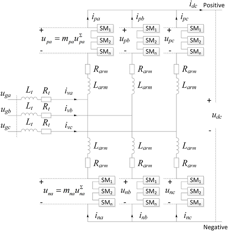
Figure 1. Detailed topology of an MMC converter station positive pole.
In Figure 1, the voltage and current of each bridge arm are, respectively, denoted as urj and irj (subscript r = p, n, respectively, represent the upper and lower bridge arms; subscript j = a, b, c, respectively, represent the three phases, namely, a, b, and c, similarly hereinafter). In addition, mrj and uΣ rj represent the modulation signal and voltage of each bridge arm, respectively. ivj represents the output AC current of the MMC. ugj represents the voltage at the PCC point of the AC grid. Lt and Rt represent the leakage inductance and resistance of the connected transformer, respectively, while Udc and idc represent the DC positive voltage and DC current, respectively. As shown in the figure, the directions of all electrical quantities are marked.
Under the condition of system equilibrium, according to the Kirchhoff Voltage Law (KVL), the voltage equations of the upper and lower bridge arms in a single-phase circuit can be obtained as follows (Harnefors et al., 2013):
The input ratios of the sub-modules in the upper and lower bridge arms of MMC are, respectively,
where M is the modulation ratio; ωg is the fundamental angular frequency; ϕj is the initial phase.
According to the current-voltage relationship in Figure 1,
where uvj represents the output voltage of phase j of the MMC, also known as the internal potential of the MMC; ucomj is defined as the common-mode voltage of the upper and lower arms of phase j; and icirj represents the circulating current of phase j.
The mathematical equation of the dynamic characteristics of the equivalent circuit of the DC side of the MMC can be obtained by subtracting the Equation (1) as
First, the three-phase superposition on the DC side dynamic Equation (4) of MMC is performed to obtain
In addition, as can be seen from the figure the relation between the sum of the three-phase circulation and the DC current is
The equivalent capacitor voltage uce of the MMC is defined as
Equation (6) and (7) are then substituted into Equation (5). Then, the equivalent circuit model of the DC side of the MMC can be initially obtained:
The following two pairs of equations are introduced here to further establish a DC equivalent model taking into account the AC effects:
The above equation describes the internal relationship between the output voltage of the bridge arm of the MMC and the sum of the capacitive voltages of all the sub-modules of the bridge arm (Harnefors et al., 2013).
Assuming that the capacitor voltages of the sub-modules are completely balanced, uΣ pj ≈ uΣ nj; Equations (2), (3), and (9) are combined to obtain
Upon substitution of Equation (11) back into Equation (7), expressing the equivalent capacitance voltage uce of MMC,
Derivation of the above equation and combination with Equation (10) can be obtained
Further, Equation (2) is substituted into the above equation for simplification. The obtained equation contains a more intuitive physical meaning.
At this time, Ce = 6C0/N is defined as the equivalent capacitance of MMC; C0 represents the capacitance value of the converter sub-module; Pcon represents the injected power of the converter station; idcs represents the controlled DC current source of the equivalent circuit of the DC side of the MMC.
According to Equation (14), the controlled DC current source can be calculated as
In the steady-state operation of the system, the charge and discharge of the MMC capacitor maintain a dynamic balance, and the capacitor voltage fluctuation is relatively small, which causes the capacitor current ice to be approximately zero, that is
By combining Equations (14) and (16), the following can be obtained:
where pdc represents the active power on the DC side of the converter station, while udc represents the voltage between the DC poles.
At the same time, due to the minimal resistance of the MMC bridge arm, the internal loss of the MMC can be ignored. According to the power balance principle of the AC and DC sides, the following can be obtained:
The theoretical analysis result of Equation (18) is the same as the mathematical deduction result of Equation (17), which verifies the correctness of the formula of the controlled DC current source.
A four-terminal DC equivalent circuit network model is provided in Figure 2, where Le represents the equivalent inductance of the discharge circuit, while Re represents the equivalent resistance of the discharge circuit; n1, n2, n3, and n4 represent the positive node of the converter station, n1', n2', n3,' and n4' represent the negative node of the converter station, and n10-n20-n30-n40 represent the metal loop. The equivalent capacitance voltage matrix of the converter station of the flexible DC grid can be obtained by listing the KVL equations among the various discharge circuits:
where U = [uc1,uc2,uc3,uc4]T represents the equivalent capacitance voltage matrix of the converter station; I0 = [i12,i23,i34,i41]T represents the line current matrix between the stations; A0 represents the initial correlation matrix; R0 represents the initial resistance matrix; and L0 represents the initial inductance matrix. The parameters A0, R0, and L0 can be represented in the matrix as follows:
where Rei and Lei represent the equivalent resistance and equivalent inductance of the i converter and Rij and Lij represent the line resistance and the line inductance between the i and j converters.
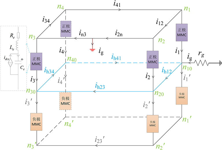
Figure 2. A four-terminal DC equivalent circuit network model.
The relationship between equivalent capacitance current and DC line current in the converter station is as follows:
where Ic= [ic1,ic2,ic3,ic4]T represents the equivalent capacitance current matrix of the converter station, while Idcs= [iac1,iac2,iac3,iac4]T represents the equivalent AC feed current matrix of the converter station.
The relationship between the equivalent capacitance voltage matrix of each converter station and the line current matrix is given as
The C matrix is defined as
Substituting Equation (15) into the above equation yields
where U−1 represents the matrix of the reciprocal of the capacitor voltage of each converter station, i.e., U−1 = [1/uc1,1/uc2,1/uc3,1/uc4]T; P0 represents the initial output power of each converter station matrix, and the parameters are as follows:
The initial matrix equations of the flexible DC grid are
Assuming that the short-circuit fault occurs on the branch bij, the distance between the fault location and the node ni, denoted by x, accounts for the percentage of the total length of the faulted line. After a fault, the flexible DC grid will add a node, n0, and the number of branches will increase by one, accordingly. The branch resistance matrix R and the inductance matrix L are increased by one row and one column, respectively; the branch resistance rij is updated to ri0 and r0j, and the branch inductance Lij is updated to Li0 and L0j, as shown in Equation (27).
The branch current iij is corrected to ii0 and i0j, and the line current matrix between stations I0 = [···,iij, ···]T is corrected to It = [···,ii0,i0j, ···]T. The U dimension of the equivalent capacitance voltage matrix of the flow station remains unchanged. Correspondingly, one row is added to the initial incidence matrix A0.
The corrected equivalent capacitance voltage matrix of the converter station in the flexible DC grid is expressed as
If the metal loop is included in the fault circuit, the voltage drop of the metal loop needs to be taken into account, and the correction equation becomes
where B is the incidence matrix with a size of 5 × 4; bki = 1 is the kth loop that passes through the metal loop; bki = 0 is the kth loop that does not pass through the metal loop. Rh is the resistance matrix of each branch of the metal return line, which has a size of 4 × 4; Ih represents the current matrix of each branch of the metal return line, i.e., Ih = [ih12,ih23,ih34,ih41]T. The parameters of B and Rh are as follows:
As shown in Figure 2, by listing the KCL relation of n-1 neutral points and the KVL relation of the metal return line, it can be concluded that
The matrix expression of the metal loop current can be obtained from the above equation
where R1 is the resistance matrix of size 4 × 5; R2 is the resistance matrix of size 4 × 4; and In0 is the current matrix of each converter station of sound pole, i.e., In0 = [i10,i20,i30,i40]T
The equivalent capacitance voltage matrix equation of the converter station of the flexible DC grid can be obtained by substituting Equation (32) into Equation (29). By combining the line current matrix equation obtained before, the current of each line and the capacitor voltage of each converter station can be obtained, as given in the equation below.
The model parameters correlate to the Zhangbei DC project in China as follows: rated DC voltage is ±500 kV, rated DC current is 3 kA, rated power are 1,500/3,000/3,000/1,500 MW, sub-module capacitances are 8/15/15/11.2 mF, bridge arm inductances are 100/50/50/100 mH, the inductance of the DC bus smoothing reactor is 150 mH, and the inductance of the neutral smoothing reactor is 300 mH.
As shown in Figure 3, the calculation results of DC fault current not considering the influence of AC-side feed and the calculation results of DC fault current taking into account the influence of AC-side feed are compared and analyzed in this paper.
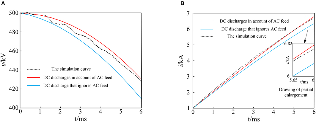
Figure 3. DC capacitor voltage and DC fault current during monopolar ground fault. (A) Sub-module capacitance voltage. (B) DC fault current.
As shown in Figure 3, the difference between the DC discharge voltage which does not consider the influence of AC feed and the DC discharge voltage which takes the influence of AC feed into account is 20.20 kV, accounting for 4.04% of the rated voltage of the converter station. Meanwhile, the difference between the DC discharge current, not taking into account the influence of the AC feed, and the DC discharge current considering the influence of the AC feed is 547.8 A, which accounts for 8.12% of the line fault current. The results show that the capacitor voltage and the fault current curves of the sub-module while considering the AC influence are more consistent with the simulation curves.
As shown in Figure 4, a monopolar ground fault at the midpoint of the DC lines of converter station 2 and converter station 3 should be set, and the transient current waveforms of each DC line within 6 ms after the fault should be recorded. As shown in Figure 4, the line current calculation waveform of the improved method, the line current simulation waveform with the AC feed, and the line current simulation waveform without the AC feed are presented. The AC feed line current simulation waveform should be ignored and the circuit breaker should be set on the AC side. When the fault occurs, the AC circuit breaker acts to remove the influence of the AC feed on the fault line current. The dotted line is the simulation current of the line on both sides of the fault point, ignoring the AC feed. Figure 4 shows that, the results obtained by the improved method in this paper are in good agreement with the simulation results, and the error of 6 ms current accounts for 0.6% of the fault current, which verifies the rationality and accuracy of the improved method. In addition ,it can be seen that, compared with the calculated value and simulation value of fault current considering the influence of AC feed, the error of ignoring AC feed is about 300A, accounting for about 6% of the peak fault current.
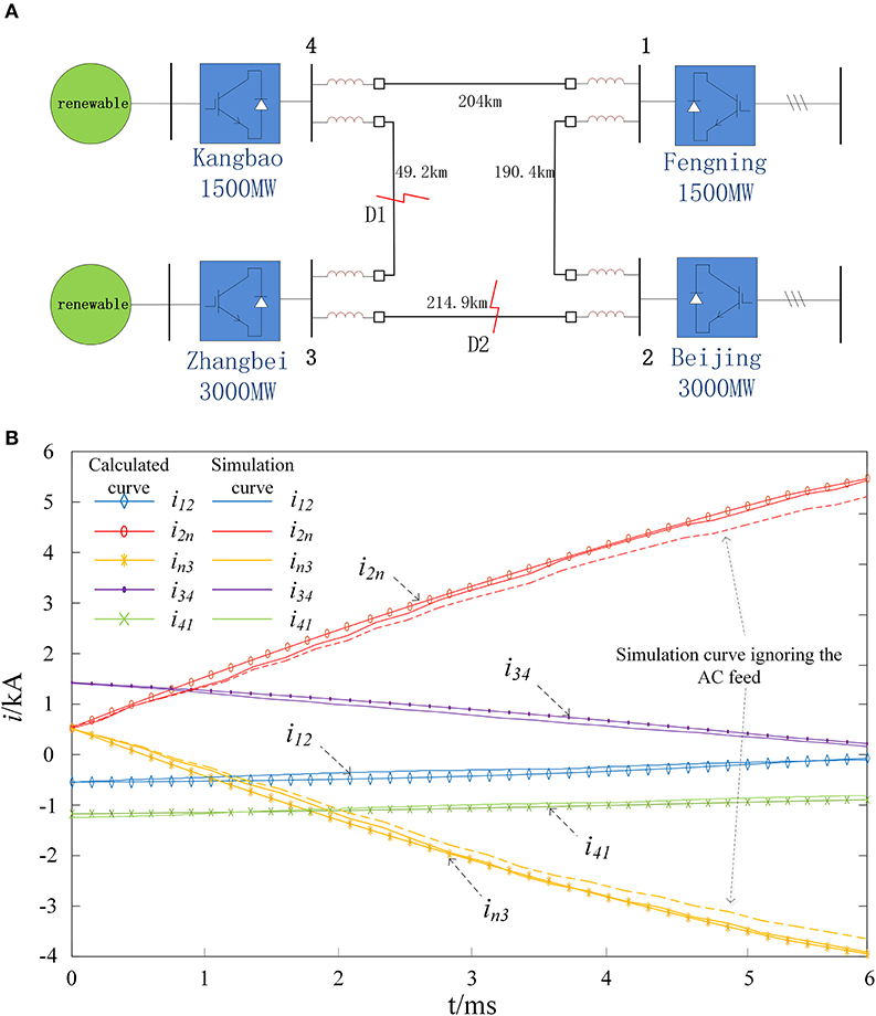
Figure 4. Analysis of DC fault current in MMC flexible DC grid. (A) Four- terminal DC power grid topology. (B) DC line current during the monopolar ground fault.
In this paper, research on an improved fault current analysis method of the DC grid with the AC feed taken into account is proposed, and the effectiveness of the method is verified by applying the method to an actual project. The main work performed on this paper and conclusions are summarized as follows:
1. The mathematical model of the DC discharge equivalent circuit with the inclusion of the AC feed is established, and the current source on the AC side of the model is equivalent.
2. The results obtained by the improved method in this paper are in good agreement with the simulation results, which not only verifies the influence of the AC feed on the fault current of the DC line but also proves the rationality of the improved method.
3. As can be seen, omitting the influence of the AC feed will reduce the calculation accuracy of the DC line short-circuit current, which will inevitably affect the accuracy of the DC grid equipment selection and control parameter setting.
To sum up, the fault current analysis method of a flexible DC grid proposed in this paper can be used to provide necessary bases and references for the equipment selection and the parameter setting of a flexible DC grid.
With the further-increasing new energy capacity access to the DC grid, its volatility and uncertainty can easily lead to a wide range of fluctuations in AC feed power and DC power flow, and the resulting changes in the DC fault current cannot be ignored, especially when considering the large-scale off-grid or grid-connected conditions of wind power, photovoltaic power, etc. Of course, at this time, the adaptability of the method in this paper should be discussed in depth based on the respective fault crossing strategies of power supply and DC grid, which is also the research topic that the authors are carrying out at present.
The original contributions presented in the study are included in the article/supplementary material, further inquiries can be directed to the corresponding author/s.
YS, ZW, and GL contributed to conception and design of the study. XX organized the database. YS and XW performed the statistical analysis. YS wrote the first draft of the manuscript. YS, XX, XW, and WW wrote sections of the manuscript. All authors contributed to manuscript revision, read, and approved the submitted version.
This work was supported by the National Key R&D Program of China (No. 2018YFB0904600), Jilin Provincial Department of Education Research Project (JJKH20190704KJ), and Key Project of Jilin Science and Technology Bureau (2019301163).
The authors declare that the research was conducted in the absence of any commercial or financial relationships that could be construed as a potential conflict of interest.
All claims expressed in this article are solely those of the authors and do not necessarily represent those of their affiliated organizations, or those of the publisher, the editors and the reviewers. Any product that may be evaluated in this article, or claim that may be made by its manufacturer, is not guaranteed or endorsed by the publisher.
Allebrod, S., Hamerski, R., and Marquardt, R. (2008). New Transformerless,Scalable Modular Multilevel Converters for HVDC-Transmission[C]//Power Electronics Specialists Conference(PESC) (Rhodes: Institute of Electrical and Electronics Engineers), 174–179. doi: 10.1109/PESC.2008.4591920
Franck, C. M. (2011). HVDC circuit breakers: a review identifying future research needs. IEEE Trans. Power Delivery 26, 998–1007. doi: 10.1109/TPWRD.2010.2095889
Guo, C., Liu, W., Zhao, C., and Iravani, R. (2017). A frequency-based synchronization approach for the VSC-HVDC station connected to a weak AC grid. IEEE Trans. Power Delivery 32, 1460–1470. doi: 10.1109/TPWRD.2016.2606495
Harnefors, L., Antonopoulos, A., Norrga, S., Angquist, L., and Nee, H.-P. (2013). Dynamic analysis of modular multilevel converters. IEEE Trans. Indust. Electron. 60, 2526–2537. doi: 10.1109/TIE.2012.2194974
Li, B., Zhou, S., Xu, D., Yang, R., Xu, D., Buccella, C., et al. (2016). An improved circulating current injection method for modular multilevel converters in variable-speed drives. IEEE Trans. Indust. Electron. 63, 7215–7225. doi: 10.1109/TIE.2016.2547899
Li, C., Zhao, C., Xu, J., Ji, Y., Zhang, F., and An, T. (2017). A pole-to-pole short-circuit fault current calculation method for DC grids. IEEE Trans. Power Syst. 32, 4943–4953. doi: 10.1109/TPWR.S.2017.2682110
Li, S., Guo, C., Zhao, C., and Xu, J. (2017). A novel MMC topology with lower power loss and DC fault ride-through capability. Proce. CSEE 37, 1–9. doi: 10.13334/j.0258-8013.pcsee.162109
Li, Y., Li, Y., Li, G., Zhoa, D., and Chen, C. (2018). Two-stage multi-objective OPF for AC/DC grids with VSC-HVDC: incorporating decisions analysis into optimization process. Energy 147, 286–296. doi: 10.1016/j.energy.2018.01.036
Li, Y., Wang, C., Li, G., and Chen, C. (2021). Optimal scheduling of integrated demand response-enabled integrated energy systems with uncertain renewable generations: a Stackelberg game approach. Energy Conver. Manage. 235:113996. doi: 10.1016/j.enconman.2021.113996
Liu, G., Xu, F., Xu, Z., Zhang, Z., and Tang, G. (2017). Assembly HVDC breaker for HVDC grids with modular multilevel converters. IEEE Trans. Indust. Electron. 32, 931–941. doi: 10.1109/TPEL.2016.2540808
Perez, M. A., Bernet, S., Rodriguez, J., Kouro, S., and Lizana, R. (2015). Circuit topologies,modeling,control schemes,and applications of modular multilevel converters. IEEE Trans. Indust. Electron. 30, 4–17. doi: 10.1109/TPEL.2014.2310127
Tang, L., and Dong, X. (2019). An approximate method for the calculation of transmission line fault current in MMC-HVDC grid. Proc. Chin. Soc. Electr. Eng. 39:181327. doi: 10.13334/j.0258-8013.pcsee.181327
Keywords: flexible DC grid, short-circuit current, AC feed, monopolar ground fault, matrix calculation
Citation: Sun Y, Xiong X, Wang Z, Li G, Wu X and Wang W (2021) Research on Improved Fault Current Analysis Method for Flexible Direct Current Power Grid Considering Alternating Current Feed. Front. Energy Res. 9:672999. doi: 10.3389/fenrg.2021.672999
Received: 26 February 2021; Accepted: 15 March 2021;
Published: 04 August 2021.
Edited by:
Liang Chen, Nanjing University of Information Science and Technology, ChinaReviewed by:
Shaoyan Li, North China Electric Power University, ChinaCopyright © 2021 Sun, Xiong, Wang, Li, Wu and Wang. This is an open-access article distributed under the terms of the Creative Commons Attribution License (CC BY). The use, distribution or reproduction in other forums is permitted, provided the original author(s) and the copyright owner(s) are credited and that the original publication in this journal is cited, in accordance with accepted academic practice. No use, distribution or reproduction is permitted which does not comply with these terms.
*Correspondence: Yinfeng Sun, MjczNTI0MDgzQHFxLmNvbQ==
Disclaimer: All claims expressed in this article are solely those of the authors and do not necessarily represent those of their affiliated organizations, or those of the publisher, the editors and the reviewers. Any product that may be evaluated in this article or claim that may be made by its manufacturer is not guaranteed or endorsed by the publisher.
Research integrity at Frontiers
Learn more about the work of our research integrity team to safeguard the quality of each article we publish.