 Kenneth E. Okedu
 Hind Barghash
95% of researchers rate our articles as excellent or good
Learn more about the work of our research integrity team to safeguard the quality of each article we publish.
Find out more
ORIGINAL RESEARCH article
Front. Energy Res. , 21 April 2021
Sec. Smart Grids
Volume 9 - 2021 | https://doi.org/10.3389/fenrg.2021.655051
This article is part of the Research Topic Grid Connection of Converters in Renewable Applications View all 9 articles
One of the ways of generating electrical power from wind energy is by employing the promising technology of the permanent magnet synchronous generator (PMSG) variable speed wind turbine (VSWT). With the daily increase and integration of wind farms into traditional power grids, it is imperative to carry out transient stability studies of wind generators in wind farms, in order to fulfill the operational grid codes. To solve the transient stability intricacies posed by the stochastic nature of wind energy during transient states or grid faults, this paper presents the enhancement of PMSG wind turbine considering the excitation parameters of the insulated gate bipolar transistors (IGBTs) of the wind generator. The investigation was carried out using the turn on and turn off resistances of the IGBTs of the power converters of the PMSG wind turbine, considering different scenarios, with and without over voltage protection scheme. A severe three-line-to-ground fault was used to test the robustness and rigidity of the controllers of the wind generator during transient state. Furthermore, the results obtained using the PMSG wind turbine were compared to those using the doubly fed induction generator (DFIG) wind turbine. The evaluation of the system performance was done using the power system computer “aided” design and electromagnetic transient including DC (PSCAD/EMTDC) platform. The same conditions of operation were used in investigating the various scenarios considered in this study.
Based on the recent emerging grid requirements, wind farms are expected to have good performance under grid fault, considering the capability of voltage control. There are bound to be intricacies in operating the power grid smoothly due to grid disturbances. Consequently, it is necessary to proffer solutions using new techniques to overcome this shortcoming considering the complex nature of the control strategies of modern power grids (Singaravel and Daniel, 2015). The topologies of variable speed wind turbine (VSWT) have various generator and converter schemes with regards to capturing of energy, cost, efficiency, and control strategies complexity (Ahmed et al., 2019). The two most commonly used VSWT for wind energy conversion in modern wind farms are the doubly fed induction generator (DFIG) wind turbine and the permanent magnet synchronous generator (PMSG)-based VSWT. Although the earlier wind turbine is more popular, the later wind turbine technology has a more feasible wind generation technology, making it more promising due to its self-excited nature; hence, it is possible to operate higher efficiency and power factor. Besides, the PMSG technology has no gearbox system because of its low rotational speed. Therefore, no careful and regular maintenance is required in this wind turbine topology, unlike the DFIG-based wind turbine (Okedu et al., 2011). More so, the PMSG wind turbine power converters have room for flexible control of active and reactive power dissipation during transient conditions (Michalke et al., 2007; Rosyadi et al., 2012). This type of wind turbine technology has a full-rated back-to-back power converter tied to the grid. As a result, compared to the earlier wind turbine topology, the flexibility in the later type of wind turbine is maximum, making the control of real and reactive power more effective. However, some challenges of the PMSG wind turbine are high cost and construction and control strategy complexities.
In the literature, there are many reports on the control strategies and fault ride through topologies concerning PMSG wind turbines. Nasiri and Mohammadi (2017) enhanced the PMSG wind turbine considering its peak current limitation, while a control strategy based on the maximum power point tracking (MPPT) for both power converters was used (Gencer, 2018). Superconducting fault current limiter (SFCL) was used in Yehia et al. (2018) to improve the performance of the PMSG wind turbine during grid fault. The use of expensive static synchronous compensator (STATCOM) in Zeng et al. (2016) and DC braking chopper fault ride-through (FRT) solution in Alepuz et al. (2013); Ghatikar et al. (2016), and Hossain (2017) are some of the most common control strategies employed in enhancing the performance of the PMSG wind turbine during transient state.
Furthermore, soft computing techniques have been extended to the PMSG wind turbine control topology. In Pulido et al. (2018), the fuzzy logic controller was employed for the PMSG, with some benefits over conventional controllers of the wind generator. The drawback of this computing scheme is the architecture and low sensitivity level to parameters variation. A combined approach of using conventional proportional integral derivative (PID) controllers with the soft computing scheme of fuzzy logic was carried out in Rosyadi et al. (2012), for improved performance of the PMSG wind generator. Some more complex soft computing techniques were extended for the PMSG wind turbine by implementing linear observer extended state in Youjie et al. (2019) and fuzzy adaptive strategy in Mahmoud et al. (2019), respectively.
A dynamic voltage restorer was used to improve the performance of the PMSG wind generator in Jerin et al. (2017). In the literature, an SFCL that is modified considering flux coupling was used to enhance the FRT performance of the PMSG wind turbine. The principle and theoretical influence of the modified SFCL structure on the PMSG ride through capability were conducted, and a comparison of the SFCL with a dynamic braking chopper was performed in Chen et al. (2017). In Moghadasi et al. (2016), a resistive SFCL was employed as an additional self-healing mechanism to support large wind power plant in order to enhance the rated active power of the PMSG wind turbine. The scheme was also able to improve the DC-link voltage smoothness and the low voltage ride-through (LVRT) capability of the wind generator. A cooperative strategy that is integrated with a cost-effective superconducting magnetic energy storage (SMES) unit, considering two modified wind turbine generator control strategies, was presented in Huang et al. (2019). In that paper, the effective utilization of SMES system was achieved during grid faults based on the over voltage suppressing effect in the DC link of the wind generator. A new multistep bridge-type fault current limiter (MSBFCL) PMSG FRT enhancement was presented in Firouzi et al. (2020). The multiresistors were connected in parallel with the insulated-gate bipolar transistor (IGBT) switches and were employed to provide a controllable discrete step resistance.
Although these enhancement schemes highlighted above were able to improve the performance of the PMSG wind turbine during transient state, however, they are additional circuitries to the PMSG wind turbines. In this regard, this paper tends to propose a simple and cost-effective FRT solution for the PMSG wind generator. The effects of the excitation parameters of the power converter’s IGBTs of the PMSG wind turbine during transient condition was investigated. The excitation parameters of the IGBTs that were investigated include the turn on and turn off resistances. It has already been reported in Okedu and Barghash (2021) that the forward break over and reverse withstand voltages have no much effects on the transient performance of the variable speed wind generators. An extensive analysis of the effects of the excitation parameters of the IGBTs was carried out by considering three scenarios of the IGBT’s turn on resistances with and without considering DC-chopper braking resistor for over voltage protection of the PMSG wind turbine. The IGBT turn on resistance has a significant effect on the responses of the wind generator’s variables, while its turn off resistance has little or minimal effects on the variables of the wind generator. The results obtained using the PMSG wind turbines were compared to those obtained using the DFIG wind turbines. The evaluation of the system performance was carried out using power system computer design and electromagnetic transient including DC (PSCAD/EMTDC).
Figure 1 shows the wind generator characteristics, relating the turbine output power and the rotor speed for varying wind speeds with maximum obtainable power output of 1.0 pu at 1.0 pu rotational speed for the PMSG wind turbine. In this type of wind turbine technology, the reference power Pref is limited to the wind generator rated power. The full back-to-back power converters of the PMSG wind turbine (Li et al., 2017), tied to the grid, are shown in Figure 2. For MPPT realization in this type of wind generator (Lee and Chun, 2019; Priyadarshi et al., 2019), the speed control is achieved by the machine side converter (MSC). However, the grid side converter (GSC) does the effective DC-link voltage stabilization and regulation of the power factor and power quality. The ratings and parameters of the PMSG wind turbine used for this study are given in Table 1.
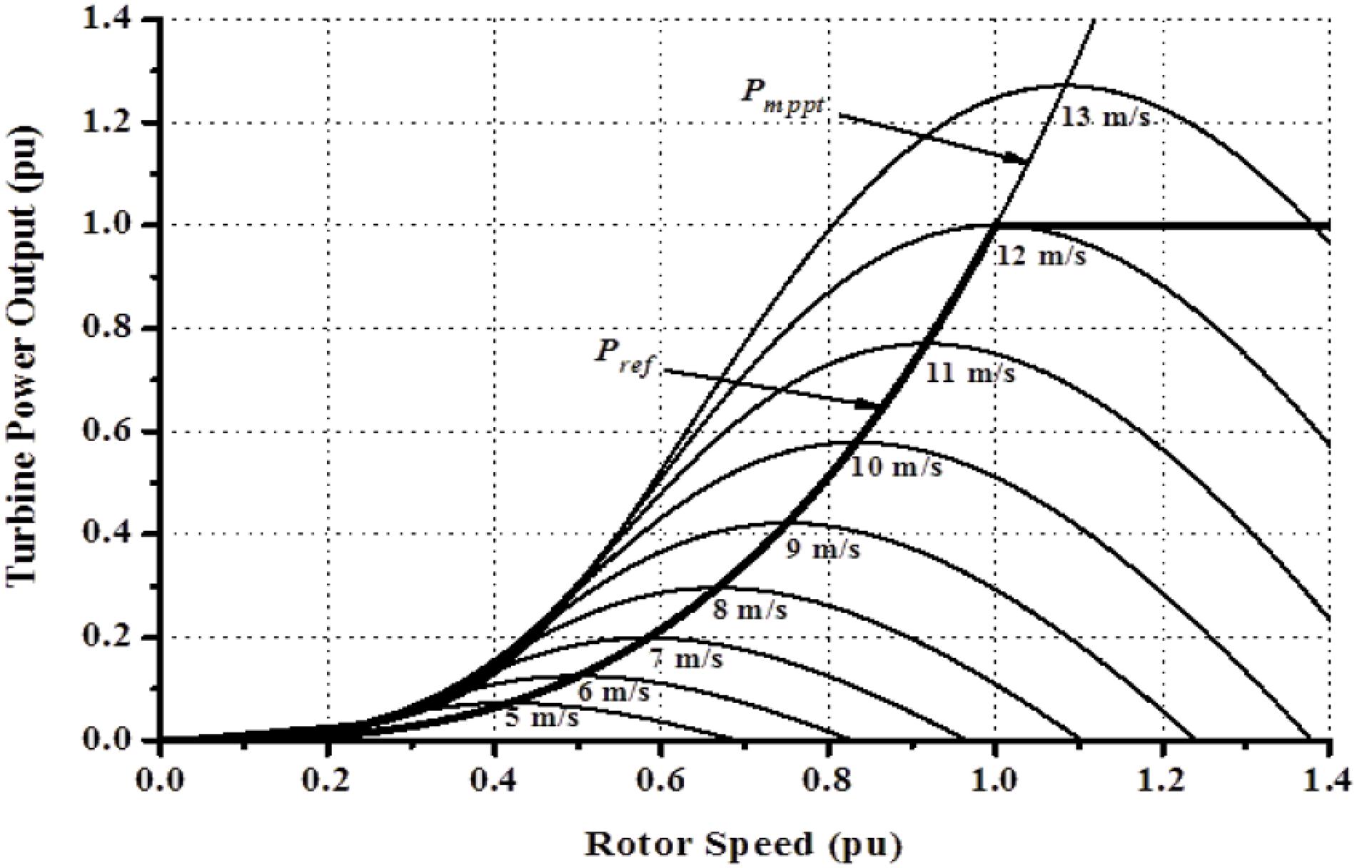
Figure 1. Maximum power characteristics for PMSG wind turbines.
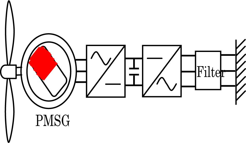
Figure 2. A typical PMSG based wind turbine.
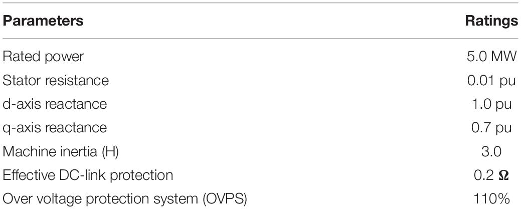
Table 1. Parameters of the PMSG wind turbine.
The mechanical power extracted by the PMSG wind turbine from the wind is expressed as (Okedu et al., 2012):
From Eq. 1, Pw is the wind power that is captured, expressed in (W); the air density is ρ expressed in (kg/m3); the radius R is expressed in (m); and the wind speed Vw is expressed in (m/s). The wind generator’s power coefficient is Cp and is related to the ratio of the tip speed (λ) and angle of the pitch (β), respectively, as expressed in Eq. 2 (Matlab documentation center, 2012).
where
In Eq. 2, c1 to c6 are the characteristic coefficients of the wind turbine. In the PMSG wind turbine, the MPPT is based on the rotor speed and the maximum power could be obtained by Muyeen et al. (2011),:
where λopt is the optimal value of λ, and ωr is the rotor speed of the wind generator. The d–q reference rotating frame for the dynamic model of the PMSG wind turbine is expressed as (Li et al., 2010):
Considering Eqs 5 and 6,
where Vsd and Vsq are the voltages of the stator circuit, Rs is the winding resistance of the stator, Isd and Isq are the currents in the stator d and q reference frames, ωe is the rotational speed of the wind generator, ψsd and ψsq are the flux linkages of the stator circuit, Lsd and Lsq are the stator wind leakage inductances, Lmd and Lmq are the magnetizing inductances, and ψm is the linkage flux of the machine’s permanent magnet. Substituting Eqs 7 and 8 into Eqs 5 and 6, the PMSG differential equations could be obtained as:
The PMSG active and reactive powers are given as:
The wind generator electrical torque with number of pole pairs is given as:
Figure 3A shows the controller of the MSC of the PMSG that regulates both active and reactive powers of the wind turbine. The abc to dq variables transformation is achieved via angle position rotor (θr), considering the rotor speed of the wind generator. The d-axis current (Isd) regulates the active power (Ps), while the q-axis current (Isq) controls the reactive power (Qs) of the wind generator, respectively. The MPPT technique for the characteristic of the wind turbine in Figure 1 is employed in the reference active power (Pref). Usually, the reference reactive power (Qs∗) is fixed at 0 to obtain effective operation of unity power factor. Three reference phase voltages (Vsa∗, Vsb∗, Vsc∗) are generated for the PWM switching through the outputs of the current controller based on the voltage references Vsd∗ and Vsq∗. The GSC control of the wind generator is also shown in Figure 3B and is regulated considering the d–q rotating reference frame based on the grid voltage the same as the speed of rotation. The Park transformation is used in converting (Iga, Igb, Igc) and (Vga, Vgb, Vgc) three-phase voltage and current of the grid into their rotating d–q reference frame. The extraction of the phase angle (θg) of the grid side is done by considering the phase lock loop.
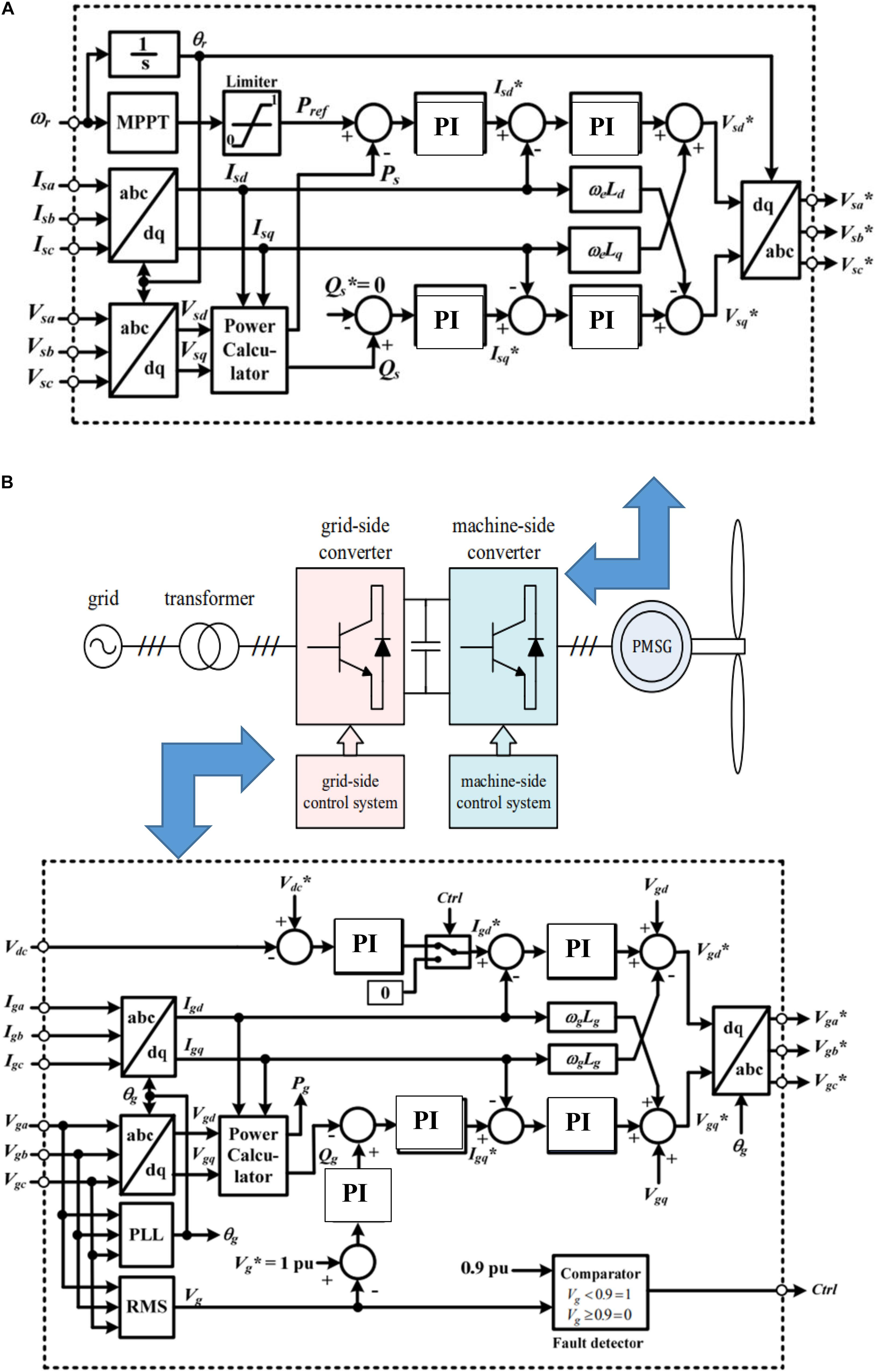
Figure 3. Control strategy of PMSG based wind turbine. (A) Machine side converter control circuit of the PMSG. (B) Grid side converter control circuit of the PMSG.
The schematic diagram of the basic structure and equivalent circuit of an IGBT switch is shown in Figure 4. Table 2 gives the summary of the excitation parameters and their respective ratings, investigated in this study.
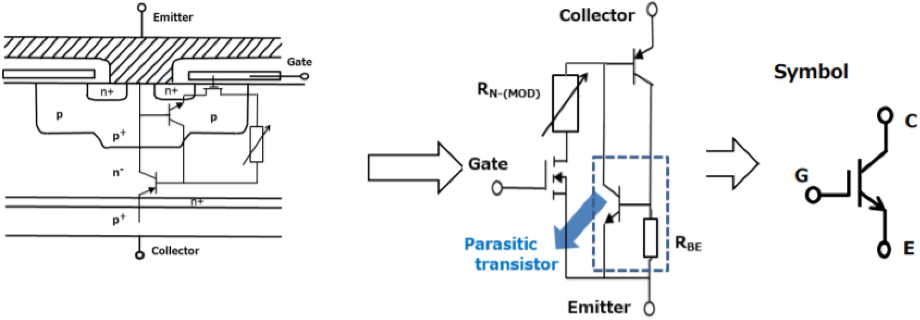
Figure 4. Basic structure and equivalent circuit of IGBT.
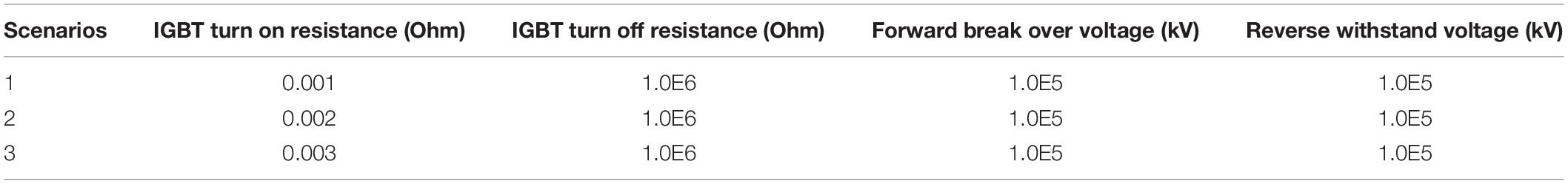
Table 2. Excitation parameters of the insulated gate bipolar transistors.
The operation of the IGBT in Figure 4 is characterized by the conductivity modulation of the n− region in addition to the operation represented by the equivalent circuit. In the IGBT circuit, the holes are the minority carriers and because they are injected into the n− region from the p+−n+ region, conductivity modulation occurs in the n− region. From the equivalent circuit in Figure 4, the saturation voltage [VCE(sat)] of the IGBT can be expressed as (Toshiba Electronic Devices & Storage Corporation., 2018):
From Eq. 16:
VBE is the base-emitter voltage;
ID is the drain current;
RN–(MOD) is the resistance of the n− region after conductivity modulation; and
Rch is the channel resistance.
If the collector current and the DC gain current are IC and hFE, respectively, then, ID is calculated as:
The total current of the IGBT (IIGBT) is:
Equation (16) reflects that the saturation voltage VCE(sat) of an IGBT depends onID, which is a direct function of hFE in Eq. 17. From Eq. 16, increasing the resistance in the n− region would result in conductivity modulation of the IGBT in the PMSG wind turbine.
The ratings of the turn on and turn off resistances and forward break over and reverse withstand voltages excitation parameters of the IGBTs considered in this study for the three scenarios are shown in Table 2. The IGBT turn on resistance has much effect on the responses of the PMSG wind generator’s variables, while its turn off resistance has little or minimal effects on the variables of the wind generator. These would be demonstrated in the simulation results and discussion section of this paper. The forward break over and reverse withstand voltages of the IGBT have no effect on the performance of the wind generator variables during transient conditions. Thus, the variation of the forward break over and reverse withstand voltages of the wind generator power converter does not contribute to the wind turbine enhancement during steady state and grid fault conditions.
The effects of the excitation parameters on the PMSG variable speed wind turbine responses considering a severe bolted three-phase-to-ground fault was investigated in this section based on the different scenarios given in Table 2. Some of the simulation results of the PMSG variables are presented in Figures 5–9.

Figure 5. DC-link voltage of PMSG without OVPS.
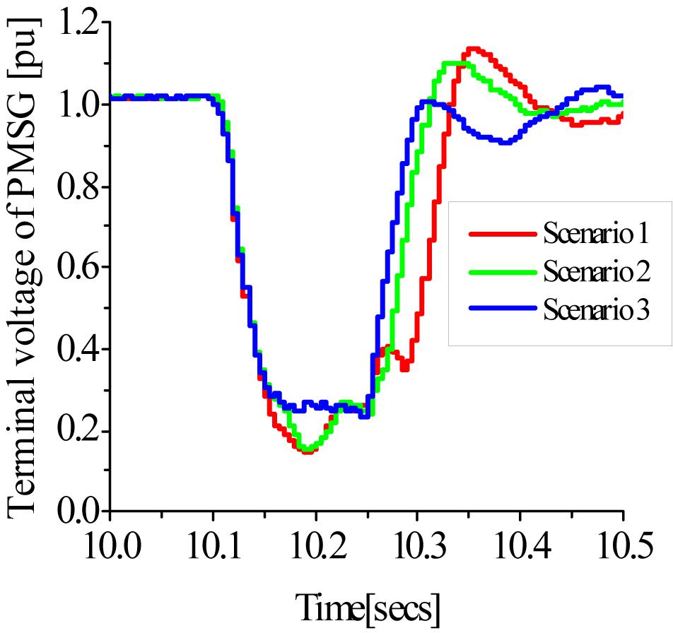
Figure 6. Terminal voltage of PMSG without OVPS.
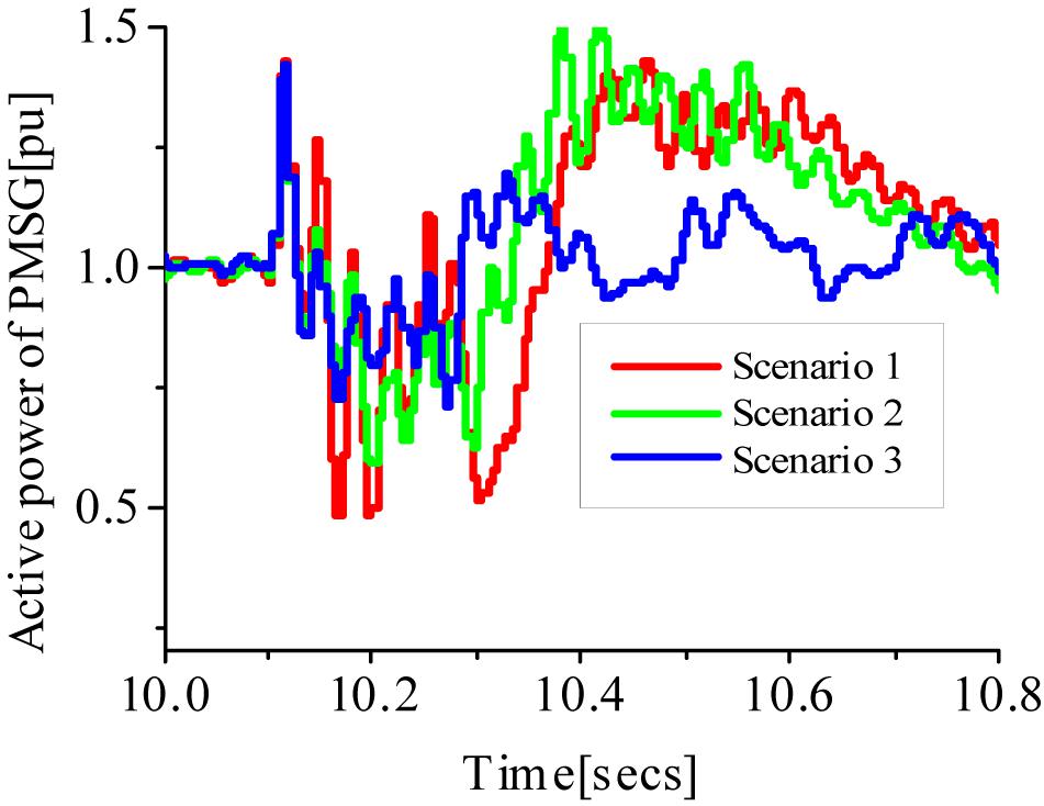
Figure 7. Active power of PMSG without OVPS.
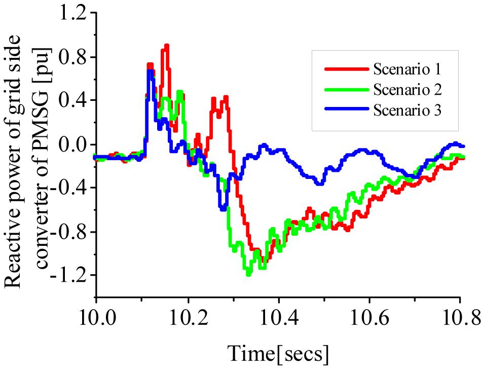
Figure 8. Reactive power of PMSG without OVPS.
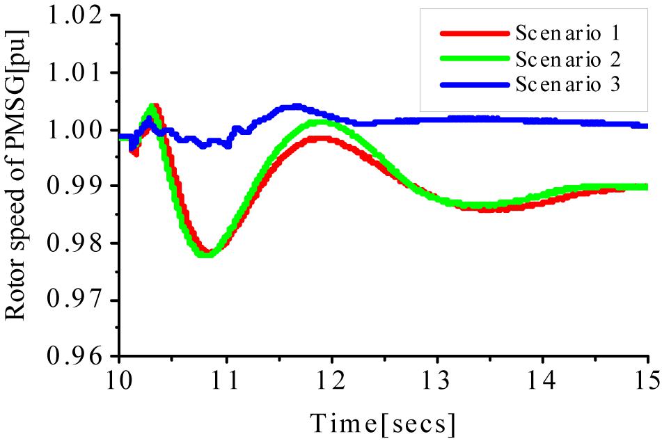
Figure 9. Rotor speed of PMSG without OVPS.
The system performance was evaluated using PSCAD/EMTDC (Pscad/Emtdc Manual, 2016) environment. The fault type is a severe three-phase of 100 ms happening at 10.1 s, with the circuit breakers operation sequence opening and reclosing at 10.2 and 11 s, respectively, on the faulted line at the terminals of the PMSG wind turbine. Figure 5 shows the response of the PMSG wind turbine DC-link voltage for the three scenarios of Table 2. With a high IGBT turn on resistance of 0.003 Ω in scenario 3, the DC-link variable of the wind generator recovered on time, compared to a low resistance of 0.001 Ω for scenario 1 and 0.002 Ω for scenario 2, respectively. It should be noted that the IGBT’s turn off resistance and forward break over voltage and reverse withstand voltage were kept constant in the course of the study. In Figure 6, the terminal voltage for scenarios 1 and 2 gave more voltage overshoot and dip, with less settling time than scenario 3. In Figure 7, the response of the active power of the wind generator was better controlled in scenario 3, with less over shot, few oscillations, and faster settling time. The PMSG reactive power dissipation in Figure 8 was more for scenarios 1 and 2, respectively. While in scenario 3, the higher resistance value of the turn on resistance was able to limit the reactive power dissipation within the power converter limit. In Figure 9, the rotor speed of the wind generator recovered faster for scenario 3, with less overshoot and oscillations, compared to the other scenarios. Scenarios 1 and 2 show a huge depression and recovery of the wind generator rotor speed compared to scenario 3 with mitigated effects of the grid fault on the rotor speed during transient state. This is because an increase in the turn on resistance of the IGBTs of the PMSG wind turbine power converters would decrease the circulation of currents and boost the capability of the switching mode of the converter’s legs during transient state. Hence, this topology could be a cheaper way to enhance the FRT of the PMSG variable speed wind turbine during transient condition.
A further investigation was carried out for the three scenarios using the same conditions in section A but considering the use of DC-chopper braking resistor for 110% over voltage protection as shown in Table 1. The PMSG variables for this case are shown in Figures 10–14.
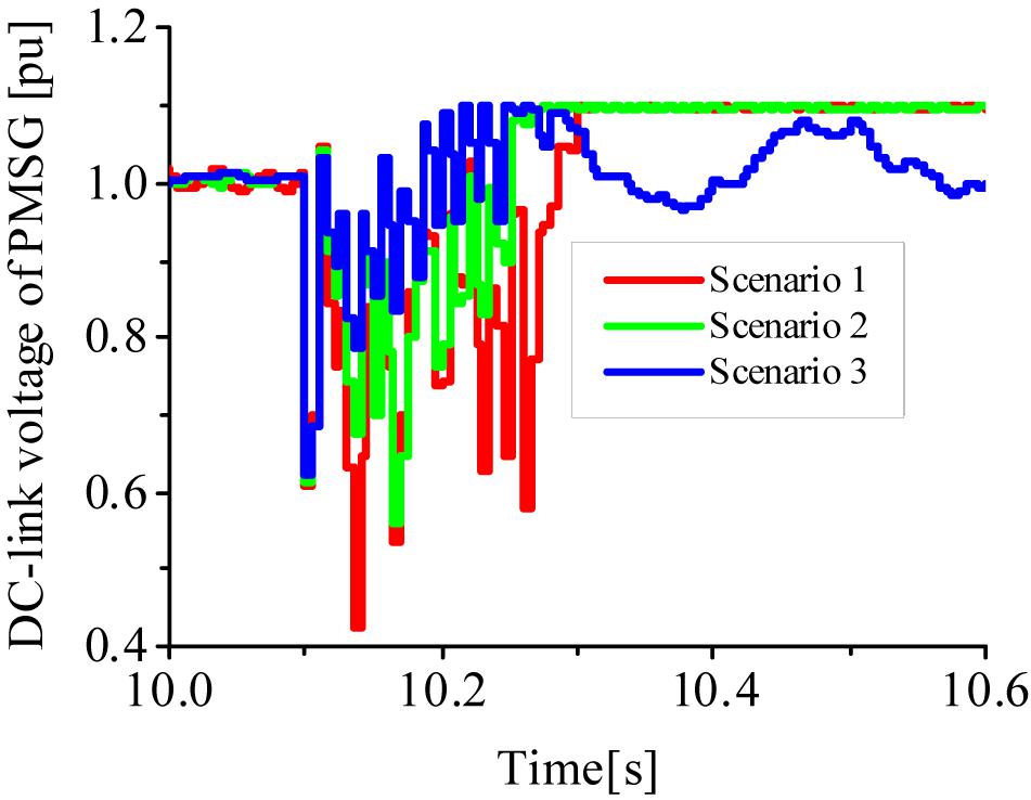
Figure 10. DC-link voltage of PMSG with OVPS.
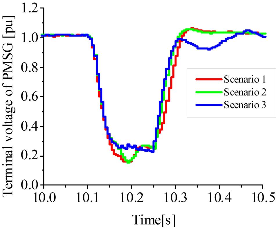
Figure 11. Terminal voltage of PMSG with OVPS.
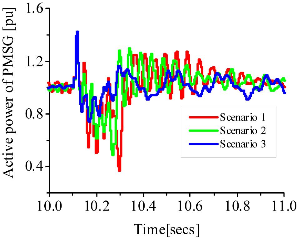
Figure 12. Active power of PMSG with OVPS.
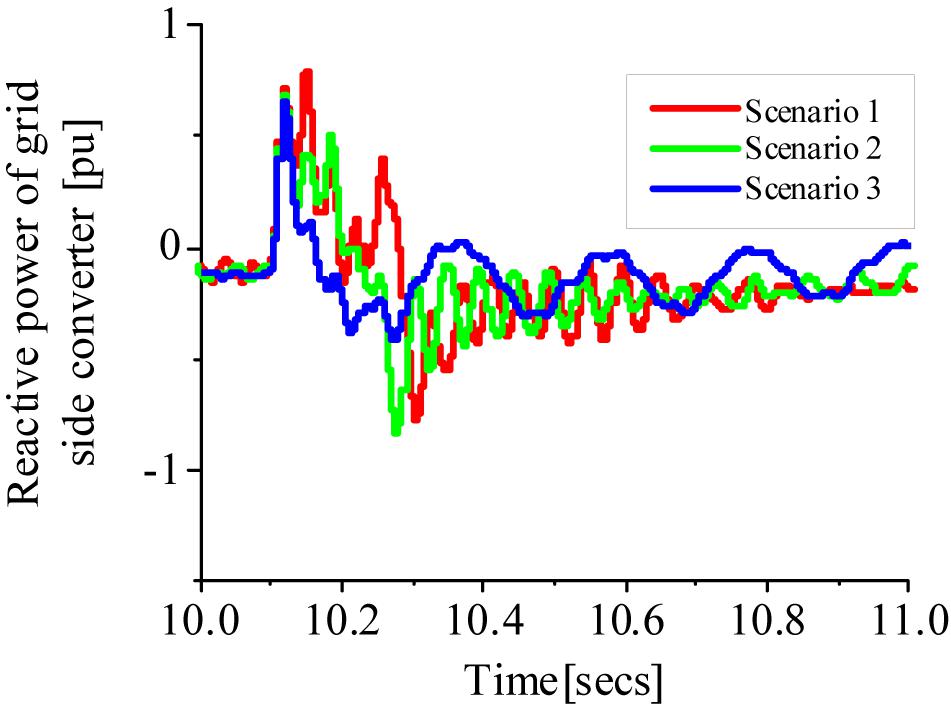
Figure 13. Reactive power of PMSG with OVPS.
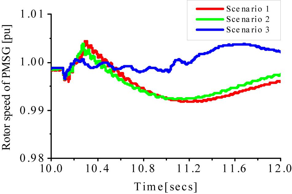
Figure 14. Rotor speed of PMSG with OVPS.
From Figure 10, with the help of the DC chopper connected at the GSC of the PMSG with turbine, the DC-link voltage was maintained within the permissible limit of 110% as set in Table 1 for all the scenarios. It could be observed from Figure 11 that the DC-link overvoltage protection scheme (OVPS) was able to mitigate the effects of the grid disturbance, oscillations, overshoot, and undershoot for scenario 3, which is usually caused by grid fault, due to the fragile nature of the power converters of the wind generator. Thus, the vulnerable power converters of the wind generator are protected during transient state. The response of the terminal voltage of the wind generator’s variable in Figure 11 indicates that the OVPS scheme could help reduce the voltage dip and over shoot in the terminal voltage of the wind turbine for scenario 3. A smoother active power of the wind generator was achieved for scenario 3 in Figure 12 because the effective control of the DC-link voltage by the OVPS has a direct effect on the active power of the wind turbine. The reactive power dissipation was less for scenario 3 with the help of the OVPS as shown in Figure 13. In Figure 14, the rotor speed of the PMSG wind turbine was further improved considering the OVPS for scenario 3. An improved performance of the variables of the PMSG wind turbine during transient state, in scenarios 1 and 2, respectively, was achieved using the OVPS for all the scenarios compared to the case without OVPS in section A; however, the OVPS has little or no effect on scenario 3 in the transient performance of the PMSG wind turbine. Thus, a cheaper and cost-effective way for the enhancement of the PMSG wind turbine is scenario 3, without the circuitry of DC-chopper braking resistor.
In order to compare the performance of the effects of the power converters on the transient stability of the PMSG wind turbine, a further analysis was carried out in this section to investigate the effects of the power converter on the DFIG wind turbine. The same condition of operation was considered as above for the PMSG wind turbine. The simulation results for some of the key variables of the DFIG are shown in Figures 15–19, based on (Okedu and Barghash, 2021).
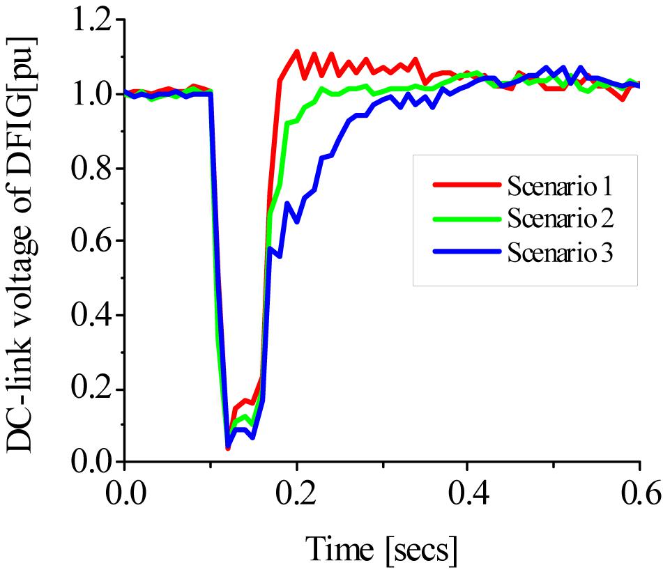
Figure 15. DC-link voltage of DFIG.
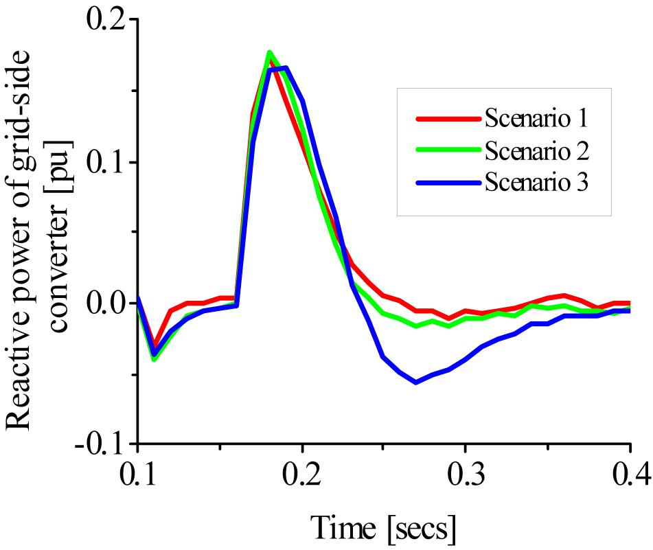
Figure 16. Reactive power of DFIG grid side converter.
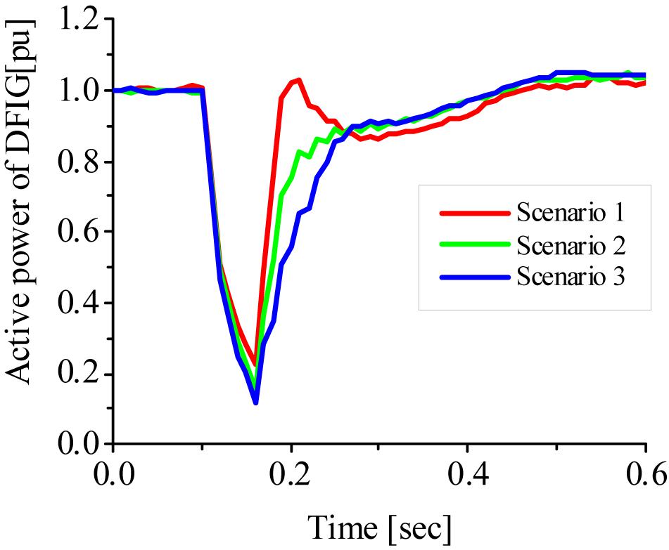
Figure 17. Active power of DFIG.
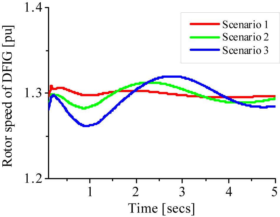
Figure 18. Rotor speed of DFIG.
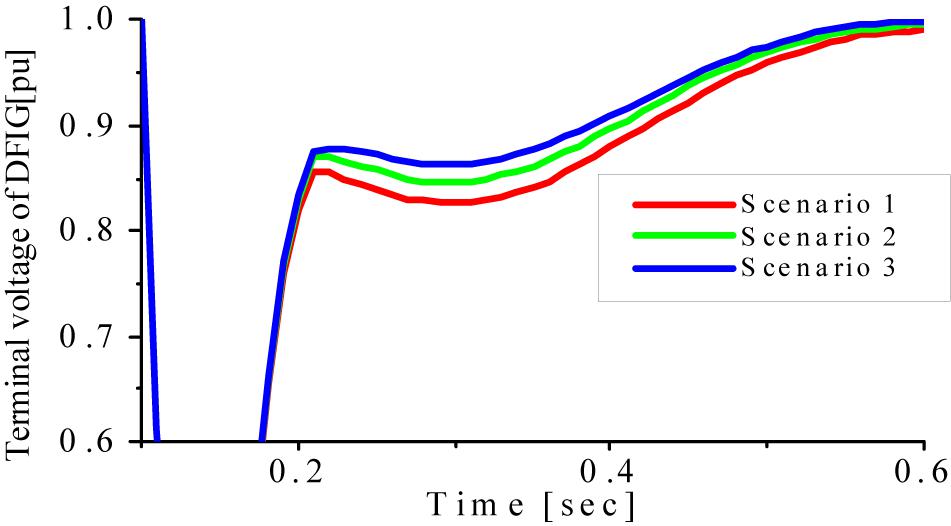
Figure 19. Terminal voltage of DFIG.
Figure 15 shows that for scenario 1, the DFIG DC-link voltage experienced overshoot, while for scenario 3, the terminal voltage was not recovered on time. The effective performance of the DFIG wind turbine terminal voltage was observed in scenario 2. When compared to the PMSG wind turbine, scenario 3 was better than the other two scenarios. The reactive and active power responses in Figures 16, 17 show that the DFIG was effectively stable for scenario 2 compared to the other scenarios; however, scenario 3 gave the effective performance of the PMSG wind turbine. Although scenario 1 gave a better response for the DFIG rotor speed in Figure 18, while in Figure 19, scenario 3 gave the best performance for the terminal voltage variable of the DFIG, however, for the PMSG wind turbine, scenario 3 gave the most effective performance.
This paper investigated the effects of the insulated gate bipolar transistor of the PMSG wind turbine power converters, during transient state. A severe three-phase-to-ground bolted fault was considered in this study during transient condition in order to test the robustness and rigidity of the controllers of the wind generator. Various scenarios were considered, where the turn on resistance of the IGBTs were varied, while keeping the turn off resistance, forward break over voltage, and reverse withstand voltage constant. The study also considered the performance of the wind generator with and without the use of DC-chopper over voltage protection scheme, connected to the grid side converter of the wind generator. The presented results show that a high turn on resistance of the IGBTs of the PMSG power converters could help improve the performance of the variables of the wind generator during transient state, even without considering over voltage protection scheme. This is because an increase in the turn on resistance would limit the excess circulating current that normally occur during transient state of the wind turbine. More so, the performance of the PMSG wind turbine seems to be better with a slightly higher turn on resistance compared to the turn on resistance value for the DFIG wind turbine, based on the presented results. This could be as a result of the full back–back power converter rating for the PMSG wind turbine, as compared to only 20–30% power converter rating for the DFIG wind turbine. As part of future scope, an optimization approach using dragon fly algorithm is the next phase of this work for optimal performance of the wind generator.
The raw data supporting the conclusions of this article will be made available by the authors, without undue reservation.
KO did the conceptualization, literature review, simulations analysis, and writing of the manuscript. HB did part of the literature review and sponsorship of the manuscript. Both authors contributed to the article and approved the submitted version.
This work was sponsored by the German University of Technology (Gutech), Muscat, Oman and the Nisantasi University, Istanbul, Turkey.
The authors declare that the research was conducted in the absence of any commercial or financial relationships that could be construed as a potential conflict of interest.
Ahmed, A. S., Noura, A., Nour, A., Ahmed, M. A., and Walid, S. E. A. (2019). Fuzzy logic-based MPPT technique for PMSG wind generation system. Int. J. Renew. Energy Res. 9, 1751–1760.
Alepuz, S., Calle, A., Busquets, M. S., Kouro, S., and Wu, B. (2013). Use of stored energy in PMSG rotor inertia for low-voltage ride-through in back-to-back NPC converter-based wind power systems. IEEE Trans. Ind. Electron. 60, 1787–1796. doi: 10.1109/tie.2012.2190954
Chen, L., He, H., Chen, H., Wang, L., Zhu, L., Shu, Z., et al. (2017). Study of a modified flux-coupling-type SFCL for efficient fault ride-through in a PMSG wind turbine under different types of faults. J. Elect. Comput. Eng. 40, 189–200.
Firouzi, M., Nasiri, M., Benbouzid, M., and Gharehpetian, G. B. (2020). Application of multi-step bridge-type fault current limiter for fault ride-through capability enhancement of permanent magnet synchronous generator-based wind turbines. Int. Trans. Elect. Energy 30:e12611.
Gencer, A. (2018). Analysis and control of fault ride through capability improvement PMSG based on WECS using active crowbar system during different fault conditions. Elektron. Elektrotech. 24, 64–69.
Ghatikar, G., Mashayekh, S., Stadler, M., Yin, R., and Liu, Z. (2016). Distributed energy systems integration and demand optimization for autonomous operations and electric grid transactions. Appl. Energy 167, 432–448. doi: 10.1016/j.apenergy.2015.10.117
Hossain, M. E. (2017). A non-linear controller based new bridge type fault current limiter for transient stability enhancement of DFIG based wind farm. Electr. Power Syst. Res. 152, 466–484. doi: 10.1016/j.epsr.2017.07.033
Huang, C., Xiao, X. Y., Zheng, Z., and Wang, Y. (2019). Cooperative control of SFCL and SMES for protecting PMSG-based WTGs under grid faults. IEEE Trans. Appl. Supercond. 29:5601106.
Jerin, A. R. A., Kaliannan, P., and Subramaniam, U. (2017). Improved fault ride through capability of DFIG based wind turbines using synchronous reference frame control based dynamic voltage restorer. ISA Trans. 70, 465–474. doi: 10.1016/j.isatra.2017.06.029
Lee, S. W., and Chun, K. H. (2019). “Adaptive sliding mode control for PMSG wind turbine systems. Energies 12:595. doi: 10.3390/en12040595
Li, S., Haskew, T. A., and Xu, L. (2010). Conventional and novel control design for direct driven PMSG wind turbines. Electr. Power Syst. Res. 80, 328–338. doi: 10.1016/j.epsr.2009.09.016
Li, Y., Xu, Z., and Wong, K. P. (2017). Advanced control strategies of PMSG-based wind turbines for system inertia support. IEEE Trans. Power Syst. 32, 3027–3037. doi: 10.1109/tpwrs.2016.2616171
Mahmoud, A. S., Hany, M. H., Haitham, Z. A., El-Kholy, E. E., and Sabry, A. M. (2019). An adaptive fuzzy logic control strategy for performance enhancement of a grid-connected PMSG-Based wind turbine. IEEE Trans. Ind. Inform. 15, 3163–3173. doi: 10.1109/tii.2018.2875922
Matlab documentation center (2012). Available online at: http://www.mathworks.co.jp/jp/help/ (accessed March 12, 2012).
Michalke, G., Hansen, A. D., and Hartkopf, T. (2007). “Control strategy of a variable speed wind turbine with multi-pole permanent magnet synchronous generator,” in Proceedings of the European Wind Energy Conference and Exhibition (Milan), 7–10.
Moghadasi, A., Sarwat, A., and Guerrero, J. P. M. (2016). Multiobjective optimization in combinatorial wind farms system integration and resistive SFCL using analytical hierarchy process. Renew. Energy 94, 366–382. doi: 10.1016/j.renene.2016.03.073
Muyeen, S. M., Al-Durra, A., and Tamura, J. (2011). Variable speed wind turbine generator system with current controlled voltage source inverter. Energy Convers. Manag. 52, 2688–2694. doi: 10.1016/j.enconman.2011.02.001
Nasiri, M., and Mohammadi, R. (2017). Peak current limitation for grid-side inverter by limited active power in PMSG-based wind turbines during different grid faults. IEEE Trans. Sustain. Energy 8, 3–12. doi: 10.1109/tste.2016.2578042
Okedu, K. E., and Barghash, H. (2021). Enhancing the performance of DFIG wind turbines considering excitation parameters of the insulated gate bipolar transistors and a new PLL scheme. Front. Energy 8:373. doi: 10.3389/fenrg.2020.620277
Okedu, K. E., Muyeen, S. M., Takahashi, R., and Tamura, J. (2011). “Protection schemes for DFIG considering rotor current and DC-link voltage,” in Proceedings of the 24th IEEE-ICEMS (International Conference on Electrical Machines and System) (Beijing), 1–6.
Okedu, K. E., Muyeen, S. M., Takahashi, R., and Tamura, J. (2012). Wind farms fault ride through using DFIG with new protection scheme. IEEE Trans. Sustain. Energy 3, 242–254. doi: 10.1109/tste.2011.2175756
Priyadarshi, N., Ramachandaramurthy, V., Padmanaban, S., and Azam, F. (2019). An ant colony optimized MPPT for standalone hybrid PV-wind power system with single Cuk converter. Energies 12:167. doi: 10.3390/en12010167
Pulido, A. B., Romero, J., and Enriquez, H. C. (2018). Robust active disturbance rejection control for LVRT capability enhancement of DFIG-based wind turbines. Control Eng. Pract. 77, 174–189. doi: 10.1016/j.conengprac.2018.06.001
Rosyadi, M., Muyeen, S. M., Takahashi, R., and Tamura, J. (2012). A design fuzzy logic controller for a permanent magnet wind generator to enhance the dynamic stability of wind farms. Appl. Sci. 2, 780–800. doi: 10.3390/app2040780
Singaravel, M. M. R., and Daniel, S. A. (2015). MPPT with single DC-DC converter and inverter for grid connected hybrid wind-driven PMSG-PV system. IEEE Trans. Ind. Electron. 62, 4849–4857. doi: 10.1109/tie.2015.2399277
Toshiba Electronic Devices & Storage Corporation. (2018). IGBTs (Insulated Gate Bipolar Transistor) application note. Tokyo: Toshiba Electronic Devices & Storage Corporation, 6–8.
Yehia, D. M., Mansour, D. A., and Yuan, W. (2018). Fault ride-through enhancement of PMSG wind turbines with DC microgrids using resistive-type SFCL. IEEE Trans. Appl. Supercond. 28:5603105.
Youjie, M., Long, T., Xuesong, Z., Wei, L., and Xueqi, S. (2019). Analysis and control of wind power grid integration based on a permanent magnet synchronous generator using a fuzzy logic system with linear extended state observer. Energies 12:2862. doi: 10.3390/en12152862
Keywords: permanent magnetic synchronous generators, wind energy, transient state, insulated gate bipolar transistors, power converters
Citation: Okedu KE and Barghash H (2021) Enhancing the Transient State Performance of Permanent Magnet Synchronous Generator Based Variable Speed Wind Turbines Using Power Converters Excitation Parameters. Front. Energy Res. 9:655051. doi: 10.3389/fenrg.2021.655051
Received: 18 January 2021; Accepted: 08 March 2021;
Published: 21 April 2021.
Edited by:
Alexis B. Rey-Boué, Universidad Politécnica de Cartagena, SpainReviewed by:
Mojtaba Nasiri, Trinity College Dublin, IrelandCopyright © 2021 Okedu and Barghash. This is an open-access article distributed under the terms of the Creative Commons Attribution License (CC BY). The use, distribution or reproduction in other forums is permitted, provided the original author(s) and the copyright owner(s) are credited and that the original publication in this journal is cited, in accordance with accepted academic practice. No use, distribution or reproduction is permitted which does not comply with these terms.
*Correspondence: Hind Barghash, aGluZC5iYXJnaGFzaEBndXRlY2guZWR1Lm9t
Disclaimer: All claims expressed in this article are solely those of the authors and do not necessarily represent those of their affiliated organizations, or those of the publisher, the editors and the reviewers. Any product that may be evaluated in this article or claim that may be made by its manufacturer is not guaranteed or endorsed by the publisher.
Research integrity at Frontiers
Learn more about the work of our research integrity team to safeguard the quality of each article we publish.