- Department of Safety Engineering, Heilongjiang University of Science and Technology, Harbin, China
Hydrate-based gas separation is a potential technology for CO2 recovery and storage, and its products can be used for fire prevention and control in mines. Promoters are often employed to accelerate or moderate hydrate formation. In this study, experiments were performed to examine the effects of different concentrations of the thermodynamic promoter tetrahydrofuran (THF) and kinetic promoter sodium dodecyl sulphate (SDS) on CO2 hydrate formation under stirring. The results showed that THF significantly shortens the induction time of CO2 hydrates; however, because THF occupies a large cavity in the hydrate structure, it also reduces the gas absorption and hydrate formation rate. SDS has no obvious effect on the induction time of hydrates, but it can increase the gas storage density and hydrate formation rate. Using THF and SDS together consumed more CO2 than using THF alone or pure water. The peak gas consumption rate was 2.3 times that of the THF system. The hydrate formation efficiency was improved by including both THF and SDS, which maximized both the hydrate formation rate and total gas uptake.
Introduction
The development of the global economy and rapid growth of fossil fuel consumption has sharply increased the CO2 content in the atmosphere, which has aggravated the greenhouse effect and seriously affected Earth’s environment (Kasman and Duman, 2015). Thus, CO2 disposal has become an international concern (Bachu, 2000). Hydrate technology provides a new approach to the recovery and storage of CO2 gas (Gabitto and Tsouris 2006) and has been identified by the US Department of Energy as one of the most promising options for CO2 recovery (Elwell and Grant 2006).
CO2 hydrates have shown potential as a fire-extinguishing material (Hatakeyama and Aida 2008) owing to their CO2 gas storage capacity and cold storage capacity. Due to the existence of CH4 in coal mine, once a fire occurs, it is easy to cause gas explosion. CO2 hydrate releases a large amount of CO2 gas in the process of extinguishing the fire, which can play the role of flame retardant and explosion suppression, Thus CO2 hydrates have broad application prospects (Huang et al., 2014) to be used for fire control in mines. Although CO2 hydrate technology has many advantages, such as gas storage capacity and a hydrate formation pressure and temperature that are relatively easy to achieve, the formation rate and gas storage capacity need to be improved.
The application of CO2 hydrates necessitated the systems to have higher gas storage capacity, lower energy consumption, and higher efficiency of formation rate. The formation of CO2 hydrate includes two processes: nucleation and growth. The nucleation of hydrate formation is the formation process of the crystal nucleus exceeding the critical size (Ripmeester and Alavi, 2016). The process from the thermodynamic metastable state to the formation of the crystal nucleus exceeding the critical size is an induced nucleation process, which is described by the induction time. The length of the induction time is one of the criteria to judge the hydrate formation speed.
In recent years, promoters have often been used to improve the hydrate formation rate and storage capacity (Zheng et al., 2017). Depending on their mechanism, hydrate promoters can be divided into thermodynamic and kinetic promoters (Mech et al., 2016; Sun et al., 2019). Thermodynamic promoters are used to reduce the phase equilibrium pressure or improve the phase equilibrium temperature; the most commonly used include tetrahydrofuran (THF) (Beheshtimaal and Haghtalab 2017; Yue et al., 2018), tetrabutylammonium bromide (Babaee et al., 2018; Yue et al., 2018) and propane (Dashti et al., 2015). THF is a water-soluble organic liquid under the conditions of normal pressure and 4.4°C with a SII hydrate formation structure. Veluswamy et al. (2017) studied the formation kinetics of CO2 hydrates in the presence of THF and showed that the hydrate formation kinetics of different guest molecules was affected by the presence of THF. THF has mostly been used to study CO2 separation technology based on hydrates. Yang et al. (2018) studied capturing CO2 from flue gas by using a TBAB/THF compound additive. Their results showed that adding 19 wt% THF had an obvious effect on hydrate formation. Other researchers (Zhong et al., 2015; Yue et al., 2018; Yi et al., 2019) studied hydrate technology for separating CO2 and CH4 and found that THF improves the phase equilibrium parameters but reduces the CO2 gas separation efficiency. Kinetic promoters are used to improve the hydrate formation rate and gas storage density and including sodium dodecyl sulphate (SDS), sodium dodecyl benzene sulfonate and tween-80 (Dashti et al., 2015). SDS is considered as one of the best kinetic promoters (Kumar et al., 2015). Partoon et al. (2013) studied the formation kinetics of CO2 hydrate in SDS solution and showed that adding SDS significantly increases CO2 absorption and the hydrate formation rate. In recent years, some scholars have begun to study the combined effects of THF and SDS on CO2 hydrate formation. Yang et al. (2013) suggested that SDS/THF can reduce the hydrate phase equilibrium pressure and increase hydrate gas consumption, while Lirio et al. (2013) suggested that SDS does not significantly increase the CO2 hydrate gas storage capacity.
Although many studies have considered the kinetic characteristics of CO2 hydrate formation, research on the effect and mechanism of additives (THF and THF/SDS composite) under stirring is still very limited. To explore the relationship between the promoter and CO2 hydrate formation under stirring and determine the formation mechanism of CO2 hydrates, this study examined the effects of THF and THF/SDS on the formation kinetics of CO2 hydrates. Under stirring action, three THF concentrations (1, 2 and 3 mol%) and three THF/SDS concentrations (2 mol% THF + 0.05 wt% SDS, 2 mol% THF + 0.1 wt% SDS and 2 mol% THF + 0.2 wt% SDS) were used to study the formation kinetics of CO2 hydrates. An improved calculation method of the gas consumption was developed, and the effects of the THF and THF/SDS concentrations on the hydrate formation time, CO2 gas consumption and rate of hydrate formation were evaluated. The hydrate formation method adopted in this study can also provide some guidance for the rapid formation of CO2 hydrates, which is of great significance for CO2 recovery and storage in the enclosed space of a coal mine as well as mine fire control.
Experimental
Materials
CO2 gas was provided by Harbin Liming Gas Company Limited. THF and SDS at 99.9% purity were provided by Harbin Branch Analytical Instrument Company Limited. All experiments were performed with deionized and distilled water.
Experimental Apparatus
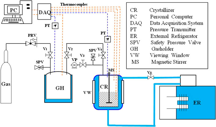
Figure 1 shows the setup for the CO2 hydration experiments. The reactor (crystalliser) comprised 316 stainless steel with an inner diameter of 9.2 cm, height of 26.5 cm and volume of 1,500 cm3. It was surrounded by a water jacket with a temperature controlled by an external refrigerator. A rectangular viewing window and lighting window were on the broad side of the reactor for visual observation. Two thermocouples (Omega, T-type, ±0.01 K) were inserted into the reactor to measure the temperatures of the gas and liquid phases. A pressure transducer (model 3051 S, ±20 kPa) was used to monitor the pressure in the reactor. The gasholder in the system was used to realize an accurate gas supply of the reactor. It comprised 304 stainless steel with a volume of 12 L. A pressure transducer and thermocouple were inserted into the gasholder with the same models and accuracies as those in the reactor. Both pressure and temperature data were acquired with a data acquisition system (National Instruments) and recorded on a computer with the software LabVIEW. A data acquisition unit was connected to a computer to collect the temperature and pressure data every second.
Experimental Procedure
As the thermodynamic promoter, THF can greatly improve the thermodynamic conditions of CO2 hydrate. According to the literature, According to literature, small amounts of THF can change the structure of CO2 hydrate from SI to SⅡ. Structure II hydrates are constituted of 16 small cavities and eight large cavities, count then 136 H2O molecules, THF occupies all the eight large cavities and then only the 16 small cages can be occupied by CO2 molecules. When the molar concentration of THF is 5.6 mol%, the gas consumption is 0.1176 mol CO2 per mol H2O. CO2-H2O forms SI hydrate without THF, Structure SI hydrate are constituted of two small cavities and six large cavities, count then 46 H2O molecules. CO2 molecules occupy all the cavities. when the molar concentration of THF is 0 mol%, the gas consumption is 0.1739 mol CO2 per mol H2O. According to the analysis of the thermodynamic conditions for improving hydrate by THF, the optimal concentration of THF is 5.6 mol%. According to the analysis of hydrate kinetics as gas consumption, the lower THF concentration, the gas consumption is better. Therefore, in this study the concentration of THF is prepared as 1 mol%, 2 mol% and 3 mol% in order to find the optimal concentration which can take both kinetics and thermodynamics into account.
Three THF solutions (1.0, 2.0 and 3.0 mol%) and three THF/SDS solutions (2 mol% THF + 0.05 wt%, 2 mol% THF + 0.1 wt% and 2 mol% THF + 0.2 wt%) were prepared. In order to study the effect of THF and THF/SDS on the kinetics of CO2 hydrate, the pure water system was used as a reference for comparison against the THF and THF/SDS solutions. An experimental sample comprised 650 ml aqueous solution containing one of the promoter concentrations considered in this study. The reactor was cleaned thoroughly with distilled water before each experimental run. Then, the reactor was filled with one of the prepared aqueous solutions. The temperature of the external incubator was adjusted until the system temperature was fixed at 288.15 K (i.e. liquid phase temperature). The gasholder was inflated to obtain a pressure of 3.30 MPa at a constant temperature in the gasholder. Then, the air source was closed. Subsequently, the gas supply valve of the reactor was opened, and the reactor was supplied with CO2 by the gasholder for 12 h. The pressure in the reactor was controlled to 3.0 MPa after the dissolution equilibrium was reached. Subsequently, the gas supply valve of the reactor was closed, the stirrer was opened with 500r/min, and the external incubator temperature was adjusted to 271.15 K CO2 hydrate formation experiments were carried out at a constant volume and fixed temperature. As the hydrate formation progressed, the pressure kept dropping because of gas consumption. The formation experiment was allowed to terminate until there was no significant pressure drop within 2 h.
Calculation Methods
Gas Consumption of SⅠ CO2 Hydrates
In this experiment, SⅠ CO2 hydrates formed in the pure water system (Kang et al., 2001). However, the high solubility of CO2 in the aqueous solution meant that calculating the gas consumption of the CO2 hydrates required determining the variation of CO2 not only in the gas phase but also in the liquid phase. According to the law of mass conservation, the molar quantity of CO2 in the reactor is constant at any time. Thus, the CO2 consumption during hydrate formation can be calculated as follows:
where
where
The molar quantity of gaseous CO2 (
where P, V and T are the pressure, volume and temperature, respectively, of the gas phase in the reactor at the time t. The ideal-gas state R is 8.31 J/(mol K). Z is the gas compressibility calculated with a Pitzer correlation (Smith et al., 2011):
B0 and B1 are calculated as follows:
where
The molar quantity of CO2 in the liquid phase
where
Hashemi et al. (2006) used the Gibbs free energy minimization model to obtain the dissolution law of CO2 gas in the presence of hydrates. Diamond and Akinfiev (2003) obtained the solubility of CO2 gas in the presence of hydrates, which can be calculated as follows:
Eq. 8 has high accuracy in the temperature range of −1.48°C–9.93°C and ignores the effect of pressure on CO2 solubility. Thus, it can be used to calculate the solubility of CO2 gas in the presence of hydrates. Eq. 1–8 can be used to derive the following equation for calculating the CO2 consumption during hydrate formation:
Gas Consumption of SII CO2 Hydrates
THF was used to study the influence of a promoter on the kinetics of CO2 hydrate formation. According to the literature, small amounts of THF can change the structure of CO2 hydrates from the SI type to the SII type (Kang et al., 2001). The CO2 consumption of SII hydrates is calculated as follows:
SII hydrates comprise 16 small cavities and eight large cavities with 136 H2O molecules. According to Marinhas et al. (2007), THF occupies all eight large cavities; then, only the 16 small cavities can be occupied by CO2 molecules. Then, SII hydrates have a hydration number
In order to calculate the gas consumption of CO2 hydrate with different crystal forms, it assumed that only a single structure hydrate is formed in hydrate formation stage which determined by the change of hydrate pressure and temperature in this study.
Normalized CO2 Consumption
The gas consumption calculated with Eqs 9, 10 can be further divided by the number of moles of water in the system to obtain the normalized gas consumption (mol gas/mol water) (Zheng et al., 2019):
The rate of gas uptake can be calculated with the forward difference method:
where
Error Calculation
The error indicates the degree of dispersion of numerical values to the average value, and it can be calculated according to the standard deviation:
where n is the number of data values, x is the average value and xi is a certain value.
Results and Discussion
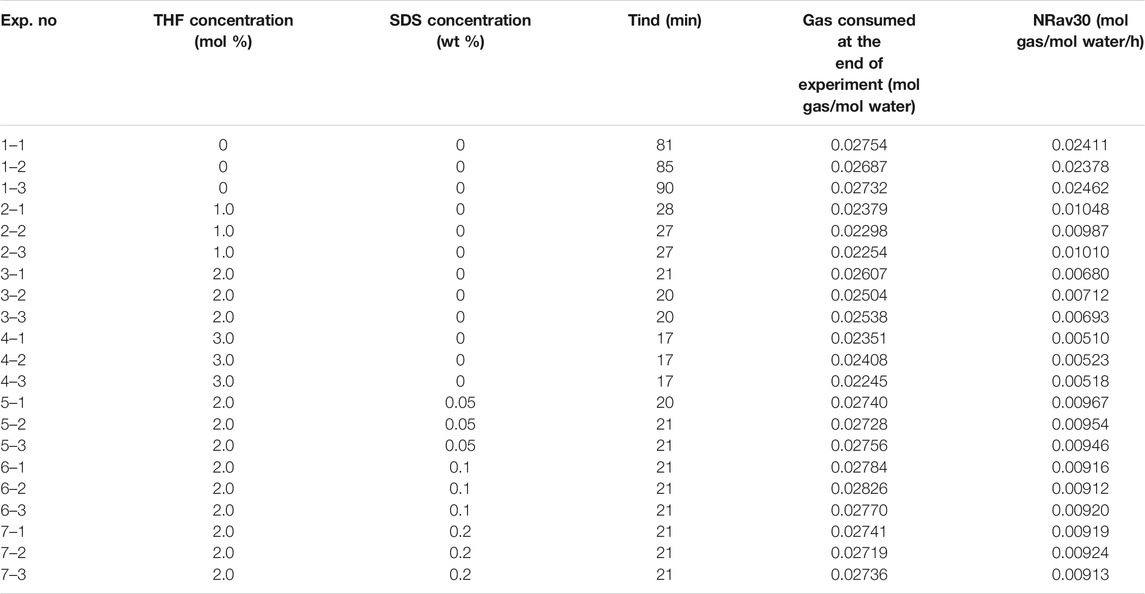
The influence of the promoters THF and THF/SDS on CO2 hydrate formation under stirring action was studied. At a fixed pressure of 3.0 MPa and stirring speed of 500 r/min, three concentrations of THF (1.0 mol%, 2.0 mol% and 3.0 mol%) and three concentrations of THF/SDS (2.0 mol% THF + 0.05 wt% SDS, 2.0 mol% THF + 0.1 wt% SDS and 2.0 mol% THF + 0.2 wt% SDS) were configured as the research objects. Table 1 presents the experimental results for CO2 hydrate formation, which includes the induction time tind (min), standardized gas consumption at the end of the experiment
Effect of THF on the Formation Kinetics of CO2 Hydrates
Eq. 9 shows that the gas consumption of CO2 hydrates depends not only on the initial state but also on the crystal structure when the hydrate is formed. The formation process and crystal structure of CO2 hydrate are different with different promoters.
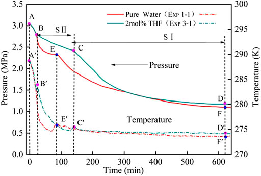
Figure 2 shows the process of CO2 hydrate formation under the action of THF with the stirrer 500 r/min. The hydrate formation curve of the 2 mol% THF system was significantly different from that of the pure water system. In the pure water system, the pressure and temperature in the reactor dropped with the temperature of the water bath (i.e. section A–E); this period was defined as the induction time Tind. After point E was reached, the phase equilibrium in the reactor was broken, and a large amount of hydrates began to form. After 600 min, the pressure in the kettle was generally constant, and the hydration experiment ended. The hydration process for the 2 mol% THF system can be divided into two stages: sections B–C and C–D. As the temperature in the kettle decreased, the pressure dropped from point A to B; hydrates began to form, and the pressure inside the kettle decreased further. After point C was reached, the pressure began to drop sharply. After 600 min, the pressure in the reactor was generally constant, and the hydration experiment ended. The hydrate formation process for the THF system has two stages mainly because of the thermodynamic promoter THF. According to the literature (Kang et al., 2001; Marinhas et al., 2007), a small amount of THF can change the structure of CO2 hydrates from the SI type to the SII type. For a single SII THF hydrate, THF occupies all eight large cavities. It can be inferred that THF occupies the large cavities in the THF system, and only the 16 small cavities can be occupied by CO2 molecules (Mohammadi and Richon 2009; Lee et al., 2012; Mech and Sangwai 2014; Kumar et al., 2018). This reduces the gas consumption and gas consumption rate compared to those of the SI hydrates. In the CO2 + 2 mol% THF system, THF causes the SII hydrates to form first in section B–C section. At point C, the SII hydrates begin to form SI hydrates. CO2 begins to be consumed in large quantities, and SI hydrates are formed in section C–D.
The induction time, standardized gas consumption and hydration formation rate can be used to express the kinetic performance of the hydrate formation process under the action of stirring. To investigate the effects of different concentrations of THF on the formation kinetics of CO2 hydrates, the CO2 hydrate induction time, standard gas consumption and hydration formation rate were measured for the 1.0 mol% THF, 2.0 mol% THF and 3.0 mol% THF solutions under 500 r/min stirring.
Induction time studies are important in investigating the kinetics of CO2 hydrate formation under stirring. The time interval between establishment of super saturation and the formation critical nuclei is called as the induction time. in this study, there is a cooling process in the formation of CO2 hydrate, which decreases from 288.15 k to 271.15 k, Therefore, the real induction is not easy to determine. As to Yang et al. (2013), the induction time was defined as the time from the start of cooling process to the time of hydrate formation, when the temperature begins to rise. Although this time is not a real induction time for CO2 hydrate nucleation, it is convenient for discussing the results and has no negative impact on the conclusions. In this study the Initial pressure and temperature of all experiments were set to 3 MPa and 288.5 K, at the same time the cooling rate are the same. thus, the effects of THF on the hydrate induction time can be expressed by the time elapsed from the start of cooling to abundant hydrate formation.
It can be seen from Figure 3 that during the induction period of CO2 hydrate formation, the solution temperature in the reactor began to decrease from 288.15 k. Within 17 min when the temperature of the solution decreased from 288.15 k to 284.25 k, the pressure and temperature curves of the four systems almost coincide; with the decrease of temperature, the pressure in the reactor began to drop rapidly, Part of the reason is the drop of gas phase temperature in the reactor, the other part of the reason is the increase of CO2 solubility and the entry of a large amount of CO2 into solution. After 17 min, the temperature of 3 mol% THF system began to rise, and the pressure drop rate decreased significantly. It was mainly due to the formation of hydrate in the reactor, which consumed a large amount of solution and released a large amount of CO2. Then the induction period of the system ended and entered the hydrate growth period. The temperature and pressure of other systems continued to drop rapidly. The same as 3 mol% THF system, the induction period of 2 mol% THF system ended at 21 min, the induction period of 1 mol% THF system ended at 28 min, pure water system ended at 81 min.
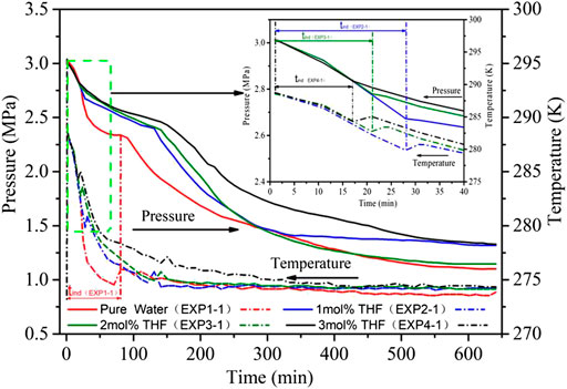
FIGURE 3. Pressure and temperature evolution of CO2 hydrate formation with different THF concentrations at 3.0 MPa.
Table 1 demonstrate that the average induction time of CO2 hydrates was 85.3 min in the pure water system, 27.3 min in the 1 mol% THF system, 20.3 min in the 2 mol% THF system and 17.0 min in the 3 mol% THF system under 500 r/min stirring. Adding the thermodynamic promoter THF shortened the induction time by nearly 80%, which confirms that THF can reduce the induction time of CO2 hydrates under stirring action. Increasing the molar concentration of THF reduced the induction time. This is consistent with the law obtained in the literature (Sabil et al., 2010). From the perspective of the CO2 hydrate formation process, the formation time of SII hydrates gradually increases with increasing THF concentration; the hydrate formation rate does not change much, while the pressure and rate of SⅠ hydrate formation change greatly. SI hydrate formation was fastest in the 2 mol% THF system under stirring action.
THF can greatly shorten the induction time of CO2 hydrates under stirring action, which lays a foundation for application to CO2 hydrate technology. However, the influence of THF on the gas consumption of CO2 hydrate formation needs further analysis. As shown in Figure 4, the shape of the gas consumption curve for hydration formation differed between the THF and pure water systems under stirring action. In the pure water system, the gas consumption curve increased sharply at the beginning of hydrate formation. Over time, the gas consumption curve gradually flattened and reached an equilibrium state after 570 min. For the THF system, the gas consumption curve had two peaks. The first peak was lower than that of the pure water system and was caused by the formation of SII hydrates. The second peak represented the formation of SI hydrates. The final gas consumption of CO2 hydrates was 0.02724 mol/mol in the pure water system (after normalisation). The maximum CO2 gas consumption of the 2 mol% THF system was 0.02550 mol/mol, which is a reduction of 6.5%. The final gas consumptions of the 1 mol% and 3 mol% THF systems were nearly equal at 0.02310 and 0.02335 mol/mol, respectively, which are 14.3% less than that of the pure water system. Therefore, 2 mol% THF had the least impact on CO2 gas consumption among the THF systems under stirring action.
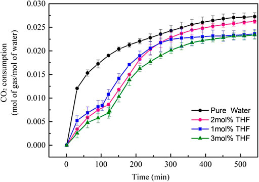
FIGURE 4. CO2 consumption curves (normalized by water amount) during CO2 hydrate formation with different initial molar concentrations of THF.
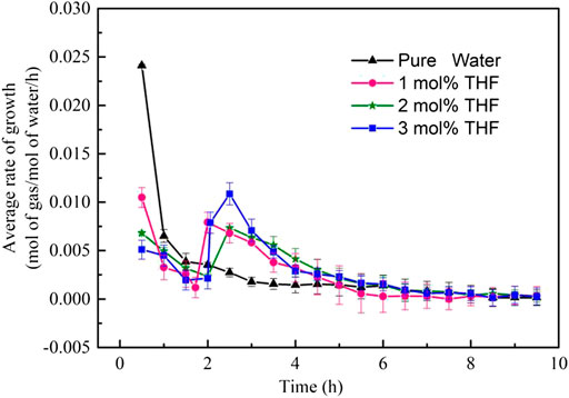
The rate of formation is another influencing factor on the formation kinetics of CO2 hydrates. The gas consumption rate was sampled for all systems to evaluate the rate of CO2 hydrate formation. The gas consumption rate was calculated according to Eq. 13. Figure 5 shows the gas consumption rates of CO2 hydrates in different THF systems. All THF systems exhibited a very high hydrate formation rate at the beginning of the formation process under stirring action; then, the curve began to decrease before rising again after some time. In terms of the hydrate formation process, the initial hydrate formation rate was high when the SII hydrates had a low gas consumption rate, and the hydration formation rate decreased as the gas consumption rate of SI hydrates increased. SII hydrates had a lower gas consumption rate than SI hydrates in the presence of THF. The 1.0 mol% THF, 2.0 mol% THF and 3.0 mol% THF systems had hydrate formation rates of 0.0105, 0.0068 and 0.0051 mol/mol/h, respectively; all of these rates are lower than that of the pure water system at 0.0241 mol/mol/h. At a higher THF concentration, more SII hydrates are formed. More THF molecules competed with CO2 for the hydrate cavities, which inhibited gas consumption. As the formation of SII hydrates ended, the formation of SI hydrates began, and the gas consumption rate achieved a second peak. After that, the formation rate of all systems gradually decreased and finally reached zero after about 570 min.
The above analysis shows that THF can improve the conditions for CO2 hydrate formation and greatly shorten the induction time under stirring action. However, the presence of THF reduces the gas consumption and gas consumption rate of hydrates. The gas consumption and gas consumption of the three THF systems are combined. The 2 mol% THF system had the highest average gas consumption rate and average hydrate formation rate among the THF systems and thus is the best choice for CO2 hydrate formation.
Effect of THF/SDS on the Formation Kinetics of CO2 Hydrates
To improve the gas storage capacity and gas storage density, the promoter SDS was added to the 2 mol% THF system under stirring action. Three solutions were prepared: 2 mol% THF + 0.05 wt% SDS, 2 mol% THF + 0.10 wt% SDS and 2 mol% THF + 0.20 wt% SDS. These were used to study the influence of THF/SDS on the formation kinetics of CO2 hydrates.
Table 1 and Figure 6 indicate that the three THF/SDS systems had an induction time of about 21 min under stirring action, and there was no significant change compared with the 2 mol% THF system. At the same time, during the induction period, the temperature and pressure curves of the three systems almost coincide with the 2 mol% THF system. It indicated that SDS has no obvious effect on the solution compatibilization during the induction period. this is mainly because CO2 gas has relatively high solubility under high pressure, at the same time, under the action of stirring, the gas water contact is strengthened, the equilibrium time of dissolution is shortened, so SDS does not have an obvious solubilization effect. Thus, SDS had almost no effect on the induction time in this study. Although hydrate formation can be divided into two stages, the change in the formation process was not as obvious as that of the THF systems. The pressure drop rate for SII hydrate formation greatly increased to become close to that of SI hydrate formation under stirring action.
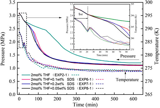
FIGURE 6. Pressure and temperature evolution of CO2 hydrate formation with different THF/SDS concentrations at 3.0 MPa.
Figure 7 shows that the gas consumption of CO2 hydrates differed with the THF/SDS systems under stirring action. Adding SDS increased the gas consumption significantly compared to the 2 mol% THF system: 0.2820, 0.02873 and 0.02835 mol/mol for the 2 mol% THF + 0.05 wt% SDS, 2 mol% THF + 0.10 wt% SDS and 2 mol% THF + 0.20 wt% SDS systems, respectively. These are increases of 10.6%, 12.7% and 11.2%, respectively, compared with the 2 mol% THF system at 0.02747 mol/mol, and were higher than that of the pure water system. Therefore, SDS can improve the gas storage density of hydrates, which is consistent with the results of Partoon et al. (2013). The 2 mol% THF + 0.10 wt% SDS system achieved the highest gas storage density and gas consumption of hydrates under stirring action.
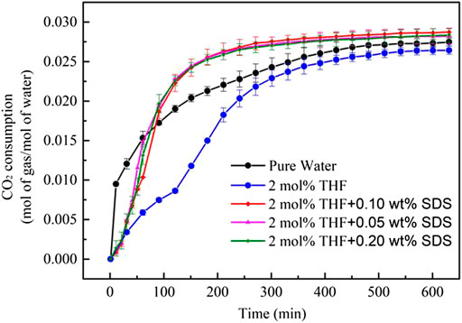
FIGURE 7. CO2 consumption curves (normalized by water amount) during CO2 hydrate formation with different initial molar concentrations of THF/SDS.
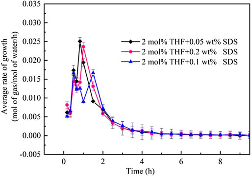
Figure 8 compares the formation rates of CO2 hydrates in the THF/SDS, THF and pure water systems under stirring action. The THF/SDS and THF systems clearly have the same CO2 hydrate formation rate curve with two peaks, but the THF/SDS systems have higher peaks than the THF system. The first peak for the 2 mol% THF + 0.10 wt% SDS system was 0.0160 mol/mol/h, while the second peak was 0.01665 mol/mol/h. These are 2.3 times the values of the THF system peaks (0.0068 and 0.00734 mol/mol/h, respectively). This indicates that adding SDS can increase the hydrate formation rate. The hydration reaction was basically completed 3 h after hydrate formation; at the same time, CO2 hydrate formation was at its second peak in the THF system and was far from over. Therefore, SDS can greatly increase the hydrate formation rate, which is consistent with the results of Partoon et al. (2013).
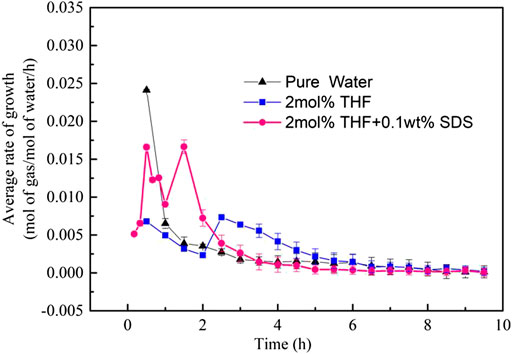
FIGURE 8. Rate of CO2 hydrate formation at different initial molar concentrations of 2 mol% THF + 0.10 wt% SDS.
Figure 9 shows the hydrate formation rates of the THF/SDS systems under stirring action. Although the two peaks of the 2 mol% THF + 0.10 wt% SDS system were not as high as those of the other two systems, the average hydrate formation rate was higher than those of the other two systems. Thus, the 2 mol% THF + 0.10 wt% SDS was superior to the other two systems.
In summary, the THF/SDS system does not significantly affect the induction time compared with the THF system, which implies that SDS does not affect the induction time of CO2 hydrates under stirring action. However, the addition of SDS increases the gas consumption and gas consumption rate of CO2 hydrates. Therefore, THF/SDS can be used as a promoter for the industrial preparation of CO2 hydrates under stirring action, and the 2 mol% THF + 0.10 wt% SDS system was determined to have the best kinetic performance.
Conclusion
The formation kinetics of CO2 hydrates with different concentrations of THF and THF/SDS were investigated in a stirred tank reactor with a driving force of 3.0 MPa. The experimental results showed that THF can significantly shorten the induction time of CO2 hydrates to 80% less than that of pure water. However, THF also reduces the gas consumption and gas consumption rate of hydrates; the 2 mol% THF system had the highest gas consumption and gas consumption rate, but these were still decreased by 14.3% compared with pure water. To improve the gas consumption and gas consumption rate, experiments were carried out by adding different concentrations of SDS to 2.0 mol% THF. The experimental results showed that the induction time of the THF/SDS systems was the same as that of the 2.0 mol% THF system, which indicates that SDS has no obvious effect on the induction time under a stirring action. The final CO2 gas consumption was greatest for the 2.0 mol% THF + 0.1 wt% SDS system at 0.02873 mol/mol, which was 1.13 times that of the 2.0 mol% THF system (0.02550 mol gas/mol water) and 1.05 times that of the pure water system (0.02724 mol/mol). Remarkably, SDS increased the gas consumption rate; the 2 mol% THF + 0.10 wt% SDS system had a peak value that was 2.3 times of that of THF system. Considering the induction time, reaction rate and gas consumption, the 2 mol% THF + 0.10 wt% SDS system had the best overall performance.
Although it is limited by assuming single structure hydrate in hydrate formation stage which determined by the change of hydrate pressure and temperature to calculate CO2 Consumption in this study. In the future research, we will further analyze the hydrate crystal structure in the hydrate formation process by Raman Spectroscopy Analyzer, However, the results of this study are significant as a reference for utilizing mine spaces to store CO2 gas and developing methods for fire prevention and control in mines.
Data Availability Statement
The original contributions presented in the study are included in the article/Supplementary Material, further inquiries can be directed to the corresponding authors.
Author Contributions
Conceptualization, HW and QW; Methodology, HW; Validation, HW and QW; Investigation, HW; Resources, BZ; Data Curation, HW; Writing-Original Draft Preparation, HW and BZ; Writing-Review and Editing, HW. Project Administration, BZ. Funding Acquisition, BZ.
Funding
This work was supported by the Research projects of basic scientific research business expenses of provincial colleges and universities in Heilongjiang Province (Hkdqg201904), the National Natural Science Foundation of China (52074111).
Conflict of Interest
The authors declare that the research was conducted in the absence of any commercial or financial relationships that could be construed as a potential conflict of interest.
Acknowledgments
The authors would like to thank Xianli Qin and his team from Heilongjiang University of Science and Technology for their provided experimental guidance. They would also like to thank the reviewers for their insightful and constructive comments.
References
Bachu, S. (2000). Aquifer disposal of CO2: hydrodynamic and mineral trapping. Energy Convers. Manag. 41, 953–970. doi:10.1016/s0196-8904(99)00149-1
Babaee, S., Hashemi, H., Mohammadi, A. H., Naidoo, P., and Ramjugernath, D. (2018). Kinetic study of hydrate formation for argon + TBAB + SDS aqueous solution system. J. Chem. Therm. 116, 121–129. doi:10.1016/j.jct.2017.08.030
Beheshtimaal, A., and Haghtalab, A. (2017). Chemical Engineering Research and Design Thermodynamic modeling of hydrate formation conditions using different activity coefficient models in the presence of tetrahydrofuran (THF). Chem. Eng. Res. Des. 129, 150–159
Dashti, H., Zhehao Yew, L., and Lou, X. (2015). Recent advances in gas hydrate-based CO2 captur. J. Nat. Gas Sci. Eng. 23, 195–207. doi:10.1016/j.jngse.2015.01.033
Diamond, L. W., Akinfiev, N. N., and et al, (2003). Solubility of CO2 in water from-1.5 to 100°C and from0.1to100MPa: evaluation of literature data and thermodynamic modelling. Fluid Phase Equil. 208, 265–290. doi:10.1016/s0378-3812(03)00041-4
Elwell, L. C., and Grant, W. S. (2006). Technology options for capturing CO2-special reports. Power 150, 60–65
Gabitto, J., and Tsouris, C. (2006). Dissolution mechanisms of CO2 hydrate droplets in deep seawaters. Energy Convers. Manag. 47, 494–508. doi:10.1016/j.enconman.2005.05.016
Govindaraj, V., Mech, D., Pandey, G., Nagarajan, R., and Sangwai, J. S. (2015). Kinetics of methane hydrate formation in the presence of activated carbon and nano-silica suspensions in pure water. J. Nat. Gas Sci. Eng. 26, 810–818. doi:10.1016/j.jngse.2015.07.011
Hashemi, S., Macchi, A., Bergeron, S., Servio, P., et al. (2006). Prediction of methane and carbon dioxide solubility in water in the presence of hydrate. Fluid Phase Equil. 246, 131–136. doi:10.1016/j.fluid.2006.05.010
Hatakeyama, T., and Aida, E. (2008). “Fire extinction utilizing carbon dioxide hydrate.” in Proceedings of the 6nd ICGH. Vancouver, BC, Canada, July 6–10, 2008.
Huang, D., Hou, X., and Wu, Y. (2014). Mechanism analysis and capacity evaluation of CO2 storage in coal mine goaf. Environ. Eng. 32, 1076–1080
Kang, S.-P., Lee, H., and Ryu, B.-J. (2001). Enthalpies of dissociation of clathrate hydrates of carbon dioxide, nitrogen, (carbon dioxide + nitrogen), and (carbon dioxide + nitrogen + tetrahydrofuran). J. Chem. Therm. 33, 513–521. doi:10.1006/jcht.2000.0765
Kasman, A., and Duman, Y. S. (2015). CO2 emissions, economic growth, energy consumption, trade and urbanization in new EU member and candidate countries: a panel data analysis. Econ. Modell. 33, 97–103. doi:10.1016/j.econmod.2014.10.022
Kumar, A., Bhattacharjee, G., Kulkarni, B. D., and Kumar, R. (2015). Role of surfactants in promoting gas hydrate formation. Ind. Eng. Chem. 49, 17–32. doi:10.1021/acs.iecr.5b03476
Kumar, A., Vedula, S. S., Kumar, R., and Linga, P. (2018). Hydrate phase equilibrium data of mixed methane-tetrahydrofuran hydrates in saline water. J. Chem. Therm. 117, 2–8. doi:10.1016/j.jct.2017.05.014
Larsen, R., Knight, C. A., and Sloan, E. D. (1998). Clathrate hydrate growth and inhibition. Fluid Phase Equil. 150-151, 353–360. doi:10.1016/s0378-3812(98)00335-5
Lee, Y.-J., Kawamura, T., Yamamoto, Y., and Yoon, J.-H. (2012). Phase equilibrium studies of tetrahydrofuran (THF) + CH4, THF + CO2, CH4 +CO2, and THF + CO2 +CH4 hydrates. J. Chem. Eng. Data 57, 3543–3548. doi:10.1021/je300850q
Li, Z., Zhong, D.-L., Lu, Y.-Y., Wang, J.-L., Qing, S.-L., and Yan, J. (2016). Enhanced separation of carbon dioxide from a CO2+CH4 gas mixture using a hybrid adsorption-hydrate formation process in the presence of coal particles. J. Nat. Gas Sci. Eng. 35, 1472–1479. doi:10.1016/j.jngse.2016.03.081
Lirio, C. F. d. S., Pessoa, F. L. P., and Uller, A. M. C. (2013). Storage capacity of carbon dioxide hydrates in the presence of sodium dodecyl sulfate (SDS) and tetrahydrofuran (THF). Chem. Eng. Sci. 96, 118–123. doi:10.1016/j.ces.2012.10.022
Marinhas, S., Delahaye, A., and Fournaison, L. (2007). Solid fraction modelling for CO2 and CO2-THF hydrate slurries used as secondary refrigerants. Int. J. Refrig. 30, 758–766. doi:10.1016/j.ijrefrig.2006.12.010
Mech, D., Gupta, P., and Sangwai, J. S. (2016). Kinetics of methane hydrate formation in an aqueous solution of thermodynamic promoters (THF and TBAB) with and without kinetic promoter (SDS). J. Nat. Gas Sci. Eng. 35, 1519–1534. doi:10.1016/j.jngse.2016.06.013
Mech, D., and Sangwai, J. S. (2014). Phase stability of hydrates of methane in tetrahydrofuran aqueous solution and the effect of salt. J. Chem. Eng. Data 59, 3932–3937. doi:10.1021/je500841b
Mohammadi, A. H., and Richon, D. (2009). Phase equilibria of clathrate hydrates of tetrahydrofuran + hydrogen sulfide and tetrahydrofuran + methane. Ind. Eng. Chem. Res. 48, 7838–7841. doi:10.1021/ie900774v
Partoon, B., Malik, S. N. A., Azemi, M. H., and Sabil, K. M. (2013). Experimental investigations on the potential of SDS as low-dosage promoter for carbon dioxide hydrate formation. Asia Pac. J. Chem. Eng. 8, 916–921. doi:10.1002/apj.1736
Ripmeester, J. A., and Alavi, S. (2016). Some current challenges in clathrate hydrate science: nucleation, decomposition and the memory effect. Curr. Opin. Solid State Mater. Sci. 20, 344–351. doi:10.1016/j.cossms.2016.03.005
Sabil, K. M., Duarte, A. R. C., Zevenbergen, J., Ahmad, M. M., Yusup, S., Omar, A. A., et al. (2010). Kinetic of formation for single carbon dioxide and mixed carbon dioxide and tetrahydrofuran hydrates in water and sodium chloride aqueous solution. International Journal of Greenhouse Gas Control 4, 798–805. doi:10.1016/j.ijggc.2010.05.010
Smith, J. M., Van Ness, H. C., and Abbott, M. W. (2011). Introduction to chemical engineering thermodynamics. New York, NY: McGraw-Hill
Sun, Q., Azamat, A., Chen, B., Guo, X. Q., and Yang, L. Y. (2019). The effects of alkyl polyglucosides on the formation of CH4 hydrate and separation of CH4/N2 via hydrates formation. Separ. Sci. Technol. 55 (12), 1–7. doi:10.1080/01496395.2018.1559857
Sun, Q., Guo, X., Chapman, W. G., Liu, A., Yang, L., and Zhang, J. (2015). Vapor-hydrate two-phase and vapor-liquid-hydrate three-phase equilibrium calculation of THF/CH4/N2 hydrates. Fluid Phase Equil. 401, 70–76. doi:10.1016/j.fluid.2015.05.024
Veluswamy, H. P., Premasinghe, K. P., and Linga, P. (2017). CO2 hydrates-effect of additives and operating conditions on the morphology and hydrate growth. Energy Procedia 105, 5048–5054. doi:10.1016/j.egypro.2017.03.1019
Yang, M., Song, Y., Liu, W., Zhao, J., Ruan, X., Jiang, L., et al. (2013). Effects of additive mixtures (THF/SDS) on carbon dioxide hydrate formation and dissociation in porous media. Chem. Eng. Sci. 90, 69–76. doi:10.1016/j.ces.2012.11.026
Yang, M., Zhou, H., Wang, P., and Song, Y. (2018). Effects of additives on continuous hydrate-based flue gas separation. Appl. Energy 221, 374–385. doi:10.1016/j.apenergy.2018.03.187
Yi, J., Zhong, D.-L., Yan, J., and Lu, Y.-Y. (2019). Impacts of the surfactant sulfonated lignin on hydrate based CO2 capture from a CO2/CH4 gas mixture. Energy 171, 61–68. doi:10.1016/j.energy.2019.01.007
Yue, G., Liu, A., Sun, Q., Li, X., Lan, W., Yang, L., et al. (2018). The combination of 1-octyl-3-methylimidazolium tetrafluorborate with TBAB or THF on CO2 hydrate formation and CH4 separation from biogas. Chin. J. Chem. Eng. 26, 2495–2502. doi:10.1016/j.cjche.2018.03.014
Zheng, J., Loganathan, N. K., Linga, P., and Loganathan, K. (2019). Natural gas storage via clathrate hydrate formation: effect of carbon dioxide and experimental conditions. Energy Procedia 158, 5535–5540. doi:10.1016/j.egypro.2019.01.590
Zheng, J., Zhang, P., and Linga, P. (2017). Semiclathrate hydrate process for pre-combustion capture of CO2 at near ambient temperatures. Appl. Energy 194, 267–278. doi:10.1016/j.apenergy.2016.10.118
Keywords: carbon dioxide hydrate, carbon sequestration, tetrahydrofuran, sodium dodecyl sulphate, formation kinetics
Citation: Wang H, Wu Q and Zhang B (2021) Influence of THF and THF/SDS on the Kinetics of CO2 Hydrate Formation Under Stirring. Front. Energy Res. 9:633929. doi: 10.3389/fenrg.2021.633929
Received: 26 November 2020; Accepted: 04 January 2021;
Published: 16 February 2021.
Edited by:
Greeshma Gadikota, Cornell University, United StatesReviewed by:
Zhenyuan Yin, Tsinghua University, ChinaJianzhong Zhao, Taiyuan University of Technology, China
Copyright © 2021 Wang, Wu and Zhang. This is an open-access article distributed under the terms of the Creative Commons Attribution License (CC BY). The use, distribution or reproduction in other forums is permitted, provided the original author(s) and the copyright owner(s) are credited and that the original publication in this journal is cited, in accordance with accepted academic practice. No use, distribution or reproduction is permitted which does not comply with these terms.
*Correspondence: Hongliang Wang, d2hsXzYxMDhAMTYzLmNvbQ==; Baoyong Zhang, emhhbmdiYW95b25nMjAxN0BvdXRsb29rLmNvbQ==
 Hongliang Wang
 Qiang Wu