- 1Sichuan Energy Internet Research Institute, Tsinghua University, Chengdu, China
- 2Sichuan Normal University, Chengdu, China
- 3Chongqing Shibei Power Supply Company, State Grid Corporation of China, Chongqing, China
For urban electrical and thermal energy supply and consumption terminals, the multi-energy system is a way to realize the energy conversion and consumption efficiently, cleanly and economically. To further study the power flow character of multi-energy systems, additional factors such as electric-thermal coupling equipment, thermal flow rules should be taken into consideration. The traditional Newton-Raphson iteration method which has been commonly used for electrical power flow calculation must be expanded to electric-thermal mixed power flow. This paper realized a new expression of hot water temperature drop with the thermal supply pipe network. This expression modified the Sukhov cooling operator and intuitively revealed the impact factor of transmission loss in hot water pipes. As a result, mathematical descriptions of electricity, heat and hydraulic flow in a multi-energy system were established. With the modified Sukhov cooling operator, the mathematical model of the expanded Newton-Raphson fast iterative solution algorithm, together with its Jacobian matrix elements affected by the electro-thermal coupling relationship was derived. A regional electric-heat supply system was selected as an example to verify the effectiveness of the method. Results showed that the transmission loss in electrical grid is related with the power load while in thermal pipes it was mainly related with the ambient temperature.
Prefaces
In recent years, various forms of energy coupling and complementary multi-energy systems have developed rapidly, and many researchers have begun to research on multi-energy operational and planning strategies and continue to reveal its cooperative coupling mechanisms (Omalley and Kroposki, 2013; Mancarella, 2014). In order to discover the high-efficiency, clean, and economical characteristics of multi-energy system, it is necessary to firstly establish the expression of its internal mechanisms, especially the mathematical model of multi-energy power flow, and simplify it by linearizing the nonlinear factors (Geidl and Andersson, 2007; Loukarakis and Mancarella, 2017). In terms of system modeling, one of the most representatives is the energy hub model proposed by Geidl et al. in 2007 (Geidl, 2007), which details the modeling of energy conversion units and energy transmission units in multi-energy flow systems. Reference (Good, et al., 2015) introduces and details a high resolution domestic multi-energy model comprised of physically based space heating, domestic hot water (DHW), cooking and electrical appliance models. The presented model can be utilized by many actors involved in energy systems for various purposes. As a nonlinear, and strongly coupled complex system with multi-variables, the simplification and linearization of the mathematical model of the integrated energy system is essential for its operation simulation and planning configuration (Shao et al., 2017; Huang et al., 2020).
In terms of system simulation and calculation of multi-energy power flow, the representative is Dr. Liu from Cardiff University who has made detailed research on simulation method of thermoelectric coupling system (Liu, 2013; Liu et al., 2016). Based on the model of energy hub, the difference between decoupling and coupling solution of thermoelectric system is dentally compared (Moeini-Aghtaie et al., 2014; Shabanpour-Haghighi and Seifi, 2015), and local optimization is strives to obtain the best power flow solution. Considering the thermal network characteristics could imply significant convergence difficulties for optimization solvers (Loukarakis and Mancarella, 2017). In (Lingmin et al., 2020), Particle Swarm Optimization (PSO) algorithm is used to achieve energy flow optimization; while in (Kriechbaum et al., 2020) cumulative exergy minimization together with load flow calculations is used to determine the optimal system design of a multi-cell municipal energy system. To deal with nonlinear heat transfer constraint, Reference (He et al., 2020) proposes a heat current model to comprehensively reflect the heat transfer, migration and storage characteristics. Based on the conclusions obtained from power flow calculation of multi-energy system, control strategy of multi-microgrids (Kargarian and Rahmani, 2015), and even operational guidance can be provided for absorb renewable energy (Salpakari et al., 2016). But fast and efficient solutions to multiple energy flows are the basis and prerequisite for any application.
Therefore, in view of the requirement of fast solution and high accuracy in multi-energy flow calculation, this paper simplifies the cooling operator in the iteration process, establishes the mathematical model of extended Newton-Raphson fast iteration solution algorithm, and deduces the calculation method of Jacobi matrix element value affected by electric-thermal coupling relationship. An example of a regional electrical-thermal supply system is used to demonstrate the effectiveness of the method. The first part describes the expression of the improved Sukhof cooling formula and its accuracy verification; the second part describes the mathematical model of the electric power network, thermal network and electric-thermal coupling equipment; the third part describes in detail the flow of electric-thermal hybrid power flow calculation using the extended Newton-Raphson algorithm and the treatment of the coupled balancing nodes; in the fourth part, an example shows the effectiveness of this method and demonstrates the difference and regularity of electrical-heat network losses. The fifth part gives a summary of the whole paper.
(1) Mathematical description of cooling rules in heat network
According to Sukhov’s cooling formula, in a thermal network shown in Figure 1, the water temperature at the end terminal of thermal pipe with initial temperature Tstart and length L (Wu, 2006) is:
among them,
Meanwhile, the heat energy at the beginning and end of a thermal pipe can be expressed as:
where
At a load node in the thermal network, hot water flows back through the water return pipe after passing through the heat load. The difference in thermal power between supply-water and backwater is the available supplied thermal power of this load:
where Tr is the temperature of backwater. Substituting (Eq. 4) into (Eq. 5) obtains:
where
By use of first-order Taylor expansion to Eq. 7 at L = 0, the following equation can be obtained:
It can be seen from (Eq. 8) that the heat power loss on the pipeline mainly relates to the temperature difference between the heating water temperature and the ambient temperature, the conductivity coefficient of the pipeline network and the length of the pipeline, and is also proportional to the length of the pipeline but independent of the flow rate, thus realizing the decoupling between the available heat power and the flow rate. This method can greatly reduce the iteration amount of power flow calculation in the heat network. The new expression of (Eq. 1) can be obtained as follows:
This is the modified Sukhov cooling formula, which linearizes the relationship between temperature and the reciprocal flow rate.
Subtract Ta from both sides of the equal sign in Eq. 9 to get:
Define the relative temperature
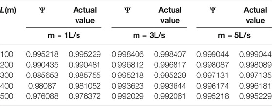
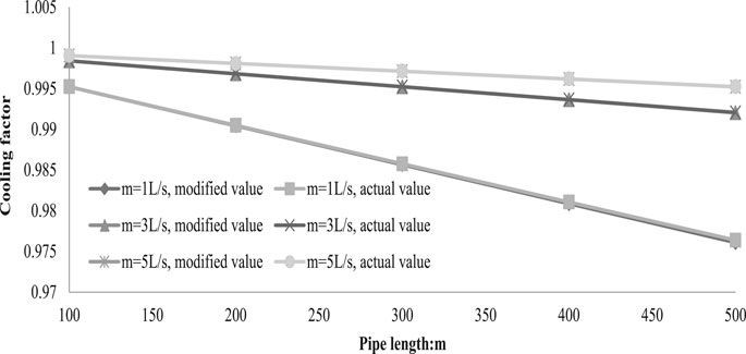
In a heat transfer pipe with a conductivity of 0.2W/(m·K), the comparison between the modified cooling factor and the actual value with different lengths and flow rates is shown in Table 1 and Figure 2. It can be seen that the modified cooling operator proposed here has a high accuracy within hundreds of meters range.
Electrical-Thermal Network Model
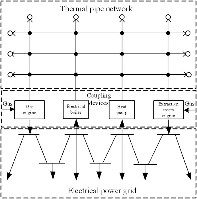
An electrically-thermally hybrid energy supply system, consisting of a electrically power network, a thermal network and electrically-thermally coupled devices, is shown in Figure 3. Thermal power network includes supply network and backwater network, which connect heat source and load and transfer energy with hot water. Electric power network mainly consists of power lines, which transmit active and reactive power in the form of electromagnetic energy. Coupling devices are connected to both the heat network and the electrical power grid to convert other forms of energy into electrical and thermal energy (e.g., gas-fired cogeneration), or to heat with electrical energy (e.g., heat pump, electric boiler, etc.).This section mainly describes their independent mathematical models.
Electrical Power Flow Model
The current vector, network admittance matrix and voltage vector of each node in the electrical power network model satisfy the following equation:
among them, Ii is the current flow of node i, Uk is the voltage vector of node k, Yik is the admittance matrix, and N is the number of nodes in this grid.
In order to obtain the node power equation, (Eq. 12) is rewritten by the equation between node power and current. The equation between node power and current is as follows:
among them, Pi and Qi are the active and reactive power of node i, respectively;
Substituting (Eq. 13) into (Eq. 12) gives:
Rewriting Eq. 14 into the complex domain form and expanding it according to the real and imaginary parts respectively, the active and reactive power of the nodes in vector form can be obtained in Eq. 15:
Thermal Power Flow Model for Heat Network
In a thermal pipe network, according to the principle of flow balance, the net flow in each node's pipeline should be equal to the injected flow at that node, which is:
where mq is the net outflow vector of the nodes, A is the node-branch correlation matrix of the thermal network, and m is the flow variable of each branch.
Meanwhile, in the heat pipe network circuit, the sum of the pressure drop of hot water in an enclosed circuit at the same direction is 0, then:
among them, B is the loop-branch correlation matrix of the heat pipe network, and K is the resistance coefficient matrix of the heat pipe network.
For heat sources or load nodes in a heating network, the heating power is:
where
Substituting (Eq. 16) into (Eq. 18) gives.
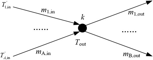
For the hot water mix nodes in the heating pipe network shown in Figure 4, according to the principle of energy conservation, the thermal energy flowing into the node is equal to the thermal energy flowing out of the node. For node k, the energy conservation equation is shown in (Eq. 21):
among them, mi,in and mj,out are respectively the pipeline flow with each incoming branch and the pipeline flow with each outgoing branch.
Applying the temperature relationship in (Eq. 11) to Figure 4 obtains:
where
where
For node i, find node j and pipe k where water flows from node j to node i through pipe k with flow rate mk, Cs and bs can be obtained by the following expressions:
For the backwater network, Cr and br can be obtained by:
Coupling Device Model
Gas Turbine
For gas-turbines, or other gas-fired internal-combustion cogeneration units, the conversion relationship between “fuel-power generation” and “fuel-heating” can be described as:
where
Steam Engine
For steam engines, the conversion relationship between “fuel-electric power generation” and “fuel-heating” can be described as:
where
Heat Pump
For various types of heat pump devices, the thermoelectric ratio is defined to characterize their hotspot conversion relationships:
where
Electric Boiler
An electric boiler is a device that uses electrical energy to make hot water for supply. The heating efficiency is defined to characterize its hotspot conversion relationship:
where
Circulating Pump
Circulating pump is a device that consumes electric power to provide water pressure to the heat pipe network to urge it to circulate heat. It is generally distributed at the outlet of each heat source. Its mathematical model is:
where
Electric-Thermal Network Hybrid Power Flow Calculation Method
Newton-Raphson Algorithm Principle
Newton-Raphson algorithm is a non-linear mathematical method with good convergence and fast iteration speed. It has been widely used in electrical power flow calculation. This paper will extend it to the electric-thermal network mixed power flow calculation. By simultaneously establishing (Eqs. 15, 17, 20, 23, 24), the unified power flow deviation equation of the electric-heat hybrid energy supply network is obtained as:
among them,
Substituting (Eq. 39) into (Eq. 38) and performing Taylor expansion at
Thereby,
Accordingly,
After n iterations, for a given error allowable value
Then the solution
Jacobian Matrix Analysis
In (Eq. 38), the first two equations are the active and reactive power equations of the power system, and the last four equations are the equations of thermal system thermal power, thermal loop pressure, hot water temperature, and return water temperature. Let
where the diagonal elements
among them:
The non-diagonal elements are mainly affected by the electro-thermal coupling device acting as the balance nodes. For
Among them,
Where
For
The subscript “p” denotes the balancing node and k denotes the k-th node associated with the balancing node in the electrical power system.
Similarly, with the aid of operator
Substitute it into (Eq. 44),
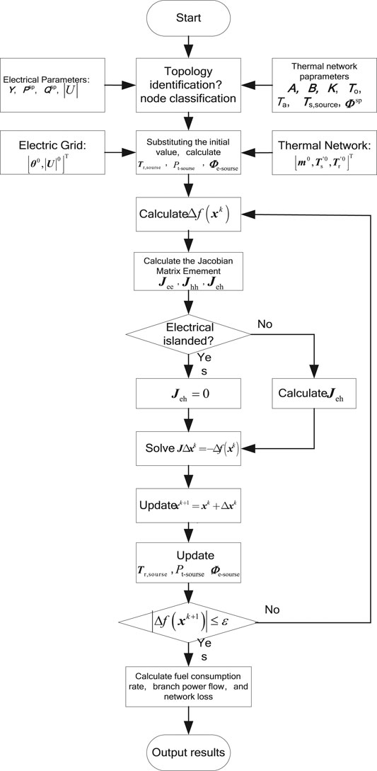
Solving Algorithm Procedure
For power system, nodes are divided into three categories: PQ node, PV node and power balance node. For thermal system, nodes are divided into heat source node, heat load node and heat source balance node. The selection principle and known and unknown quantities in calculation are shown in Table 2.
In an electric-thermal hybrid system, if the power balance node is not coupled with the thermal node and the thermal balance node is not coupled with the electric node, the power grid and the heat network can carry out the power flow solution independently. If the balance node of the electrical power system is coupled with the thermal system but the balance node of the thermal system is not coupled with the power system (e.g. gas or coal-fired boiler), then the power system is solved first, and then the coupled thermal power of the balancing node of the power system is substituted for the thermodynamic system as a given value, and finally the thermal system is solved. If the balance node of power system is not coupled to the thermal system, but the thermal system balance node is coupled to the power system (such as the power system is connected to the grid, the large power grid is used as the balance node, and the thermal system selects the gas unit as the balance node), then the thermal system is solved first to obtain the thermal balance node. The electric power coupled to the power system is used as a given value of the power node of the power system, and finally the power system is solved. In view of the most complex situation, in which the balance node of electrical power system couples to thermal system and also the balance node of thermal system couples to electrical power system, the main steps of hybrid power flow calculation of electric-thermal network are as follows:
(1) Analyze the electric-thermal network system and substitute the known quantity, select the balance node of electrical power system and thermal system, and define the mathematical descriptions of the electric-thermal coupling relationship;
(2) Set the initial iteration value of the state quantities to be determined, calculate the return water temperature of the heat source according to (Eq. 21), calculate the power
(3) Calculate the deviation state function
(4) Calculate each element of the Jacobian matrix;
(5) Solve the state quantities equation
(6) A new state quantity is obtained through
(7) Calculate the return water temperature of the heat source according to (Eq. 21) after iteration, calculate the power of the heat balance node according to (Eq. 49) update, and recalculate the power of the electrical balance node coupling according to (Eq. 52);
(8) Determine whether the latest solution after iteration meets the error range. If not, go back to step 3.
(9) According to the obtained state quantities, the fuel consumption rate, the branch current of the power grid and the loss of the thermal pipeline are calculated according to the content in Section Coupling Device Model.
(10) Output the calculation result.
The corresponding algorithm flow is shown in Figure 5.
Example Analyses
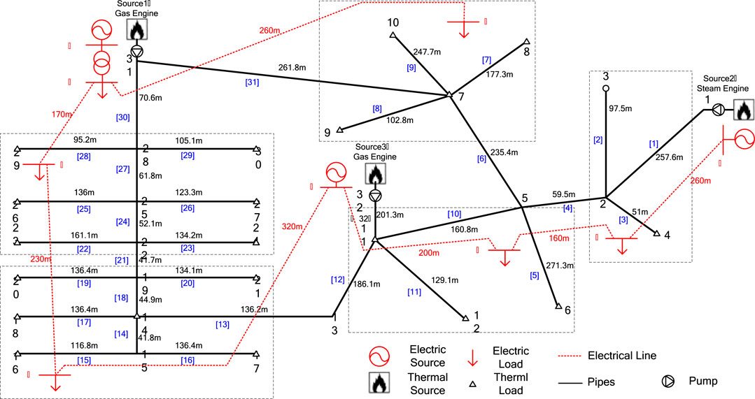
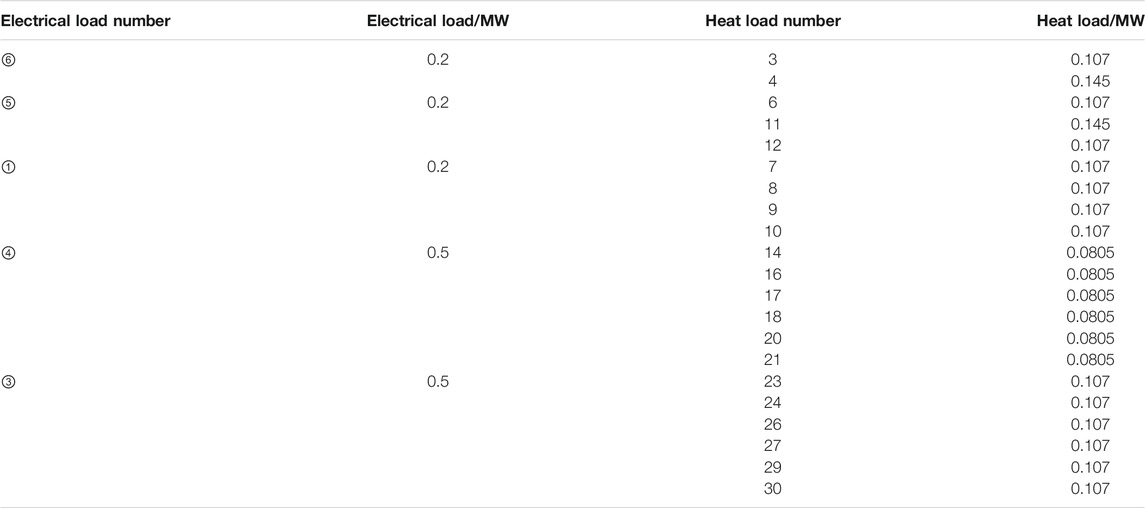
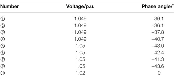
In order to verify the accuracy of the electrical-thermal multi-energy system modeling and power flow calculation method proposed in this paper, an off-grid electric-thermal energy supply system on Barry Island in (Liu et al., 2013) was selected for research. The system supplies energy to several electric and heating loads in five sub-regions. The voltage level of the main electrical power network is 11 kV. Its topology, branch length and numeral identification are shown in Figure 6. This example includes three thermo-electric coupling nodes, namely gas turbine, steam turbine and gas internal combustion engine. The gas turbine outlet voltage is 33 kV, and it is connected to the main power network through a step-down transformer with a capacity of 15 MVA. The steam engine is selected as the balance node of the thermal system, and the gas turbine is used as the balance node of the electrical power system. According to the regional division, the size of the electrical and thermal loads are shown in Table 3. The division and known quantities of each source node are shown in Table 4. The power factor of the power system is 1. Outlet water temperature of each heat load is 30°C. The ambient temperature is 10°C and natural gas has a heat density of 9.7 kW·h/m3.The parameters of thermal lines can be found in (Xing et al., 2012), and those of electrical power lines can be found in Table 5.
Analysis of Simulation Results
Set the initial value of the power angle for the eight unbalanced nodes be 0, the initial value of the voltage amplitude for the six load nodes be 1.05 p.u., the initial value of the flow for the 32 heating network branches be 1L/s, and the initial values of the heating temperature and return water temperature for the 29 thermal loads be 70°C and 30°C, respectively. The error tolerance is 10–3. The results come out after 14 iterations. The simulation is carried out on a computer with Intel (R) core (TM) i5-3210M CPU@2.50 GHz, 4.00G RAM. The solution time of the conventional algorithm and with the modified Sukhov cooling operator is 9.2 and 5.3 s respectively.
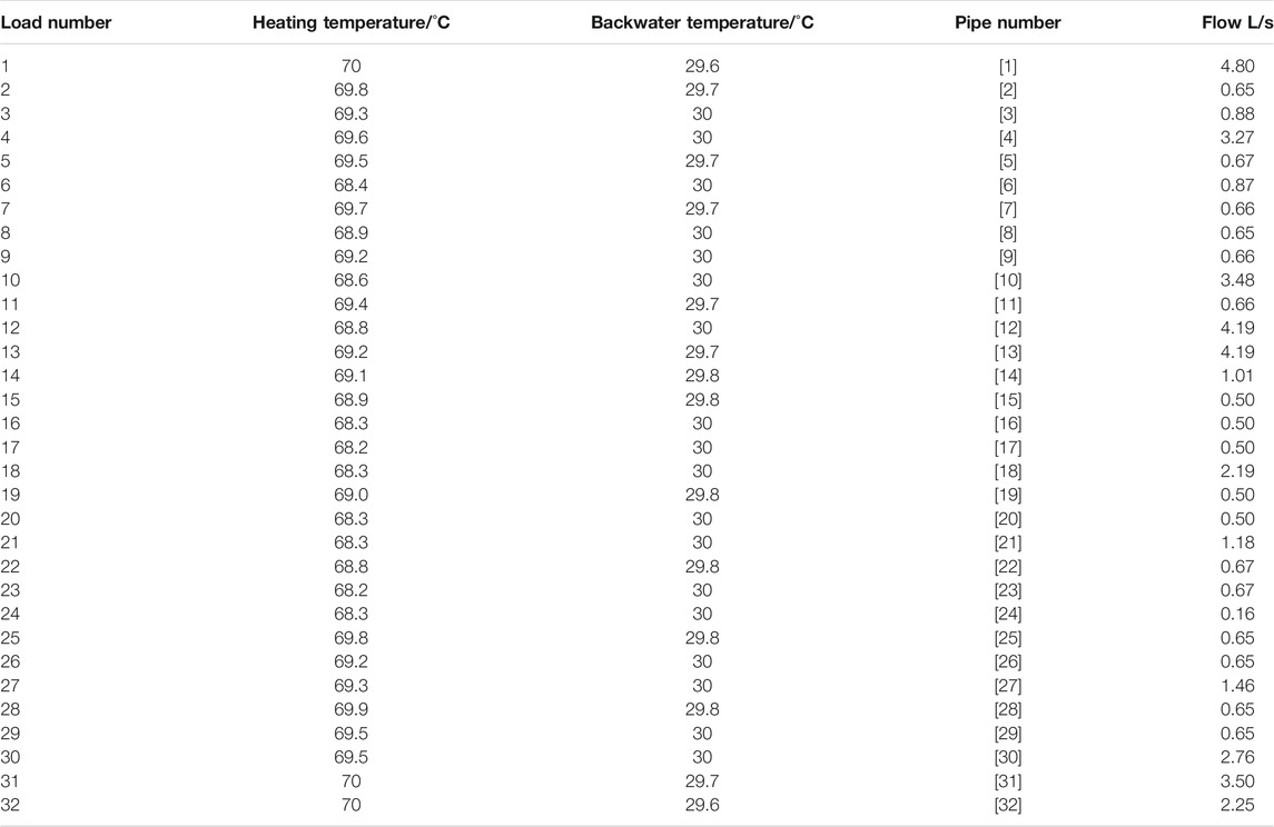
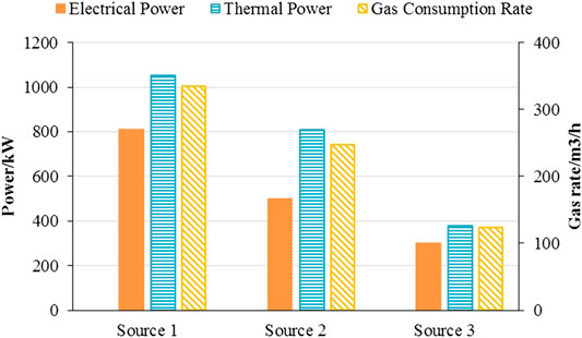
Table 6 shows the solved voltage-phase angle of each node in the electrical power system. It can be found that the voltage drop of each node is small, and there is no voltage exceeding the limit of 1.06 p.u. Table 7 shows the heating temperature and return water temperature of each load node in the thermal system. It can be found that the heating flow rates of source 1 to source 3 are 6.26, 4.81, and 2.25 L/s. Figure 7 shows a comparison of the electro-thermal power and gas consumption rates of the three coupled sources. It can be found that Source 1 has the largest power output in terms of the electro-thermal supply.
Adaptability Analysis
In order to prove the adaptability of this algorithm, the following scenarios are set for analysis based on the above example. Scenario 2: The electrical load remains the same and each thermal load increases by 0.02 MW; Scenario 3: The thermal load remains the same and each electrical load increases by 0.1 MW; Scenario 4: Each electrical load increases by 0.1 MW and each thermal load increases by 0.02 MW. Table 8 shows the calculation results of the algorithm described in this paper in various scenarios. It can be seen that with the electrical load increases, source 1 (the balancing node of the power system) realizes a new electrical-thermal balance through the change of the main active power output; with the thermal load increases, source 2 (the balancing node of the thermal system) contributes the change of the main thermal power output to achieve new electro-thermal balance. When the electric and thermal loads increase, Source 1 and Source 2 respectively lead the power system and thermal system to achieve a new balance. Source 1, as the largest electric and thermal source, undertakes the main power output changes, and a fast solution by this method with modified Sokhov cooling operator can still be achieved.
Loss Analysis
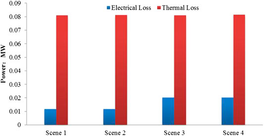
For electricity-heating service providers, how to reduce the losses on the line and pipe network is directly related to the operating efficiency, so it is very important. The loss of the electric heating network in the four scenarios described in Section Adaptability Analysis is shown in Figure 8. It can be found that the transmission loss rate of the heat network is much larger than the transmission loss rate of the power grid. In terms of loss changes, with the increase of the supplied electrical load, the loss of the power network increases significantly, but for the thermal network, the increase of the supplied thermal load does not have a significant effect on the transmission loss of the heat pipe network.
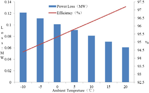
Figure 9 shows transmission loss and transmission efficiency of thermal pipeline networks under different external ambient temperature conditions in scenario 1. It can be found that higher ambient temperature leads to smaller loss in the process of hot water transmission. The lower the ambient temperature, the greater the temperature difference between the hot water and the outside world, the greater the loss of the pipe network and the lower the efficiency of the pipe network, which is consistent with the description of (Eq. 8) in this paper. Therefore, for the heating service, the heating temperature can be appropriately adjusted according to the ambient temperature change to achieve more economical operation.
Conclusion
In this paper, the model of electric-thermal mixed power flow and the model of key equipment of electric-thermal coupling node are constructed. On the basis of deriving the improved Suhof cooling operator for thermal pipeline network, an extended Newton-Raphson algorithm is proposed, and the method of obtaining asymmetric elements in Jacobi matrix is described. The main conclusions are as follows:
(1) The use of the modified Sukhov cooling operator proposed in this paper eliminates the need for exponential operations and helps to achieve fast algorithm convergence during the iteration process.
(2) The electric-thermal coupling equipment of the balance node has a great influence on the power flow calculation and solution of the electric-thermal hybrid system.
(3) The expanded Newton-Raphson power flow algorithm proposed in this paper can better adapt to the solution of strongly coupled multi-quantities.
(4) The electric grid loss is related to the transmission load, and the heat network loss is more directly related to the environmental temperature difference. Optimizing the difference between hot water temperature and ambient temperature is an effective way to achieve the economic operation of the heat network.
Data Availability Statement
The original contributions presented in the study are included in the article/Supplementary Material, further inquiries can be directed to the corresponding author.
Author Contributions
HL proposed the theory. YL deduced the theory. XC verified the theory by developing the example calculation. KJ was responsible for the paper writing. While ZZ provided the simulation. All authors contributed to the article and approved the submitted version.
Conflict of Interest
Author ZZ was employed by Chongqing Shibei Power Supply Company, State Grid Corporation of China.
The remaining authors declare that the research was conducted in the absence of any commercial or financial relationships that could be construed as a potential conflict of interest.
Acknowledgments
This work was supported by grant 2019YFE0111500 from the National key R & D plan of China.
References
Geidl, M., and Andersson, G. (2007). Optimal power flow of multiple energy carriers. IEEE Trans. Power Syst. 22, 145–155. doi:10.1109/TPWRS.2006.888988
Geidl, M. (2007). Integrated modeling and optimization of multi-carrier energy systems. Doctoral Thesis. Swiss Federal Institute of Technology. doi:10.3929/ethz-a-005377890
Good, N., Zhang, L., Navarro-Espinosa, A., and Mancarella, P. (2015). High resolution modeling of multi-energy domestic demand profiles. Appl. Energy 137, 193–210. doi:10.1016/j.apenergy.2014.10.028
He, K. L., Chen, Q., Ma, H., Zhao, T., and Hao, J. H. (2020). An isomorphic multi-energy flow modeling for integrated power and thermal system considering nonlinear heat transfer constraint. Energy 211, 119003. doi:10.1016/j.energy.2020.119003
Huang, W., Zhang, N., Cheng, Y., Yang, J., Wang, Y., and Kang, C. (2020). Multienergy networks analytics: standardized modeling, optimization, and low carbon analysis. Proc. IEEE 108, 1411–1436. doi:10.1109/JPROC.2020.2993787
Kargarian, A., and Rahmani, M. (2015). Multi-microgrid energy systems operation incorporating distribution-interline power flow controller. Elec. Power Syst. Res. 129, 208–216. doi:10.1016/j.epsr.2015.08.015
Kriechbaum, L., Gradl, P., Reichenhauser, R., and Kienberger, T. (2020). Modelling grid constraints in a multi-energy municipal energy system using cumulative exergy consumption minimisation. Energies 13, 3900. doi:10.3390/en13153900
Lingmin, C., Jiekang, W., Fan, W., Huiling, T., and Yan, X. (2020). Energy flow optimization method for multi-energy system oriented to combined cooling, heating and power. Energy 211, 118536. doi:10.1016/j.energy.2020.118536
Liu, X. (2013). Combined analysis of electricity and heat networks. Ph. D. thesis. Cardiff, Wales: Cardiff University.
Liu, X., Wu, J., Jenkins, N., and Bagdanavicius, A. (2016). Combined analysis of electricity and heat networks. Appl. Energy 162, 1238–1250. doi:10.1016/j.apenergy.2015.01.102
Loukarakis, E., and Mancarella, P. (2017). A sequential programming method for multi-energy districts optimal power flow. IEEE Manchester PowerTech 17044946. doi:10.1109/PTC.2017.7980850
Mancarella, P. (2014). MES (multi-energy systems): an overview of concepts and evaluation models. Energy 65, 1–17. doi:10.1016/j.energy.2013.10.041
Moeini-Aghtaie, M., Abbaspour, A., Fotuhi-Firuzabad, M., and Hajipour, E. (2014). A decomposed solution to multiple-energy carriers optimal power flow. IEEE Trans. Power Syst. 29, 707–716. doi:10.1109/TPWRS.2013.2283259
Omalley, M., and Kroposki, B. (2013). Energy comes together: the integration of all systems. IEEE Power Energy Mag. 11, 18–23. doi:10.1109/MPE.2013.2266594
Salpakari, J., Mikkola, J., and Lund, P. D. (2016). Improved flexibility with large-scale variable renewable power in cities through optimal demand side management and power-to-heat conversion. Energy Convers. Manag. 126, 649–661. doi:10.1016/j.enconman.2016.08.041
Shabanpour-Haghighi, A., and Seifi, A. R. (2015). Simultaneous integrated optimal energy flow of electricity, gas, and heat. Energy Convers. Manag. 101, 579–591. doi:10.1016/j.enconman.2015.06.002
Shao, C., Wang, X., Shahidehpour, M., Wang, X., and Wang, B. (2017). An MILP-based optimal power flow in multicarrier energy systems. IEEE Transactions on Sustainable Energy 8, 239–248. doi:10.1109/TSTE.2016.2595486
Wu, F. (2006). Analyses and improves on design method of centralized heating system networks. Harbin, China: Harbin Institute of Technology.
Keywords: sukhov cooling operator, transmission loss, power flow, Newton-Raphson algorithm (NR algorithm), multi-energy system (MES)
Citation: Lei Y, Chen X, Jiang K, Li H and Zou Z (2021) A Novel Methodology for Electric-Thermal Mixed Power Flow Simulation and Transmission Loss Analysis in Multi-Energy Micro-Grids. Front. Energy Res. 8:620259. doi: 10.3389/fenrg.2020.620259
Received: 22 October 2020; Accepted: 10 December 2020;
Published: 09 February 2021.
Edited by:
Shuqing Zhang, Tsinghua University, ChinaReviewed by:
Yizhen Wang, Tianjin University, ChinaHuishi Liang, The University of Sydney, Australia
Hao Tian, University of Alberta, Canada
Copyright © 2021 Lei, Chen, Jiang, Li and Zou. This is an open-access article distributed under the terms of the Creative Commons Attribution License (CC BY). The use, distribution or reproduction in other forums is permitted, provided the original author(s) and the copyright owner(s) are credited and that the original publication in this journal is cited, in accordance with accepted academic practice. No use, distribution or reproduction is permitted which does not comply with these terms.
*Correspondence: Haibo Li, bGloYWlib0B0c2luZ2h1YS1laXJpLm9yZw==
 Yi Lei
 Xiaoyuan Chen
 Keteng Jiang
 Haibo Li
 Zhice Zou3
