 Lei Tao1
 Sen Huang
- 1School of Petroleum Engineering, Changzhou University, Changzhou, China
- 2College of Petroleum Engineering, China University of Petroleum (East China), Qingdao, China
- 3Shandong Ruiheng Xingyu Petroleum Technology Development Co., Ltd., Qingdao, China
- 4School of Petrochemical Engineering, Changzhou University, Changzhou, China
In this paper, viscosity reducers with viscosity reduction ability and foaming ability and the recovery efficiency in N2 huff-n-puff were studied. The optimal 4# viscosity reducer was selected by evaluating the viscosity reduction ability, emulsion stability, interfacial performance, and foaming. The huff-n-puff experiments of single sandpack and dual sandpack were carried out under the reservoir conditions. The results showed that the viscosity reduction rate of 4# viscosity reducer was more than 90% at 50–90°C, and it could form a stable oil/water emulsion when applied to heavy oil. Under the action of 4# viscosity reducer, the interfacial tension between oil and water decreased to 0.41 and 0.19 IFT/mN·m−1 at 50 and 80°C, respectively. In the single sandpack huff-n-puff experiment, the 4# viscosity reducer could inhibit N2 bubbles coalesced in large channels and improve the mobility of heavy oil. Compared with N2 huff-n-puff, the recovery rate of N2 huff-n-puff assisted by 4# increased by 8.53%. In the dual sandpack huff-n-puff experiment, the N2 was inhibited to flow from the low permeability sandpack to the high permeability sandpack by 4# viscosity reducer, and the gas production of the low permeability sandpack increased by 284.71%. Under the combined action of viscosification and plugging, the total oil production of the sandpack increased by 7.88%. Therefore, N2 huff-n-puff assisted by viscosity reducer has a significant effect on enhancing oil recovery in heavy oil reservoirs.
Introduction
With the development of economy, the demand for oil resources is increasing. In the world oil reserves, heavy oil reserves account for more than 70% (Yu, 2001; Zhang et al., 2010). Poor mobility and serious formation heterogeneity are the main reasons for the difficulty of heavy oil development. Thermal recovery is a common method to improve heavy oil recovery. However, due to the energy-intensive emission of a large amount of carbon dioxide, the heavy oil thermal recovery was severely restricted by many countries (De Haan and Van Lookeren, 1969; Hanzlik and Mims, 2003; Ramlal, 2004; Ernandez, 2009). Thus, method of cold recovery of heavy oil has been used in many oil fields. The cold recovery methods of heavy oil mainly include CO2 huff-n-puff and N2 huff-n-puff Alvarado and Manrique, 2010). Carbon dioxide can corrode the pipe networks and tubular columns, and the sources are limited (Dong et al., 2001; Jishun et al., 2015). N2 can be separated from air, is difficult to dissolve in heavy oil, and has higher miscible pressure than CO2. N2 huff-n-puff recovers oil by increasing power of heavy oil with inject N2. Compared to heavy oil thermal recovery, N2 huff-n-puff is an effective heavy oil recovery method, which has low energy consumption and carbon emission (Clancy and Gilchrist, 1983; Hudgins et al., 1990; Zolghadr et al., 2013). Previous studies have found that N2 reached low permeability channels during the first cycle of N2 huff-n-puff and formed foamy oil flow. In the second cycle, the N2 gradually accumulated in the continuous gas phase. In the third cycle, N2 was produced mainly in the form of continuous gas phase. The oil recovery is mainly contributed by first cycle (Ma et al., 2015; Lu et al., 2017).
In view of poor dissolved viscosity reduction ability of N2, serious gas channeling and low recovery rate may occur after multirounds of N2 huff-n-puff. In the process of recovery, viscosity reducer and foam agent were usually applied to assist the heavy oil recovery. The active water film formed on the surface of oil by viscosity reducer, which can reduce the oil–water interfacial tension (IFT), and the O/W emulsion was formed in the near-well area, so as to reduce the viscosity of oil (Allenson et al., 2011). Foam can inhibit gas channeling, which is usual produced in the large channel. Foam has many excellent characteristics, such as blocking large channels firstly, water plugging, and oil defoaming. So foam was widely used in plugging water, profile control, and other aspects (Casteel and Djabbarah, 1985; Dalland and Hanssen, 1995; Hirasaki et al., 2005; Xu et al., 2012; Sun et al., 2016a; Li et al., 2019a; Li et al., 2019b). In order to solve the problems of poor mobility of heavy oil and serious gas channeling in N2 huff-n-puff, a viscosity reduction agent was selected to assist N2 huff-n-puff, which can not only reduce the viscosity of oil but also plug the larger channels.
In this paper, the oil used in the experiments was collected from ChengBei 15-351 reservoir. The four kinds of viscosity reducer were evaluated, including the viscosity reduction ability, emulsion stability, interfacial performance, and foaming. A viscosity reducer with the optimum comprehensive properties was chosen, which can not only reduce the viscosity of oil effectively, but also has good foaming performance. The N2 huff-n-puff experiments were performed to investigate flow behaviors of different permeability levels and the effect of viscosity reducer on oil recovery.
Experimental Equipment and Methods
Experiment Material
In the N2 huff-n-puff experiments, the heavy oil was collected from ChengBei 15-351 well (the properties of oil are shown in Table 1). The rheological properties of heavy oil were measured by high temperature and high pressure rheometer (model MCR302) in this experiment. The specific viscosity and temperature data were shown in Figure 1. Four different viscosity reducers were used in the experiment, labeled as 1#, 2#, 3#, and 4#. Industrial-grade N2 with a purity of 99.99% was used in the experiment. The simulated formation water was composed of a concentration of 10,668 mg/L NaCl and a concentration of 405 mg/L CaCl2. And the sizes of silica sand which was used to simulate the dual sandpack models were 180 and 150 μm.
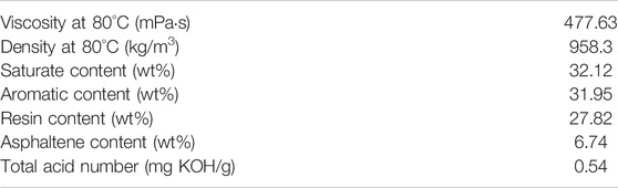
TABLE 1. Properties of oil.
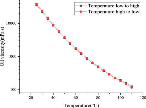
FIGURE 1. Viscosity–temperature curve of heavy oil.
Physical Properties Evaluation Experiment of Viscosity Reducer
Viscosity Reduction Effect Evaluation Experiment
Apparatus: DV2TLV digital viscometer (BROOKFIELD, United States, measure range: 1–6,000,000 cP), magnetic stirrer (XiangTian, China, speed range: <2,400 rpm), thermostatic water bath (XiangTian, China, temperature range: <300°C).
Procedure: The temperature of experiment was measured at 50°C. The 1% viscosity reducer and the heavy oil were put into the thermostatic water bath at 50°C. Firstly, the 48 ml viscosity reducer and 112 ml heavy oil were stirred for 3 min by magnetic stirrer at a constant speed (800 rpm); then the emulsion was left to stand for 6 min. Next, the emulsion was stirred at a speed of 400 rpm for 3 min. Finally, the O/W emulsion was obtained. And the DV2TLV digital viscometer was used to measure the viscosity of the emulsion.
Stability Evaluation Experiment
Apparatus: Magnetic stirrer (XiangTian, China, speed range: range: <2,400 rpm), thermostatic water bath (XiangTian, China, temperature range: <300°C).
Procedure: In this experiment, the stability evaluation parameter SV was measured. The four kinds of prepared heavy oil emulsions were maintained in the thermostatic water bath at 50°C and then the volume of the drained water from emulsion was recorded every 10 min. The water drained rate
In the formula, V1 and V2 refer to the volume of the drained water and the total volume of water in the emulsion, respectively, V2 = 48 ml. Then, the stability
In the formula,
Oil–Water Interfacial Tension Evaluation Experiment
Apparatus: TX-500C rotating IFT apparatus (CNG, Co., United States, speed range: 1,000–10,000 rpm, IFT range: 10−5–10 mN/m, accuracy <± 10−6 mN/m, temperature range: 20–100°C), thermostatic water bath (XiangTian, China, temperature range: <300°C).
Procedure: First of all, the 1% solution of four types of viscosity reducer and two heavy oil samples were prepared. The two heavy oil samples were placed in thermostatic water bath at 50°C and 80°C for 24 h, respectively. Then, the 1% viscosity reducer solution and the heavy oil sample were placed into TX-500C rotating IFT apparatus at a constant speed of 5,000 rpm, and the oil–water IFT at 50 and 80°C was measured.
Foaming Ability Evaluation Experiment
Apparatus: High temperature and high pressure foam evaluation instrument (FoamEvalue, Haian Group, China; pressure range <32 MPa and temperature range <200°C).
Procedure: The 100 ml 1% viscosity reducer solution was placed in the high temperature and high pressure foam evaluation instrument. The liquid height H0 was recorded, and high-pressure N2 was injected until the pressure of the foam evaluation instrument was up to 15 MPa. The temperature was set at 80°C for 60 min. The foam was manufactured at speed of 1,000 rpm for 1 min. The foaming height h1 and liquid height h2 were recorded. Foam half-life t50 was measured which is based on the time required to drain half of the liquid from the foam.
N2 Huff-n-Puff Experiment
Apparatus: The apparatus of the huff-n-puff experiment was described in Figure 2. According to the different experiment requirements, single sandpack and dual sandpack experiment was carried out. A variety of fluids in the experiment were delivered by ISCO pumps (Model 100DX, Teledyne Technologies, United States, flow accuracy <0.25 μl/min, pressure accuracy <±0.5%). The sandpack model had a length of 600 mm and a diameter of 25 mm. Pressure gauges (Haian Group, China, measurement range <50 MPa, accuracy <0.1% FS), pressure sensors (Model 3210PD, Haian Group, China, measurement range <50 MPa, accuracy <0.1% FS), and vacuum gauge (Haian Group, China, measurement range < −0.1 MPa, accuracy <0.1% FS) were used to measure pressure. The electronic balances (Model PL 2002, Mettler Toledo, Switzerland, measurement range <2,100 g, accuracy <0.01 g) were used to measure the weight of produced oil.
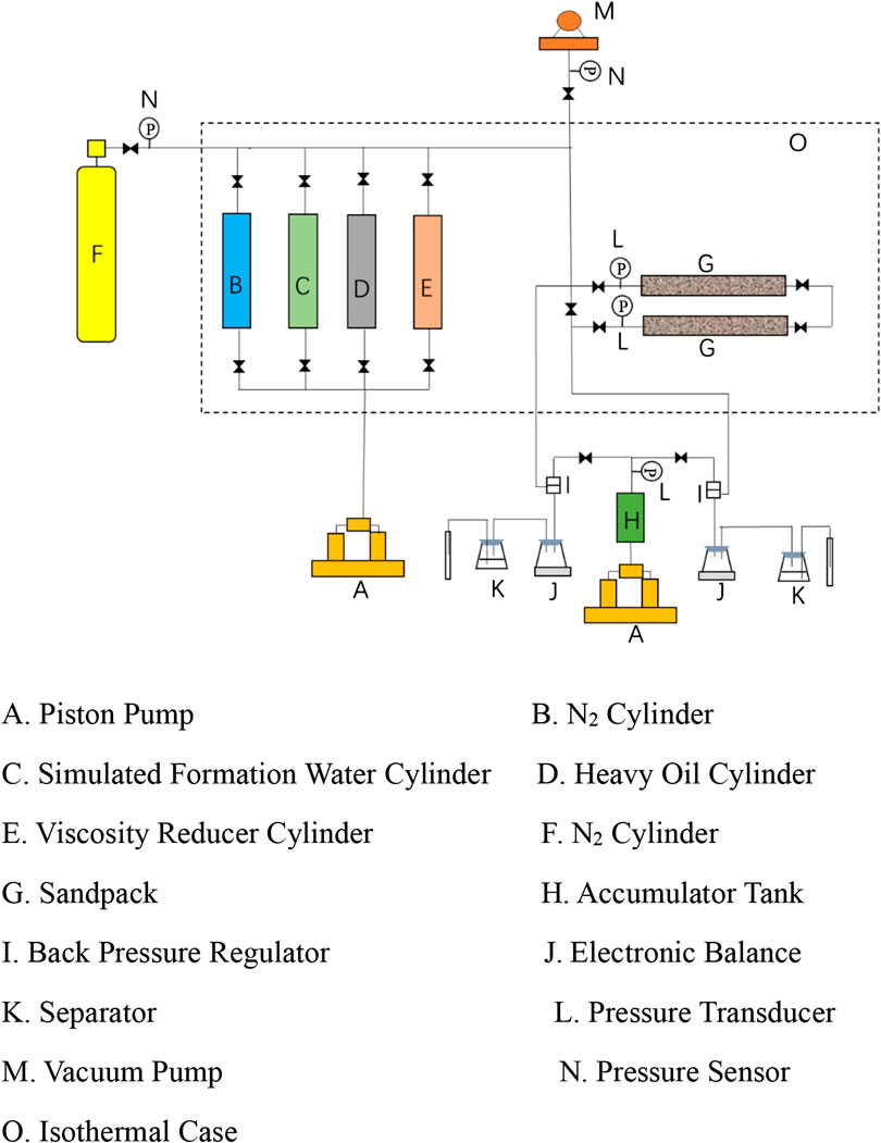
FIGURE 2. Schematic diagram of the huff-n-puff apparatus.
Single sandpack: The experiment procedures for single sandpack were as follows: 1) Silica sand with the same size distribution was used to make sure sandpacks are of similar permeability (2,500–4,000 md). 2) The sandpack was vacuumed for 6 h before being saturated by simulated formation water, and the permeability was measured by the Darcy law. 3) The experimental temperature was maintained at 80°C. The heavy oil was injected into the sandpack with a constant rate of 0.5 ml/min until no water came out at the outlet, and the original oil and water saturations were calculated. 4) The viscosity reducer was pumped into sandpack; then N2 was injected into the sandpack to 15 MPa; the huff process stopped. 5) After 12 h of soak time, the puff process started. 6) The sandpack was opened for a puff process, and the pressure gradually reduced at a rate of 0.2 MPa/min, which was controlled with a backpressure regulator and an ISCO pump at the outlet. The volumes of produced oil and gas were measured. 7) After the pressure at the outlet of first cycle was reduced to zero, the second cycle of the huff process was started and so on (Table 2).
Dual sandpack: The dual sandpack experiment procedures were as follows: 1) Two sandpacks were vacuumed for 6 h. 2) Under reservoir conditions, one sandpack was saturated with the simulated formation water to obtain its pore volume and the permeability of sandpacks was measured by the Darcy law. 3) The experimental temperature was maintained at 80°C. The original oil and water saturations were determined by pumping the heavy oil into the sandpack until no water came out. 4) The viscosity reducer was pumped into sandpack; then N2 was injected into the sandpack to 15 MPa; the puff process stopped. 5) Another sandpack was operated in similar ways, that is, 2), 3), and 4). 6) After 12 h of soak time, the puff process started. 7) The sandpack was opened for a puff process, and the depletion rate of 0.2 MPa/min was controlled with two backpressure regulators and an ISCO pump at the outlet. The weight and volume of produced oil and gas were measured. 8) After the pressure of first cycle was reduced to zero, the second cycle of the huff process was started and so on (Table 2).
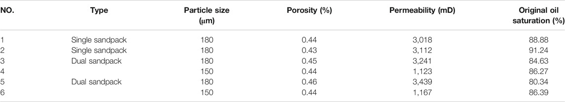
TABLE 2. Sandpack parameters of single sandpack/dual sandpack.
Experiments, Results, and Discussion
Evaluation of Viscosity Reduction Effect
Heavy oil was rich in resin and asphaltene, which results in high density and viscosity of heavy oil. The main reason for the difficulty of heavy oil recovery is poor mobility (Corbett, 1969). Since the viscosity of water was much less than oil, the viscosity of O/W emulsion was less than oil and W/O emulsion. Under the action of viscosity reducer, the mobility of fluid was improved, because the W/O emulsion was transformed into O/W (Kilpatrick, 2012; Liu et al., 2019). According to the experimental procedure and conditions, the experimental results were shown in Tables 3 and 4.
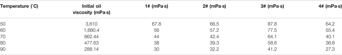
TABLE 3. Experimental data on viscosity reduction effect.
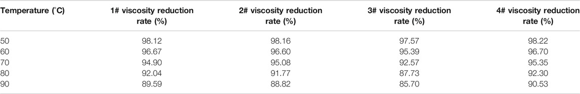
TABLE 4. Experimental data of viscosity reduction rate.
As shown in Table 3, when the temperature was less than 70°C, the viscosity reduction rate of the four viscosity reducers could be more than 90%. Figure 3 shows the viscosity reduction effect of four viscosity reducers. It is observed that the viscosity decreased almost linearly with temperature. In terms of the viscosity reduction effect, 3# has the worst effect. 1#, 2#, and 4# viscosity reducers showed better performances of viscosity reduction effect as compared 3#.
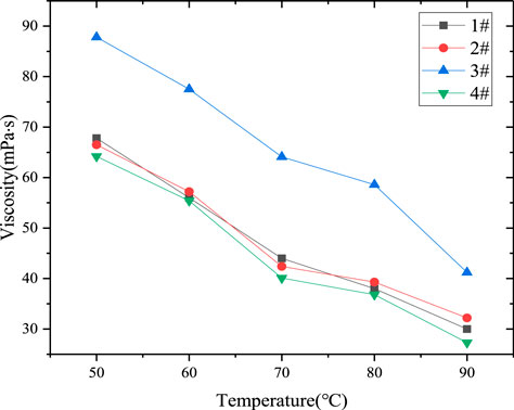
FIGURE 3. Viscosity reduction effect of four viscosity reducers.
Evaluation of Oil–Water Emulsion Stability
Stability was the significant property of heavy oil emulsion, which requires the heavy oil emulsion to remain stable without phase separation and transformation during recovery. The stability of emulsion depends on the strength of oil–water interface. And the viscosity fluctuation of heavy oil O/W emulsion over time depends on its stability (Maneeintr et al., 2013; Yang et al., 2018). The stability of heavy oil emulsion was an important index to evaluate the performance of viscosity reducer. The four kinds of emulsions were prepared and placed in an oven at 50°C. The volume of the drained water was recorded every 10 min (Figure 4). The experimental results were shown in Table 5.
FIGURE 4. The emulsion standing for 1 h.
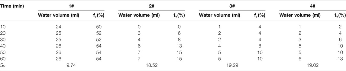
TABLE 5. Experimental results of stability performance of heavy oil emulsion.
The performance of O/W emulsion stability was measured at 50°C. The stability performance of heavy oil emulsion is shown in Figure 5. The volume of water drained from heavy oil emulsion was increased with time. 2#, 3#, and 4# emulsions have good stability performance, in which the volume of water drained emulsions was similar. 1# emulsion drained out 50% water in 5 min; then, the volume of the drained water has no obvious change. After 60 min (Figure 4), all of emulsion was stable; according to
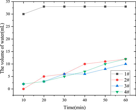
FIGURE 5. Stability performance of heavy oil emulsion.
Evaluation of Oil–Water Interfacial Tension
The oil–water IFT is an important parameter for heavy oil recovery (Sakthivel et al., 2016; Sakthivel et al., 2017). As shown in Figure 6, it is observed that length of oil drop was increased with temperature. Based on the experiment results, shown in Figure 7,the IFT between oil and water was the highest; it reached 6.65 and 6.08 N/m at 50 and 80°C, respectively. Under the action of 4#, the IFT between oil and water decreased to 0.41 and 0.19 IFT/mN·m−1 at 50 and 80°C, respectively. The 4# viscosity reducer was the best at reducing oil–water IFT.
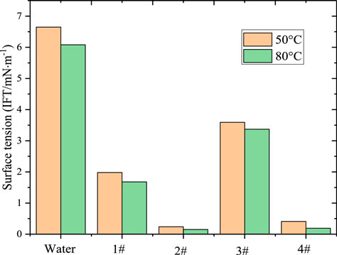
FIGURE 6. Experiment oil–water sample. (A) 50°C. (B) 80°C.
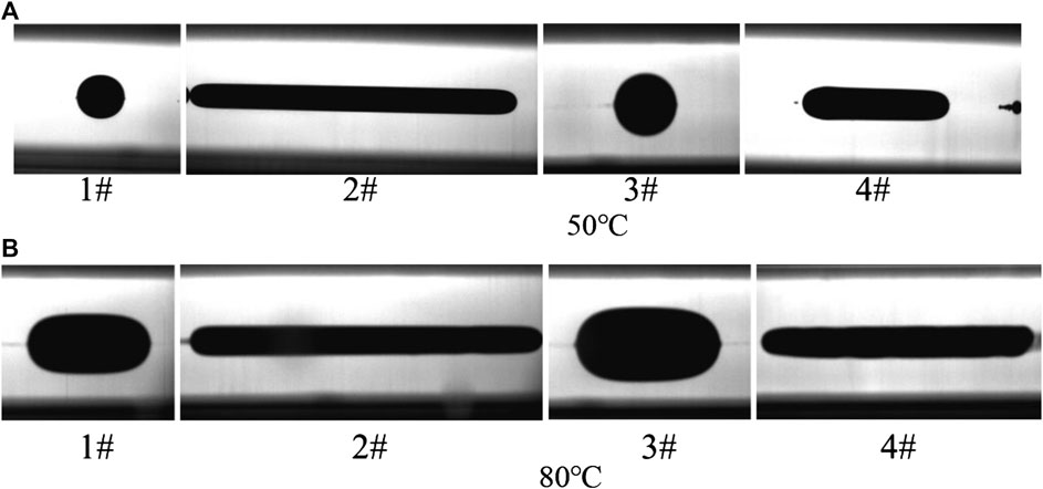
FIGURE 7. Interfacial tension value of heavy oil under the action of viscosity reducer.
Evaluation of Foaming
Foam performance evaluation of viscosity reducer includes foaming ability and drainage half-life (Liu et al., 2010; Sun et al., 2016b). The foaming ability and drainage half-life of four viscosity reducers were measured at 15 MPa and 80°C; the results were shown in Figure 8.
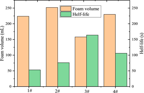
FIGURE 8. Foaming volume and half-life of viscosity reducer.
Figure 9 indicated that the foaming volume of 2# viscosity reducer was the largest, 4# viscosity reducer ranks the second, and that of 3# viscosity reducer was the smallest. However, as for the half-life, the 3# has the longest half-life, 4# ranks the second, and the half-life of the 2# and 1# viscosity reducer was shorter. Although 2# viscosity reducer had the largest foaming volume, its half-life was short; similarly 3# viscosity reducer had the longest half-life, but the foaming volume was small. According to the foaming ability and drainage half-life of four kinds of viscosity reducers, the foaming performance of 4# viscosity reducer was the best.
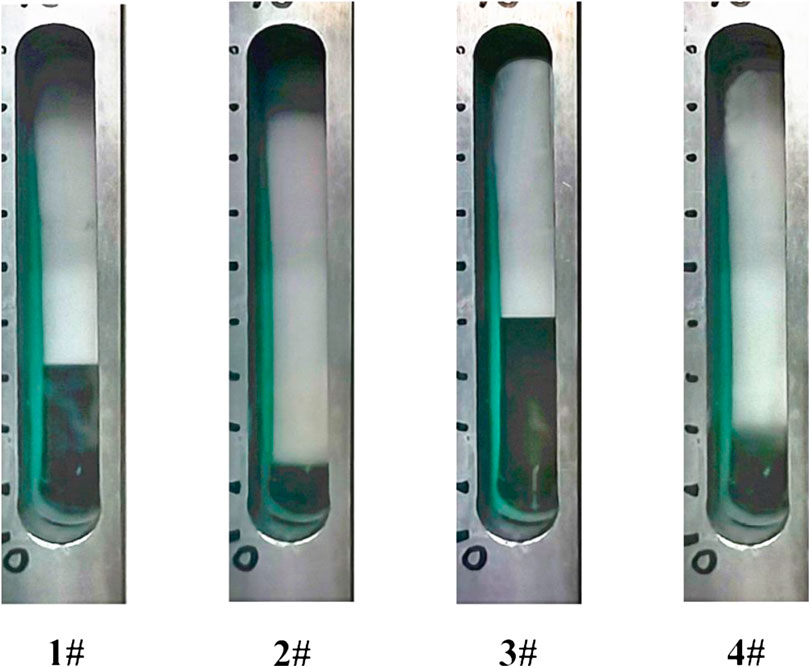
FIGURE 9. Performance evaluation experiment of foaming of viscosity reducer.
By measuring the viscosity reduction ability, emulsion stability, interfacial performance, and foaming ability at different concentrations, the 4# viscosity reducer with best performance was selected to conduct the huff-n-puff experiments.
Results and Analysis of Huff-n-Puff Experiment
Analysis of Oil Production
In the huff-n-puff experiment, the N2 was injected into the sandpack until the pressure increased to 15 MPa, while the soaking time was 12 h. The puff process was started at pressure depletion rate of 0.2 MPa/min. The experimental results are shown in Table 6.
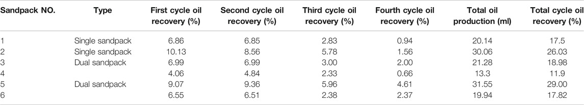
TABLE 6. Results of huff-n-puff experiment.
The oil recovery of N2 huff-n-puff process was shown in Table 6. It can be seen that the oil recovery was mainly concentrated in the first and second cycles. Among them, the oil recovery in the first and second cycles was 6.86 and 6.85%, respectively. And the oil recovery in the third and fourth cycles was only 2.83 and 0.94%, respectively. Therefore, the total recovery of N2 huff-n-puff process was 17.5%.
According to Figure10B, in the N2 huff-n-puff assisted by viscosity reducer experiment, the oil recovery in the first and second cycles was 10.13% and 8.56%, and in the third and fourth cycles was 5.78% and 1.56%, respectively. As shown in Figures 10A,B, it is observed that the recovery performance of the first and second cycles was good. However, with the increase of the cycles, the cumulative oil production decreased rapidly. And the recovery performance of N2 huff-n-puff assisted by viscosity reducer was better than N2 huff-n-puff in each cycle.
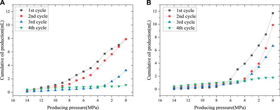
FIGURE 10. Cumulative oil production for each cycle of single sandpack. (A) N2 huff-n-puff. (B) N2 huff-n-puff assisted by viscosity reducer.
In the N2 huff-n-puff of dual sandpack process, the total oil recovery of high permeability sandpack was 18.98% and that of the low permeability sandpack was 11.90%. We note that the permeability of sandpack (NO. 1) and that of sandpack (NO. 3) were similar; however, the oil recovery of sandpack (NO. 3) was increased 1.48%. In the N2 huff-n-puff assisted by viscosity reducer of dual sandpack process, the total oil recovery of high permeability sandpack was 29.00%, and that of the low permeability sandpack was 17.82% Figure 11.
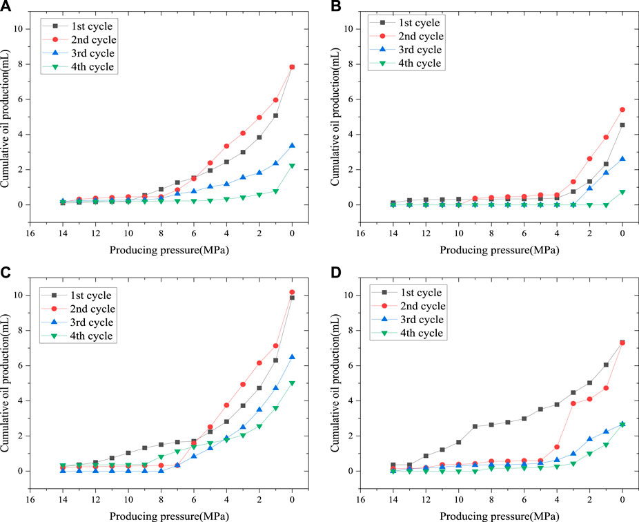
FIGURE 11. Cumulative oil production for each cycle of dual sandpack. (A) High permeability sanpack of N2 huff-n-puff. (B) Low permeability sandpack of N2 huff-n-puff. (C) High permeability sandpack of N2 huff-n-puff assisted by viscosity reducer. (D) Low permeability sandpack of N2 huff-n-puff assisted by viscosity reducer.
Analysis of Gas Production
As shown in Figure 12, with the increase in the huff-n-puff cycles, the gas production increased rapidly. The oil was produced and the oil position in the sandpack was occupied by N2 injection in the next huff process, which increased the gas injection volume in each cycle. In the first and second cycles, when the production pressure was in the range of 8–15 MPa, the gas production per unit pressure drop was relatively flat. And when the production pressure was in the range of 0–6 MPa, the gas production increased per unit pressure drop, which was similar to the oil production. The third and fourth cycle production processes were relatively stable.
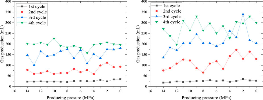
FIGURE 12. Gas production for each cycle of single sandpack. (A) N2 huff-n-puff. (B) N2 huff-n-puff assisted by viscosity reducer.
As shown in Figures 13A,B, the gas production of the high permeability sandpack was higher than that of the low permeability sandpack. This is because the flow resistance of the gas in the high permeability sandpack was less than that in the low permeability sandpack. In the N2 huff-n-puff experiment, the gas production in the first and second cycles was more than that of the third and fourth cycles. In the first and second cycles, one reason is the higher oil saturation in the low permeability sandpack, and the other reason is the effect of the resistance of N2 flowing out in the high permeability sandpack less than that in the low permeability sandpack. In the third and fourth cycles, due to the low oil saturation of the low permeability sandpack, the N2 gas volume was more than the oil in the channel, and the gas was more likely to flow out from the high permeability sandpack.
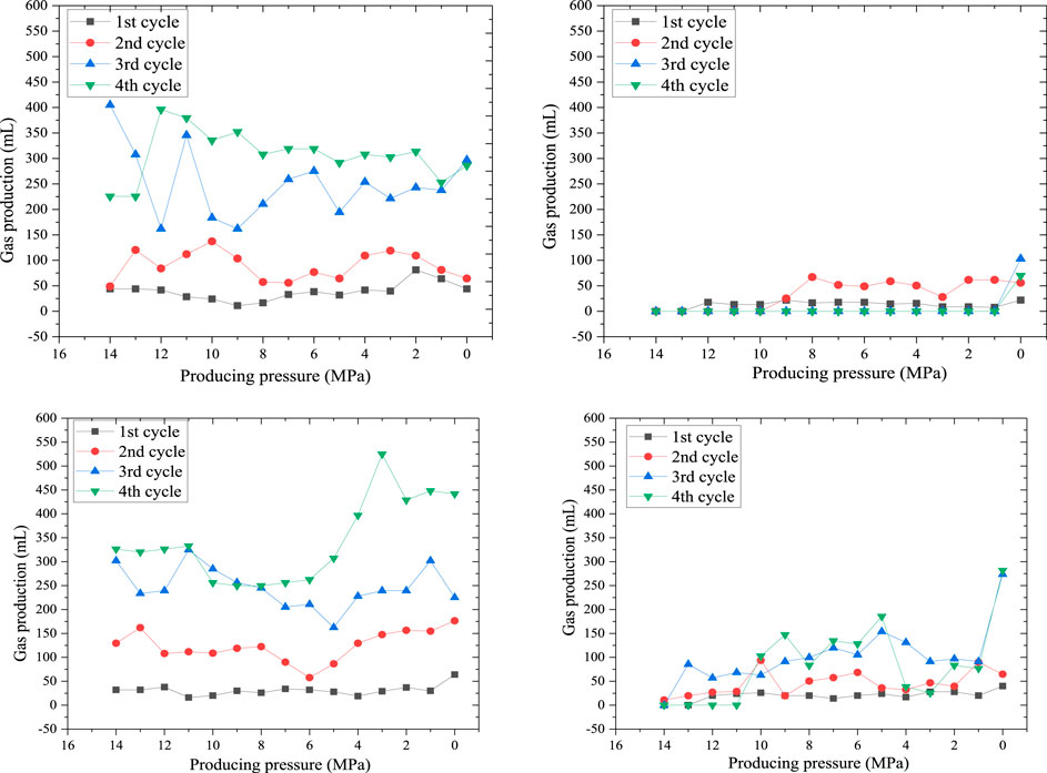
FIGURE 13. Gas production for each cycle of dual sandpack. (A) High permeability sandpack of N2 huff-n-puff. (B) Low permeability sandpack of N2 huff-n-puff. (C) High permeability sandpack of N2 huff-n-puff assisted by viscosity reducer. (D) Low permeability sandpack of N2 huff-n-puff assisted by viscosity reducer.
As shown in Figures 13C,D, in the N2 huff-n-puff assisted by viscosity reducer experiment, the gas production of low permeability sandpack was increased, especially in the third and fourth cycles. This is because of the foaming pugging effect of 4# viscosity reducer. The foam plugged the large channel, which increased the resistance of N2 flow in the channel, but did not affect the N2 displacement of oil (Zhu et al., 1998; Li et al., 2017). Finally, the oil production of low permeability sandpack was improved.
Analysis of Huff-n-Puff Process
In the process of soaking, N2 was dispersed in the pores of the sandpack. This is because of the concentration difference of N2 in the sandpack. By this diffusion way, N2 was almost unaffected by permeability, so N2 can reach the channel with low permeability (Nguyen et al., 2018). In the first cycle (Figure 14), the N2 existed in the sandpack in the form of dispersed small bubbles. In the production process, it was difficult for N2 to form continuous gas phase, and oil of existence enables the sandpack to maintain a high relative permeability. In the process of pressure depletion, the bubbles were expanded to increase the elastic energy of oil. In the second cycle, the large channels in the sandpack were increased as the oil was produced, and the amount of N2 injection increased. The sandpack has continuous gas phase and gas bubbles, the continuous gas phase was usually in the large channel, and the gas bubbles were in the small channel. This kind of continuous gas contributing to the gas bubbles coalesced in the large channel (Adil and Maini, 2005; Zhang et al., 2018). In the third and fourth cycles, the gas bubbles were coalesced, resulting in channeling. After gas channeling, the gas flowed in the large channel with high permeability in the process of production, which led to the failure of N2 to sweep the small channel with high oil saturation and low permeability. The viscous fingering caused by the adverse mobility ratio between the oil and the gas was not a benefit to oil production. When oil was produced, the gas channeling was serious, which was the main reason for low recovery in the third and fourth cycles (Shokri and Babadagli, 2017).
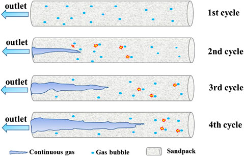
FIGURE 14. Diagram of single sandpack N2 huff-n-puff production process.
In the dual sandpack N2 huff-n-puff experiment (Figure 15), the oil production and gas production of the high permeability sandpack (NO. 3) were higher than those of the low permeability sandpack (NO. 4). However, we found that the remaining oil content of the high permeability sand was higher than that of the low permeability (Figure 16). The main reason for this phenomenon was that the flow resistance of oil and N2 in the high permeability sandpack was lower than that in the low permeability sandpack during the production process. In the process of pressure depletion, the oil and N2 in the low permeability sandpack near the high permeability sandpack could flow to the high permeability sandpack with low resistance. Although the oil in the high permeability sandpack was produced, it was supplemented by the oil which was in the low permeability sandpack. In this case, the remaining oil content of the high permeability sandpack was higher than that of the low permeability sandpack.
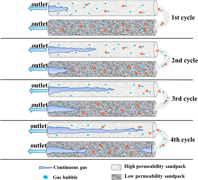
FIGURE 15. Diagram of dual sandpack N2 huff-n-puff production process.
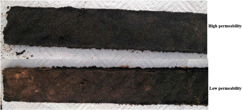
FIGURE 16. Oil sands after huff-n-puff production process.
In the first cycle of dual sandpack N2 huff-n-puff experiment, the oil saturation in the sandpack was high, and the N2 was dispersed in the high permeability and low permeability sandpack. After pressure depletion, in the low permeability sandpack, the oil was drove by the N2 to the high permeability sandpack. The produced oil and N2 in the high permeability sandpack were supplemented by the oil in the low permeability sandpack. As a result, the gas concentration in the high permeability sandpack was increased, and the relative permeability of gas was increased, resulting in the gas channeling. In the second and third cycles, gas channeling became more and more serious in the high permeability sandpack, and the relative permeability of gas in the low permeability sandpack was increased. In the fourth cycle, the N2 saturation increased in dual sandpack, the relative permeability of gas increased significantly, and the relative permeability of oil decreased.
From the above analysis, in the single sandpack N2 huff-n-puff experiment, we can know that the main reason for low oil production was that a large amount of N2 collects in the high permeability channel to form a continuous gas after the second cycle. Continuous gas flows in large channel with low flow resistance and becomes unable to sweep into low permeability channel with high oil content. In addition, with the relative permeability of gas phase increasing, the relative permeability of oil phase decreases. It is indicated that the oil mobility was decreased and gas mobility was increased. In dual sandpack N2 huff-n-puff experiment, the oil and N2 near the high permeability sandpack in the low permeability sandpack flowed to the high permeability sandpack with low flow resistance. However, there were a large number of channels with high permeability in the high permeability sandpack. In the high permeability sandpack, with the supplement of N2, the gas channeling becomes more serious. In order to solve these problems, 4# viscosity reducer with foaming ability was used to assist N2 huff-n-puff, the large channel was plugged by foam to reduce the collection of N2, and the viscosity of oil can be reduced to increase the mobility.
In the process of N2 huff-n-puff experiment, with the reduction of sandpack pressure, N2 was collected in the large channel (Figure 17A), and the continuous N2 tended to flow into large channels. And the oil in small channels with low permeability was difficult to drive. At the same time, because the mobility of oil was lower than that of N2, and the relative permeability of oil decreased continuously, it was difficult for the oil to flow. In order to reduce the collection of N2 in the production process and improve the mobility of oil, the 4# viscosity reducer was used. In the process of N2 flow, the 4# viscosity reducer was stirred and foamed, and the foam plugged the large channel (Figure 17B). The N2 was forced to flow to the small channel by gas, and the gas phase relative permeability was reduced.
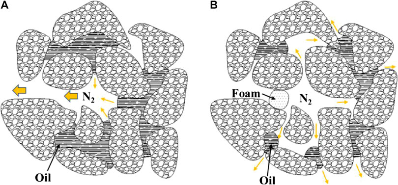
FIGURE 17. Foam plugging process.
In the dual sandpack N2 huff-n-puff assisted by viscosity reducer experiment, the gas production of the low permeability sandpack was obviously increased (Figure 13D). It indicated that the 4# viscosity reducer plugged the large channel in the low permeability sandpack and inhibited the flow of N2 to the high permeability sandpack. The oil production of high permeability sandpack and low permeability sandpack increased by 10.02 and 5.92%, respectively. This is due to the foam of 4# viscosity reducer, which plugged the larger channel, reduced the viscosity of oil, and improved the mobility of oil. The flow of N2 from the low permeability sandpack to the high permeability sandpack was inhibited by foam, while the flow of oil to the high permeability sandpack was difficult to inhibit. There were a large number of high permeability channels in the high permeability sandpack, and the foam inhibited the gas channeling and improved the oil production of the high permeability sandpack. It is the reason that the oil production of the high permeability sandpack is more than that of the low permeability sandpack.
Conclusion
(1) The optimized 4# viscosity reducer has good viscosity decreasing effect, which decreases viscosity rate of oil more than 90% at 50–90°C, which can form stable oil emulsion. The oil–water IFT was 0.41 and 0.19 IFT/mN·m−1 at 50 and 80°C, respectively. What’s more, the 4# viscosity reducer has good foaming ability at high temperature and pressure.
(2) In the single sandpack huff-n-puff experiment, compared with N2 huff-n-puff, the oil recovery rate of N2 huff-n-puff assisted by viscosity reducer increased by 8.53%. In the dual sandpack N2 huff-n-puff experiment, compared with N2 huff-n-puff, oil production of high permeability sandpack of N2 huff-n-puff assisted by viscosity reducer increased by 10.02%, the oil production of low permeability sandpack increased by 5.92%, and total oil production increased by 7.88%.
(3) After the second cycle of single sandpack N2 huff-n-puff experiment, the N2 bubbles coalesced in the large channel, resulting in the gas channeling. In the dual sandpack N2 huff-n-puff experiment, the oil and N2 in the low permeability sandpack, near the high permeability sandpack, flowed to the high permeability sandpack, so the oil production of the high permeability sandpack was increased and the remaining oil was higher than the low permeability sandpack.
(4) The 4# viscosity reducer can reduce the viscosity of oil and plug large channel by foaming. N2 was forced to flow to small channel, which alleviated the generation of continuous gas phase and increased the oil recovery of small channel. In the dual sandpack huff-n-puff experiment, the foam can effectively inhibit the N2 flow from the low permeability sandpack to the high permeability sandpack and increase the N2 displacement efficiency.
Data Availability Statement
The raw data supporting the conclusions of this article will be made available by the authors, without undue reservation.
Author Contributions
The authors LT and SH have equally contributed to this work.
Funding
This work was supported by the Province Key Scientific and Technological Project for the camellia saponin extraction and CO2 saponin foam with high mineralization, China (No. KYCX20_2577).
Conflict of Interest
Author HD was employed by Shandong Ruiheng Xingyu Petroleum Technology Development Co., Ltd.
The remaining authors declare that the research was conducted in the absence of any commercial or financial relationships that could be construed as a potential conflict of interest.
References
Adil, I., and Maini, B. B. (2005). “Role of asphaltene in foamy-oil flow,” in SPE Latin American and caribbean petroleum engineering conference, Rio de Janeiro, Brazil, 20–23 June (Dallas, TX: Society of Petroleum Engineers). doi:10.2118/94786-MS/10.2118/94786-MS
Allenson, S. J., Yen, A. T., and Lang, F. (2011). “Application of emulsion viscosity reducers to lower produced fluid viscosity,” in OTC Brasil, Rio de Janeiro, Brazil, 4–6 October (Offshore Technology Conference). doi:10.4043/22443-MS
Alvarado, V., and Manrique, E. (2010). Enhanced oil recovery: an update review. Energies 3 (9), 1529–1575. doi:10.3390/en3091529
Casteel, J., and Djabbarah, N. (1985). “Sweep improvement in carbon dioxide flooding using foaming agents,” in Annual SPE technical conference Salt Lake City, UT, May 22-25, Vol. 60. Available at:
https://doi.org/10.2118/11848-MSCrossRef Full Text | Google Scholar
Clancy, J.P., and Gilchrist, R.E. (1983). “Nitrogen injection applications emerge in the rockies,” in SPE rocky mountain regional meeting, Salt Lake City, UT, 22–25 May (Dallas, TX: Society of Petroleum Engineers). doi:10.2118/11848-MS
Corbett, L. W. (1969). Composition of asphalt based on generic fractionation, using solvent deasphaltening, elution-adsorption chromatography, and densimetric characterization. Anal. Chem. 41 (4), 576–579. doi:10.1021/ac60273a004
Dalland, M., and Hanssen, J. E. (1995). Foam barriers for thin oil rims: gas blockage with hydrocarbon foams. Geol. Soc. Spec. Publ. 84 (1), 99–109. doi:10.1144/gsl.sp.1995.084.01.11
De Haan, H. J., and Van Lookeren, J. (1969). Early results of the first large-scale steam soak project in the Tia Juana Field, Western Venezuela. J. Petrol. Technol. 21 (1), 101–110. doi:10.2118/1913-pa
Dong, M., Huang, S., Dyer, S. B., and Mourits, F. M. (2001). A comparison of CO2 minimum miscibility pressure determinations for Weyburn crude oil. J. Petrol. Sci. Eng. 31 (1), 13–22. doi:10.1016/s0920-4105(01)00135-8
Ernandez, J. (2009). “EOR projects in Venezuela: past and future,” in ACI optimising EOR strategy 2009, London, UK, 11–12 March 2009, 11–12.
Hanzlik, E., and Mims, D. (2003). “Forty years of steam injection in California-The evolution of heat management,” in SPE international improved oil recovery conference in Asia pacific, Kuala Lumpur, Malaysia October 20‐21, (Dallas, TX: Society of Petroleum Engineers).
Hirasaki, G. J., Miller, C. A., and Pope, G. A. (2005). Surfactant based enhanced oil recovery and foam mobility control. Houston, TX: Rice University.Google Scholar
Hudgins, D. A., Llave, F. M., and Chung, F. T. H. (1990). Nitrogen miscible displacement of light crude oil: a laboratory study. SPE Reserv. Eng. 5 (1), 100–106. doi:10.2118/17372-pa
Jishun, Q., Haishui, H., and Xiaolei, L. (2015). Application and enlightenment of carbon dioxide flooding in the United States of America. Petrol. Explor. Dev. 42 (2), 232–240. doi:10.1016/S1876-3804(15)30010-0
Kilpatrick, P. K. (2012). Water-in-crude oil emulsion stabilization: review and unanswered questions. Energy Fuels 26 (7), 4017–4026. doi:10.1021/ef3003262
Li, B., Zhang, Q., Li, S., and Li, Z. (2017). Enhanced heavy oil recovery via surfactant-assisted CO2 huff-n-puff processes. J. Petrol. Sci. Eng. 159, 25–34. doi:10.1016/j.petrol.2017.09.029
Li, S., Wang, Q., and Li, Z. (2019a). Stability and flow properties of oil-based foam generated by CO2. SPE J. 25 (1), 416–431. doi:10.2118/199339-PA
Li, S., Wang, Q., Zhang, K., and Li, Z. (2019b). Monitoring of CO2 and CO2 oil-based foam flooding processes in fractured low-permeability cores using nuclear magnetic resonance (NMR). Fuel 263, 116648. doi:10.1016/j.fuel.2019.116648
Liu, J., Zhong, L., Yuan, X., Liu, Y., Zou, J., Wang, Q., et al. (2019). Study on the re-emulsification process of water in heavy oil emulsion with addition of water-soluble viscosity reducer solution. Energy Fuels 33 (11), 10852–10860. doi:10.1021/acs.energyfuels.9b02733
Liu, X., Xin, W., Li, G., Zhang, L., Han, Z., and Wang, B. (2010). “Acid-resistant foamer used to control gas Breakthrough for CO2 drive reservoir,” in SPE Asia pacific oil and gas conference and exhibition, Brisbane, Australia, 18–20 October (Dallas, TX: Society of Petroleum Engineers). doi:10.2118/131416-MS
Lu, T., Li, Z., Li, J., Hou, D., and Zhang, D. (2017). Flow behavior of N 2 huff and puff process for enhanced oil recovery in tight oil reservoirs. Sci. Rep. 7 (1), 15695. doi:10.1038/s41598-017-15913-5
Ma, J., Wang, X., Gao, R., Zeng, F., Huang, C., Tontiwachwuthikul, P., et al. (2015). Enhanced light oil recovery from tight formations through CO2 huff ‘n’ puff processes. Fuel 154, 35–44. doi:10.1016/j.fuel.2015.03.029
Maneeintr, K., Sasaki, K., and Sugai, Y. (2013). Investigation of the effects of parameters on viscosities and correlation of heavy oil and stability of its emulsion. J. Jpn. Inst. Energy 92 (9), 900–904. doi:10.3775/jie.92.900
Nguyen, P., Carey, J. W., Viswanathan, H. S., and Porter, M. (2018). Effectiveness of supercritical-CO2 and N2 huff-and-puff methods of enhanced oil recovery in shale fracture networks using microfluidic experiments. Appl. Energy 230, 160–174. doi:10.1016/j.apenergy.2018.08.098
Ramlal, V. (2004). “Enhanced oil recovery by steamflooding in a recent steamflood project, cruse ‘E’field, trinidad,” in SPE/DOE symposium on improved oil recovery, Tulsa, OK, 17-21 April (Dallas, TX: Society of Petroleum Engineers). doi:10.2118/89411-MS
Sakthivel, S., Gardas, R. L., and Sangwai, J. S. (2016). Effect of alkyl ammonium ionic liquids on the interfacial tension of the crude oil–water system and their use for the enhanced oil recovery using ionic liquid-polymer flooding. Energy Fuels 30 (3), 2514–2523. doi:10.1021/acs.energyfuels.5b03014
Sakthivel, S., Velusamy, S., Nair, V. C., Sharma, T., and Sangwai, J. S. (2017). Interfacial tension of crude oil-water system with imidazolium and lactam-based ionic liquids and their evaluation for enhanced oil recovery under high saline environment. Fuel 191, 239–250. doi:10.1016/j.fuel.2016.11.064
Shokri, A. R., and Babadagli, T. (2017). Feasibility assessment of heavy-oil recovery by CO2 injection after cold production with sands: lab-to-field scale modeling considering non-equilibrium foamy oil behavior. Appl. Energy 205, 615–625. doi:10.1016/j.apenergy.2017.08.029
Sun, Q., Zhang, N., Li, Z., and Wang, Y. (2016a). Nanoparticle‐stabilized foam for effective displacement in porous media and enhanced oil recovery. Energy Technol. 4 (9), 1053–1063. doi:10.1002/ente.201600063
Sun, Q., Zhang, N., Li, Z., and Wang, Y. (2016b). Nanoparticle-stabilized foam for mobility control in enhanced oil recovery. Energy Technol. doi:10.1002/ente.201600093
Xu, H. X., Pu, C. S., Yang, H. B., Man, W. H., and Yang, T. (2012). Study on nitrogen foam flooding in fractured reservoir. Adv. Mater. Res. 524–527, 1209–1212. doi:10.4028/www.scientific.net/AMR.524-527.1209
Yang, F., Chen, Y., Sun, G., Yang, S., Li, C., You, J., et al. (2018). Effects of supercritical CO2 treatment on the stability of water-in-heavy-oil emulsion and their mechanisms. Energy Fuels 32 (2), 1358–1364. doi:10.1021/acs.energyfuels.7b03372
Yu, L. (2001). Distribution of world heavy oil reserves and its recovery technologies and future. Spec. Oil Gas Reserv. 8 (2), 98–10. doi:10.3969/j.issn.1006-6535.2001.02.029
Zhang, F., Ouyang, J., Wu, M., Wang, G., and Lin, H. (2010). “Enhancing waterflooding effectiveness of the heavy oil reservoir using the viscosity reducer,” in SPE Asia pacific oil and gas conference and exhibition, Mishref, Kuwait, 11–14 October (Dallas, TX: Society of Petroleum Engineers). doi:10.2118/175312-MS
Zhang, N., Wang, Y., Wang, Y., Yan, B., and Sun, Q. (2018). A locally conservative multiscale finite element method for multiphase flow simulation through heterogeneous and fractured porous media. J. Comput. Appl. Math. 343, 501–519. doi:10.1016/j.cam.2018.05.005
Zhu, T., Strycker, A., Raible, C., and Vineyard, K. (1998). “Foams for mobility control and improved sweep efficiency in gas flooding,” in SPE/DOE improved oil recovery symposium, Tulsa, OK, 19–22 April (Dallas, TX: Society of Petroleum Engineers). doi:10.2118/39680-MS
Keywords: heavy oil, N2 huff-n-puff, viscosity reducer, foaming ability, interfacial tension
Citation: Tao L, Huang S, Liu Y, Cheng H, Du H, Wang C, Zhang N and Li J (2020) Research on Mechanism of Enhancing Recovery of Heavy Oil With N2 Huff-n-Puff Assisted by Viscosity Reducer. Front. Energy Res. 8:601186. doi: 10.3389/fenrg.2020.601186
Received: 31 August 2020; Accepted: 06 October 2020;
Published: 16 November 2020.
Edited by:
Songyan Zhu, China University of Petroleum (Huadong), ChinaReviewed by:
Qian Sun, Chengdu University of Technology, ChinaRenyi Cao, China University of Petroleum, China
Copyright © 2020 Huang, Tao, Liu, Cheng, Du, Wang, Zhang and Li. This is an open-access article distributed under the terms of the Creative Commons Attribution License (CC BY). The use, distribution or reproduction in other forums is permitted, provided the original author(s) and the copyright owner(s) are credited and that the original publication in this journal is cited, in accordance with accepted academic practice. No use, distribution or reproduction is permitted which does not comply with these terms.
*Correspondence: Na Zhang, emhhbmduYTMwMjFAMTI2LmNvbQ==