 Songyan Li
 Zhoujie Wang
 Rui Han2
- 1Key Laboratory of Unconventional Oil & Gas Development (China University of Petroleum (East China)), Ministry of Education, Qingdao, China
- 2School of Petroleum Engineering, China University of Petroleum (East China), Qingdao, China
Normally, the recovery effect of a heavy-oil reservoir gradually deteriorates after multiple rounds of cyclic steam stimulation (CSS). However, the injection of flue gas can effectively increase the utilization degree of steam heat energy, which improves the recovery effect. In this paper, an experimental method for CSS using an energy storage container was established. Based on this method, a one-dimensional core physical simulation experiment for CSS under different flue gas ratios was performed. During the experiment, the changes in temperature field, oil production rate, increase in backpressure, and oil recovery factors were tested. In addition, differences in these data under different injection steam-flue gas ratios were compared. The results show that the flue gas provides a channel of fluids in porous media for steam, which is conducive to the heat transfer of steam to the deeper part of the sandpack. The sandpack has a higher temperature in each cycle than the CSS. The core temperature of each round of flue-gas-assisted CSS is higher than that of the CSS. The final oil recovery factors of flue-gas-assisted CSS using different steam-flue gas ratios are 22.2, 26.7, 30.8, 24.4, and 21.6%, while that of CSS is only 17.2%. According to the experiment, it is concluded that the best steam-flue gas ratio to optimize the flue-gas-assisted CSS is 1:10. With the combined effect of three factors (the temperature field of the sandpack, energizing effect of the flue gas, and degree of oil during recovery), the flue-gas-assisted CSS using the steam-flue gas ratio of 1:10 maximizes the steam heat transfer, increases the energy of return discharge, replenishes formation energy, and improves the oil recovery factor. Through the experiment, the research results provide theoretical guidance for improving the effectiveness of the CSS of heavy-oil reservoirs.
Introduction
With the decreasing reserves of conventional oil reservoirs around the world and increasing oil demand, unconventional oil resources are beginning to attract increasing attention (Nguyen et al., 2018). As one of the unconventional oil reservoirs, heavy oil is extremely rich in reserves. It is estimated that there are approximately 940 billion tons of geological reserves of heavy-oil resources worldwide, which account for 20 percent of the total hydrocarbon resources (Wang et al., 2013; Xu et al., 2013; Zhao et al., 2019). Therefore, the effective development of heavy-oil resources is of great significance to satisfy future energy demands.
Among the technologies to extract heavy-oil reservoirs, the thermal recovery technology is the main development method. Mainly based on steam flooding, cyclic steam stimulation (CSS), and steam-assisted gravity drainage (SAGD), the thermal recovery technology uses technological measures to increase the temperature of the oil layer, reduce the viscosity of heavy oil, and make the heavy oil easily flow to recover the heavy oil (Burkill and Rondon, 1990; Wang et al., 2018a; Li et al., 2019; Chen et al., 2020).
Steam flooding is a technique that continuously injects high-quality steam into the oil layer through an injection well. The oil layer is continuously heated by steam, so that the viscosity of the crude oil in the formation is greatly reduced. In the progress, the injected steam becomes a hot fluid in the formation, which drives the crude oil around the production well and is extracted to the surface (Li et al., 2018; Zhang et al., 2020). The main mechanisms of steam flooding include reducing the viscosity of crude oil, steam distillation, thermal expansion of crude oil, and steam drive (Fan et al., 2019). Currently, steam flooding is a large-scale industrial application of thermal recovery technology, which is an effective method to increase the oil recovery factor after CSS with achieved results (Dong et al., 2019; Du et al., 2019; Wang et al., 2019).
The SAGD technology was first proposed by Butler et al., in 1994. It uses steam as a heat source to realize the convection between steam, oil and water with heat conduction, and it relies on the gravity of crude oil and condensate to extract the heavy oil (Su et al., 2012; Shi et al., 2019; Wang et al., 2019). SAGD can be achieved by two methods: to drill a pair of horizontal wells near the bottom of the reservoir and to drill a horizontal well at the bottom of the reservoir with multiple vertical wells above it. Steam is injected into the oil layer from the upper injection well and moves upward and sideways. Hence, the heated crude oil flows to the production well under the action of gravity. CSS, which injects a certain amount of steam into a heavy-oil production well and subsequently closes its inlet, is an important part in the thermal recovery technology of heavy oil. The closed period is determined by the actual exploitation of heavy oil. After the steam heat has been fully diffused, the wellhead of the production well is opened for heavy-oil production (Tong et al., 2015; Mohsenzadeh et al., 2016; Li et al., 2017).
CSS is mainly a method to increase the production of heavy oil by periodically injecting steam into the oil well to introduce a large amount of heat into the oil layer. The injected heat greatly reduces the viscosity of the crude oil, which improves the fluidity of the crude oil in the oil well and increases production. CSS is a relatively simple and mature steam injection technology for heavy-oil exploitation. It is currently widely used in the United States, Venezuela, and Canada (Huang et al., 2013; Xi et al., 2013; Sun et al., 2015; Li et al., 2020c). With a wide range of reservoir adaptability and fast oil recovery factor, it mainly uses the natural energy of the reservoir for development. Although CSS has achieved good development results in this oilfield block, the heat loss of steam along its injection process is large, the formation pressure rapidly increases, and the bottom hole steam injection pressure is close to or higher than the critical pressure (Song and Yang, 2017; Wei et al., 2017; Wei et al., 2019; Li et al., 2020b; Wan et al., 2020). Moreover, the limited range of steam increases the water cut in the near-wellbore zone, which reduces the heat utilization rate after repeated CSS. Therefore, conventional CSS is not sufficiently ideal to satisfy the efficient economic development of oilfields, so solutions to improve the development effect of CSS are urgently required (Sheng, 2015; Meng and Sheng, 2016; Shilov et al., 2019).
With the development of heavy-oil thermal recovery technology in recent years, increasingly many noncondensable gases such as N2, CO2 and flue gas have been mixed into the conventional CSS process to improve the effectiveness of thermal recovery by steam injection in heavy-oil reservoirs (Ma et al., 2013; Jie et al., 2016; Hu et al., 2017). Under such background, flue-gas-assisted CSS can significantly improve the development effect of CSS, where the flue gas helps to solve the problems in this block. Injecting flue gas in CSS can replenish the formation energy that is lost in the later stage of the CSS on a large scale without significantly reducing the formation temperature (Li and Li, 2016; Chen and Gu, 2017). Simultaneously, the heat-carrying capacity of steam can be enhanced, the direction of steam can be controlled, and the heat exchange process between steam and crude oil in the deep formation can be strengthened to improve the thermal recovery. Therefore, this flooding technology, which utilizes the synergistic effect of N2 and CO2 in the flue gas and steam, can be used as a replacement development method in the later stage of CSS and an independent development method to exploit low- and ultra-low-permeability reservoirs (Bardon et al., 1994; Sahin et al., 2012; Sisakht et al., 2020). Flue gas can increase the formation pressure, dissolve crude oil to expand, reduce the viscosity of heavy oil, reduce the interfacial tension, expand the swept volume, speed up drainage and oil recovery, and expand the heating range; thus, it is conductive to increasing crude oil production and oil layer recovery, reducing exhaust gas emissions, and benefitting environmental protection (Li et al., 2012).
The Junin 4 block in the Orinoco heavy-oil belt in Venezuela was studied in this paper. The viscosity of the heavy oil is approximately 19,000 mPa s at 50°C. The formation water has a pH of 6.71 at 22.4°C, a conductivity of 6.05, a total salinity of 4930.86 mg/L, a Cl− content of 856 mg/L, and an Na+ and K+ content of 1,597 mg/L; the water type is NaHCO3. The average depth of the formation is 345 m, the average porosity is 45.40%, the average permeability is 3,200 mD, the average temperature of the formation is 43°C, and the formation pressure in the middle of the reservoir is 3.4 MPa. The oil reservoir of this block, which has high viscosity, shallow burial depth, and low formation temperature, is difficult for fluid to flow. In addition, there are other problems such as fast heat loss of steam, low steam heat utilization efficiency, low formation pressure, serious formation deficit, insufficient energy in the production process, uneven steam absorption, high oil-water mobility, large differences in degree of spread, and low recovery efficiency (Nnabuihe et al., 2007; Riveros and Barrios, 2011; Ramirez et al., 2018). Therefore, the flue-gas-assisted oil recovery technology was studied for this block in Venezuela to help the flue gas oil recovery technology become gradually matured and perfected to form flue gas oil recovery technology, which effectively improves the recovery rate. This is of great practical significance for delaying the decline in oil field production and promoting the overall coordinated development of oil regions (Wu et al., 2018).
Since flue-gas-assisted CSS is widely used in heavy-oil thermal recovery currently, research on the optimization of the ratio of injected flue gas into steam becomes particularly important (Li and Elsworth, 2019; Xu et al., 2019). However, there are relatively few studies on this aspect, and the relevant mechanism remains unclear. Therefore, it is necessary to conduct research in related fields to find the optimal flue-gas-assisted CSS technology method. In this paper, an experimental method for CSS using an energy storage container was established. On this basis, a one-dimensional core physical simulation experiment of CSS under different flue gas ratio conditions was performed. During the experiment, the temperature field, oil production rate, increase in backpressure, oil recovery factor, etc., were tested to study the characteristics of the production mode and change law of the produced fluid. Furthermore, the production effect of flue-gas-assisted CSS under different steam-flue gas ratios was compared and analyzed to optimize the steam-flue gas ratios and improve the efficiency of heavy-oil production.
Experimental Section
Materials
The oil in the experiment was crude oil from the Junin 4 block in the Orinoco heavy-oil belt in Venezuela. The viscosity of crude oil after dehydration was tested by a rheometer (Model MCR 302, Anton Paar, Austria) to be 19,243 mPa s at 50.0°C and ambient pressure, and the viscosity-temperature curve for the heavy oil in the experiment is shown in Figure 1. In the experiment, both N2 and CO2 had purities of 99.9 mol%, which were provided by Tianyuan, Inc., China. The flue gas in the experiment was obtained by mixing N2 and CO2 at a molar ratio of 0.8701:0.1299. The flue gas composition was simplified in the indoor experiments by considering it a mixture of N2 and CO2. During the process of flue gas configuration, the partial pressure of N2 and CO2 in a certain amount of flue gas was calculated according to Dalton’s law of partial pressure. After calculating the partial pressure, N2 and CO2 were injected into two gas storage tanks of identical volume. After the injection was completed, the pressure of the gas storage tank was the calculated partial pressure. Then, all CO2 in the gas storage tank was transferred to the N2 gas storage tank for mixing to obtain a certain proportion of flue gas. In the experiment, water for making steam was homemade distilled water with a resistivity of 15 MΩ cm. The water for the saturated sandpack was a simulated brine prepared concerning the salinity of the Junin 4 formation water in the Venezuelan target block. The total salinity was 4930.86 mg/L, where the Cl− content was 856 mg/L, and Na+ and K+ were 1,597 mg/L. KCL and NaCl, which were required to prepare the simulated brine, were made with purities of 99.5%, which were provided by Sinopharm Chemical Reagent Co., Ltd. In the experiment, steam was produced by distilled water in a steam generator. The injection temperature of steam was 300°C at the outlet temperature of the on-site steam boiler, and the steam quality was 75%. The sandpack in the experimental model was made of 80 and 120 mesh sand mixed at a ratio of 1:1. The parameters of the sandpacks for the CSS experiments are listed in Table 1, which had almost identical physical parameters and were maintained according to the reservoir conditions. The porosity of these sandpacks is approximately 44.72%, the permeability is approximately 3,133.2 mD, and the original oil saturation is approximately 88.9%.
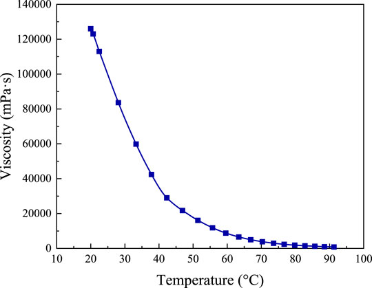
FIGURE 1. Viscosity-temperature curve for heavy oil in the experiment.
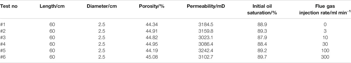
TABLE 1. Sandpack parameters for the CSS experiment.
Apparatus
The schematic diagram of the flue-gas-assisted CSS experimental setup in the laboratory is shown in Figure 2. The flue gas at a specific flow rate was injected into the experimental models by a gas flow controller (model Sla5861, Brooks, United States; flow rate range: 0–350 ml/min under standard conditions; flow accuracy: ±0.5%). Distilled water, which was boosted by a high-precision syringe pump (model 100DX, Teledyne ISCO Company, Teledyne Co., Ltd., USA; flow accuracy: ±0.25 μl/min; pressure accuracy: ±0.5%) was heated into steam by a steam generator (model GL-1, Haian Petroleum Equipment Company; temperature range: 100–350°C; pressure range: 0.1–25 MPa). The flue gas and steam were mixed in the six-way valve and subsequently injected into the sandpack with thermal insulation material (model 304, Nantong Scientific Research Instrument Co., Ltd.; temperature range: 0–300°C; pressure range: 0–40 MPa). By setting the temperature of the heating and insulating jacket (model A1, Nantong Scientific Research Instrument Co., Ltd.; thermal conductivity at room temperature: 0.035 W/M·K − 0.045 W/M·K ± 0.005; heating range: 0–200°C; temperature accuracy: ±0.5°C), the preset oil reservoir temperature required by the sandpack was provided. The temperature was tested by three thermocouples (model K, Nantong Scientific Research Instrument Co., Ltd.; temperature accuracy: ±0.1°C). Then, the temperature data were transmitted to the computer via the thermocouples. The backpressure control device consists of an intermediate container filled with N2 to 2 MPa on the upper part of the piston. During the steam stimulation experiment, the fluid in the sandpack flowed to the lower part of the piston of the intermediate container and was stored in it. When the fluid flowed into the intermediate container, the indication of the pressure gauge increased. When the well was opened, the fluid in the intermediate container flowed back due to the pressure difference. Therefore, the intermediate container plays a role in energy storage.
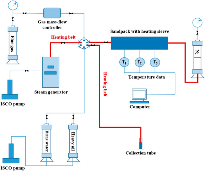
FIGURE 2. Schematic diagram of the flue-gas-assisted steam CSS experimental setup in the laboratory.
Experimental Procedures
(1) The airtightness of the sandpack was tested; then, the sandpack was filled with the prepared mixed sand, and the dry weight of the sandpack was measured;
(2) The sandpack was placed in vacuum for 4 h and subsequently saturated with brine. The weight of the sandpack was tested, and the pore volume was calculated based on the weight difference. The permeability of the sandpack was measured by water flooding according to Darcy equation;
(3) The sandpack was placed in a heating jacket with a preset reservoir temperature of 40°C for 4 h. When a stable temperature was reached, crude oil was injected into the sandpack at a flow rate of 0.5 ml/min for oil saturation. The volume of saturated oil was measured; then, the original oil saturation in the sandpack was calculated using the volume method;
(4) The experimental equipment was installed according to the schematic diagram, and the backpressure was set to 2 MPa. The steam generator was turned on at a temperature of 250°C to preheat. When the temperatures of the sandpack and steam generator became stabilized, the experiment began. According to the experimental design, the steam injection rate was set to 3 ml/min, and the flue gas injection rate-setting parameters are shown in Table 1. The injection time was set to 10 min. The steam injection flow rate was set with the equivalent condensation water, and the gas was set under standard conditions. During the injection process, the fluid in the sandpack flowed to the lower part of the intermediate container piston and was stored in it. After the steam injection was stopped, all valves were closed. The inlet valve was opened after 4 h of simmering the well. The fluid in the intermediate container flowed back, and oil and gas were spit out from the valve until the pressure in the sandpack dropped to the set backpressure, and no fluid flowed out;
(5) During the experiment, the temperature distributed at each temperature measurement point of the sandpack was recorded in real time. The oil production, water production, liquid production, and pressure gauge data were recorded;
(6) We repeated steps (4) and (5) to perform the throughput experiment of the next cycle. When the cumulative recovery rate in the cycle was less than 2%, the experiment was stopped;
(7) The CSS experiment with steam-flue gas ratio of 1:10 was carried out for three times to investigate the repeatability of the results. This minimizes the uncertainty of the experimental observation.
Results and Discussion
Heat Transfer Properties
Since the viscosity of heavy oil is greatly affected by temperature, i.e., an increase in temperature can significantly decrease the viscosity of crude oil, it is extremely important to study the temperature changes during the CSS process for heavy-oil production. Under identical conditions, three cycles of flue-gas-assisted CSS experiments were performed for five different steam-flue gas ratios (1:1, 1:3.3, 1:10, 1:33.3, 1:100), and a set of CSS experiment was performed as a control group. The changes in sandpack temperature for three thermocouples with different steam-flue gas ratios are shown in Figure 3. Thermocouple 1 is 15 cm from the injection end, thermocouple 2 is 30 cm from the injection end, and temperature point 3 is 45 cm from the injection end.
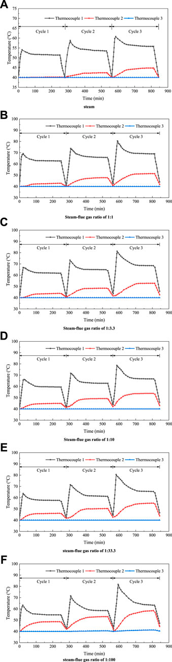
FIGURE 3. Changes in sandpack temperature for three thermocouples with different steam-flue gas ratios. (A) Pure steam. (B) Steam-flue gas ratio of 1:1. (C) Steam-flue gas ratio of 1:3.3. (D) Steam-flue gas ratio of 1:10. (E) Steam-flue gas ratio of 1:33.3. (F) Steam-flue gas ratio of 1:100.
It can be seen from the law of heat transfer that the heat transfer requires the existence of temperature difference as the premise. In other words, in the heat transfer process, the internal energy of a substance determines the temperature of the substance, and the change of internal energy leads to the change of temperature, which can be expressed by Eq. 1.
where Q is heat energy, J; C is the heat capacity, J/(kg·°C); M is the mass, kg; ΔT is the temperature change, °C.
In the process of heat transfer, heat is always transferred by heat conduction, heat convection and thermal radiation. Moreover, two or three heat transfer methods usually occur for transmission, rather than a single one.
Figure 3 shows that the temperature field curves obtained by CSS under different conditions are generally consistent. The temperature of thermocouples 1 and 2 in the first 20 min of each cycle under different steam-flue gas ratio conditions increases with time because the injection of steam increases the temperature of the sandpack. After approximately 20 min, since the heat of the steam continues to be transferred to the far side of the sandpack, the temperature of thermocouple 1 decreases, and that of 2 increases. After the well has been simmered for 4 h, the temperature of each thermocouple tends to be stable. The steam and crude oil have fully exchanged heat, the heat of the steam is fully utilized, and the heat utilization rate is maximal at this time. When the production time increases after the well is opened, the heat carried by the fluid is produced with the production end. Therefore, the overall temperature of the sandpack decreases. At this time, the temperature of the thermocouple gradually decreases and tends to the preset reservoir temperature. However, the temperature of the thermocouples does not completely reduce to 40°C but has a small increase at the end of exploitation, and it increases accordingly with increasing cycle. The reason is that the steam retains some heat in the sandpack after the end of the cycle (Sun et al., 2016; Wang et al., 2018b; Li et al., 2019), which also results in a higher overall temperature in the sandpack after the next cycle of steam injection compared to the previous cycle. The temperature increase of thermocouple 2 is obvious after the end of the simmering well, but it is lower than that of thermocouple 1. The location of thermocouple 3 is not affected because of the limited amount of steam injection, so the temperature has been maintained at the preset reservoir temperature. Thus, the sandpack can simulate the entire reservoir of CSS.
To further analyze the temperature field of flue-gas-assisted CSS under different steam-flue gas ratio conditions, the opening temperatures of three thermocouples in each cycle of different steam-flue gas ratios are compared and shown in Figure 4. The well-opening temperature under different steam-flue gas ratios in the first cycle is observed. For thermocouple 1, the temperature during CSS is the lowest at 51.4°C. After the addition of flue gas of five steam-flue gas ratios, the temperature of thermocouple 1 is 62.7, 61.8, 59.5, 57.6, 54.7°C, i.e., 21.2, 20.2, 15.8, 12.1, 6.4% increases compared to CSS, respectively. The temperature of thermocouple 2 in the first cycle is the lowest (40.2°C) under pure steam conditions. The temperature of thermocouple 2 after the addition of the flue gas of five steam-flue gas ratios is 42.8, 43.8, 44.9, 46.1, and 48.6°C, with temperature increases of 6.5, 9.0, 11.7, 14.7, and 20.9%, respectively. The temperature of thermocouple 3 is basically 40°C with a slight increase under five steam-flue gas ratio conditions.
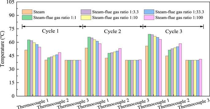
FIGURE 4. Comparison of well-opening temperatures at different steam-flue gas ratios at each cycle for the three thermocouples.
First, the overall temperature of thermocouple 2 is lower than that of thermocouple 1, and thermocouple 3 has the lowest temperature. Since steam does not completely spread to thermocouple 2, the thermocouple 2 has a lower overall temperature than thermocouple 1 after the completion of the simmering well. The location of temperature measurement point 3 is not affected by steam and flue gas, so the temperature has been maintained at the preset reservoir temperature. With the increase in number of cycles, the temperatures of thermocouples 1 and 2 increase to varying degrees, while thermocouple 3 remains at the preset reservoir temperature. Only when the steam-flue gas ratio is 1:100, the flue-gas-assisted CSS has a small temperature increase at thermocouple 3 in the second and third cycles. The principle is that after the previous round of CSS, some of the heat carried by the steam remains in the sandpack, so the temperature increases when the next round of throughput is performed (Li et al., 2017; Dong et al., 2020; Zhao, 2020). Second, when the cycle increases, more gas is trapped in the sandpack, which forms a gas channel. With the increase in number of cycles, the gas channel grows, and the steam flows further in porous media (Zhang et al., 2006; Li et al., 2011; Zhu et al., 2020). Therefore, the internal temperature of the sandpack increases with increasing cycles. During the third cycle, the temperature of thermocouple 1 increases to 69.0, 68.5, 66.7, 65.5, and 63.3°C under five steam-flue gas ratios, and the temperature of CSS also increases to 55.8°C.
In addition, the temperature and heating range of the oil layer after the flue gas mixing are much higher than those of the conventional CSS. Compared with CSS, the temperatures of thermocouples 1 and 2 increase after flue gas was added. The reason is that the flue gas has a strong flow ability, which can open up channels for the steam, reduce the resistance to steam flow in porous media, facilitate heat transfer to the deeper regions and increase the temperature of the sandpack compared to CSS. What’s more, the flue gas forms a gas film on the surface of the well wall, which can inhibit the heat transfer of steam condensation, so that the heat transferred to the rock near the well is reduced. The reduced heat loss enables more heat transfer deeper into the core. The flue gas has a strong heat-carrying and diffusing effect, which effectively increases the heat sweep volume of the steam in the formation (Abedini and Torabi, 2014; Xu et al., 2020). Further observation shows that the temperature increase of thermocouple 1 shows a decreasing trend after flue gas was added, while thermocouple 2 shows an increasing trend. When the steam-flue gas ratio is 1:1–1:100, the well opening temperature at thermocouple 1 in the first cycle gradually decreases, while thermocouple 2 gradually increases. When the steam-flue gas ratio reaches 1:100, the temperatures of thermocouples 1 and 2 were minimal and maximal, respectively. At this time, the temperature field is evenly distributed, and the situation is best.
The principle is that when the proportion of flue gas increases, it is more conducive to the heat transfer of steam to deeper regions (Haskin and Alston, 1989). On one hand, the flue gas forms a gas film on the surface of the well wall, which can inhibit the heat transfer of steam condensation, so that the heat transferred to the rock near the well is reduced. The reduced heat loss enables more heat transfer deeper into the core. On the other hand, the flue gas opens up a channel for the steam, which reduces the resistance of steam flow in porous media and makes it easier for the steam to advance along the gas channel to the core in the next cycle. The heat-carrying capacity of the steam is enhanced, the direction of the steam is controlled, the heat exchange between steam and crude oil is strengthened, and the steam heat is fully utilized (Ma et al., 2015; Xiao et al., 2016; Song and Yang, 2017; Li et al., 2020a; Pang et al., 2020). Therefore, under the combined action of these two aspects, the flue gas can more quickly carry steam at the injection end to the deep part of the model. The steam heat energy is fully utilized, the heat loss along the way is reduced, and the temperature of the deep part of the seepage is increased. When the steam-flue gas ratio is 1:1, although the temperature of the sandpack increases compared to CSS in the presence of flue gas, most of the heat remained trapped at the injection end. Therefore, the temperature at thermocouple 1 is higher than at other steam-flue gas ratios. At this time, the steam heat energy is not fully utilized. In summary, when the steam-flue gas ratio is 1:100, the flue-gas-assisted steam stimulation has the best effect. The reason is that the heat-carrying capacity of the steam can be enhanced when the flue-gas-assisted CSS is performed at this steam-flue gas ratio, and the heat exchange process between steam and crude oil in the depth of the sandpack can be strengthened. Hence, the steam heat energy is maximized.
Oil Production Properties
Figure 5 depicts the changes in oil production rate, liquid production rate, and water cut with time. With the increase in exploitation time in the same cycle, the oil production rate and liquid production rate first increase and subsequently gradually decrease, while the water cut shows an increasing trend during the collection process. Thus, the early stage of each cycle is the main area of oil production. At this time, the liquid production is large, but the oil content is high. When the exploitation time increases, the oil production efficiency decreases, the water cut increases, and the oil recovery effect decreases. When the cycle increases, the maximum fluid production rate decreases. Due to the lower formation energy caused by greater extraction than injection at the end of the previous cycle, the fluid production rate in the next cycle is lower. The oil production rate curve shows that the second cycle has a greater oil production rate than the other cycles. Thus, the main oil production cycle is in the second cycle. In the third cycle, the oil production rate is extremely low, and the water cut of the produced fluid is extremely high. The cumulative recovery rate during this period is less than 2%. The exploitation limit was attained under indoor experimental conditions, and the experiment should be terminated.
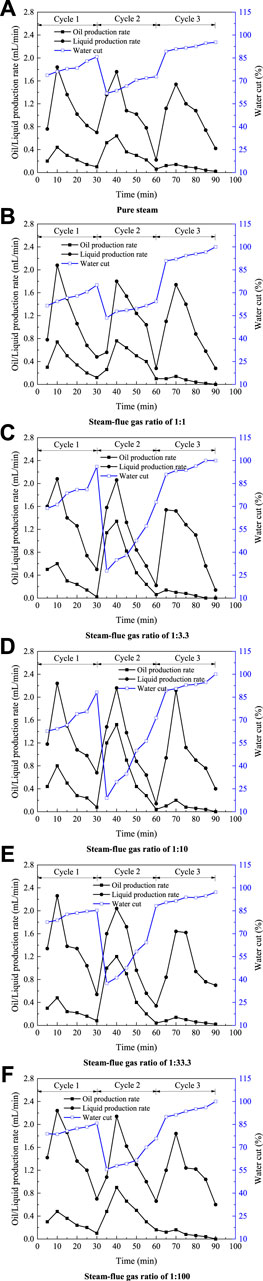
FIGURE 5. Changes in oil production rate, liquid production rate and water cut with time. (A) Pure steam. (B) Steam-flue gas ratio of 1:1. (C) Steam-flue gas ratio of 1:3.3. (D) Steam-flue gas ratio of 1:10. (E) Steam-flue gas ratio of 1:33.3. (F) Steam-flue gas ratio of 1:100.
Oil recovery factor is an important index to measure the level of oilfield development. It refers to the ratio of the amount of oil extracted from the reservoir to the geological reserves within a certain economic limit under modern technological conditions. The formula for oil recovery factor in reservoir development is as the following.
Np is recoverable reserves; N is the original geological reserves.
Figure 6 depicts the changes in backpressure and oil recovery factor with time. The CSS experiment with steam-flue gas ratio of 1:10 was carried out for three times, and the oil recovery factor of the three times was 29.2, 30.8, and 32.1% respectively, with an error range of ±2%. Then, the appropriate one was selected among them. This demonstrates the reproducibility of the experimental results, and minimizes the uncertainty of the experimental observation. This also shows that the experiment follows a certain law of necessity, rather than happens by chance. Thus, the experimental conclusion that follows the objective law must also be reliable and scientific. The curve of the oil recovery factor shows an increasing trend in each cycle. The highest increase in oil recovery factor is observed in the second cycle with a slow increase in the third cycle. The increase in backpressure decreases with the increase in exploitation time in each cycle, and the increase in backpressure decreases to 0 MPa at the end of exploitation. The reason is that the back pressure is increased due to the injection of steam or flue gas into the sandpack at the end of the simmering well. As exploitation progresses, oil and water are produced, and the increase in backpressure decreases. Since the extracted amount during the cycle is greater than the injected amount, the maximum increase in backpressure decreases when the cycle increases. The backpressure increase and oil recovery factor of CSS and flue-gas-assisted CSS generally have similar trends.
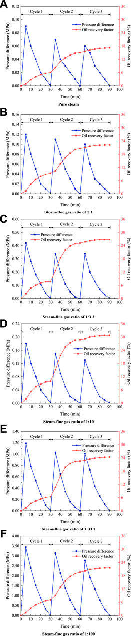
FIGURE 6. Changes in backpressure and oil recovery factor with time. (A) Pure steam. (B) Steam-flue gas ratio of 1:1. (C) Steam-flue gas ratio of 1:3.3. (D) Steam-flue gas ratio of 1:10. (E) Steam-flue gas ratio of 1:33.3. (F) Steam-flue gas ratio of 1:100.
By comparing the injection of pure steam with different proportions of flue gas, we found that the average liquid production rate of CSS was 1.05 ml/min, while it was 1.06, 1.13, 1.14, 1.20, and 1.32 ml/min for different steam-flue gas ratios. The average liquid production rate increases after the addition of flue gas and increases with the increase in proportion of flue gas. It is minimal when the steam-flue gas ratio is 1:1 and maximal when the steam-flue gas ratio is 1:100. The back pressure increase curve shows that the maximum backpressure increase of CSS in the first cycle is 0.09 MPa, while it is 0.12, 0.18, 0.42, 1.19, and 3.44 MPa for different steam-flue gas ratios.
After flue gas was added, the increase in backpressure increases to different degrees. Moreover, the increase in back pressure increases when the proportion of flue gas increases. The principle of this phenomenon is that the flue gas has a large compression coefficient and good expansion, which can maintain the pressure within the corresponding value. It can effectively supplement the reservoir pressure and provide energy for oil and water production (Grogan and Pinczewski, 1987). Therefore, the average liquid production rate and increase in back pressure will increase. The oil production rate curve shows that the average oil production rate under different steam-flue gas ratios is 0.29, 0.34, 0.40, 0.31, 0.28 ml/min. The average oil production rate of CSS is only 0.22 ml/min. The final oil recovery factor and maximum increase in backpressure are observed for different steam-flue gas ratios in Figure 7. The final oil recovery factor is 17.2% when the CSS experiment is performed. When the flue-gas-assisted CSS is performed under different water-to-gas ratios, the final recovery rate is 22.2, 26.7, 30.8, 24.4, and 21.6%, i.e., it increases by 5.0, 9.5, 13.6, 7.2, 4.4, respectively. The addition of flue gas is shown to increase the oil recovery factor. With the increasing proportion of flue gas, the expansion of the flue gas dissolved in the crude oil and low thermal conductivity of the flue gas can increase the heatwave range of the steam. The addition of flue gas effectively reduces the oil-water interfacial tension and improves the microscopic oil washing efficiency during a steam injection (Renner, 1988; Riazi, 1996).
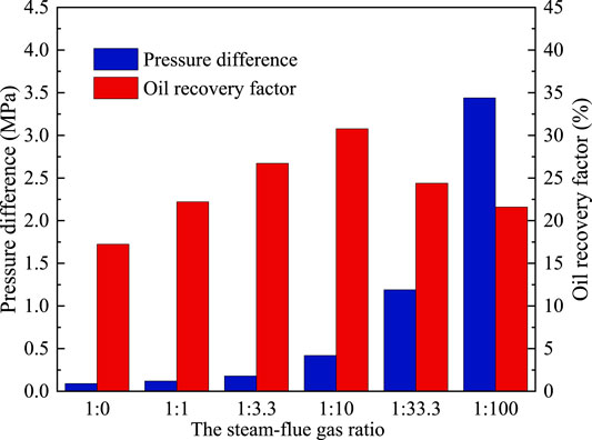
FIGURE 7. Changes in final oil recovery factor and maximum back pressure increase under different steam-flue gas ratios.
Figure 7 shows that the final oil recovery factor increases with the increase in proportion of flue gas in the injection mixture. When the steam-flue gas ratio is 1:10, both quantities reach the maximum value. Afterward, the final oil recovery factor begins to decrease with the increase in flue gas ratio. In other words, a steam-flue gas ratio of 1:10 is most suitable for flue-gas-assisted CSS under the formation conditions.
Thus, there is a threshold amount of effective flue gas injection for the development of flue-gas-assisted CSS, i.e., it is best exploited when the injected steam-flue gas ratio is approximately 1:10.
When the steam-flue gas ratio is 1:1–1:10, oil production is mainly based on the temperature field distribution and pressure energization effects. At this time, when the proportion of flue gas increases, the temperature field is more evenly distributed, and the energy gain due to the effect of the backpressure is larger. Therefore, the final oil recovery factor increases with the increase in flue gas ratio. When the steam-flue gas ratio is 1:10–1:100, oil production is mainly based on the control of mobility during recovery. Heavy oil is produced under the joint action of water and gas. When the proportion of flue gas continues to increase, the overall mobility of water and gas decreases, the oil displacement efficiency decreases, the final oil recovery factor decreases, and the production effect worsens. Under the joint influence of the temperature field, energy increase of backpressure, water and air flow during recovery, the final result is that when the steam-flue gas ratio is 1:10, the flue-gas-assisted CSS has the highest final recovery rate.
Conclusion
(1) By establishing an experimental method of CSS with an energy storage container, a one-dimensional core physical simulation experiment is performed. It is found that the temperature field gradually improves with the increase in flue gas ratio. When the steam-flue gas ratio is 1:100, the flue gas can maximize the heat-carrying capacity of steam, inhibit the condensation heat transfer of steam, open a channel and reduce the resistance for the steam to flow in porous media, which is more conducive to the heat transfer of steam to the deep area and improves the steam heating range.
(2) When the flue-gas-assisted CSS experiment is performed under different steam-flue gas ratios, the maximum increase in backpressure is 0.12, 0.18, 0.42, 1.19, and 3.44 MPa, while the CSS is only 0.09 MPa. After flue gas has been added, the increase in backpressure significantly increases with the increase of flue gas proportion. Thus, flue gas can well replenish the formation of energy and enhance the recovery factor.
(3) The final oil recovery of flue-gas-assisted CSS experiments with different steam-flue gas ratios is 22.2, 26.7, 30.8, 24.4, and 21.6%, while that of CSS is only 17.2%. The oil recovery factor greatly increases with the addition of flue gas. When the steam-flue gas ratio is 1:10, the oil recovery factor is the highest, and the effect of CSS is the best under the joint action of the temperature field, energy increasing effect and mobility during recovery.
Data Availability Statement
The raw data supporting the conclusion of this article will be made available by the authors, without undue reservation.
Author Contributions
SL: Conceptualization, Methodology, Supervision, Funding acquisition. ZW: Investigation, Writing-Original Draft. RH: Investigation.
Funding
This project was financially supported by the National Natural Science Foundation of China (No. 51774306 and No. 51974346), National Key Scientific and Technological Project for the Oil & Gas Field and Coalbed Methane of China (2016ZX05031002-004-002), and the Youth Innovation of University in Shandong Province under (No. 2019KJH002).
Conflict of Interest
The authors declare that the research was conducted in the absence of any commercial or financial relationships that could be construed as a potential conflict of interest.
Acknowledgments
We are grateful to the Shandong Engineering Research Center for Foam Application in Oil and Gas Field Development and UPC—COSL Joint Laboratory on Heavy Oil Recovery for their assistance with the experimental research.
References
Abedini, A., and Torabi, F. (2014). On the CO2, storage potential of cyclic CO2, injection process for enhanced oil recovery. Fuel 124, 14–27. doi:10.1016/j.fuel.2014.01.084
Bardon, C., Corlay, P., Longeron, D., and Miller, B. (1994). CO2 Huff 'n' puff revives shallow light-oil-depleted reservoirs. SPE Reservoir Eng. 9, 92–100. doi:10.2118/22650-pa
Burkill, G. C. C., and Rondon, L. A. (1990). Steam stimulation pilot project in the Orinoco belt, Zuata Area, Venezuela, in SPE Latin America Petroleum Engineering Conference, LAPEC, October 14–19, 1990. Rio de Janeiro, Brazil: Society of Petroleum Engineers. doi:10.2118/21090-ms
Chen, C., and Gu, M. (2017). Investigation of cyclic CO2 huff-and-puff recovery in shale oil reservoirs using reservoir simulation and sensitivity analysis. Fuel 188, 102–111. doi:10.1016/j.fuel.2016.10.006
Chen, H., Wang, Z., Wang, K., Li, Z., and Li, S. (2020). Investigation of EOR mechanism for flue gas assisted SAGD. J. Petrol. Sci. Eng. 193, 107420. doi:10.1016/j.petrol.2020.107420
Dong, X., Liu, H., Chen, Z., Wu, K., Lu, N., and Zhang, Q. (2019). Enhanced oil recovery techniques for heavy oil and oilsands reservoirs after steam injection. Appl. Energy 239, 1190–1211. doi:10.1016/j.apenergy.2019.01.244
Dong, X., Shen, L. W., Golsanami, N., Liu, X., Sun, Y., Wang, F., et al. (2020). How N2 injection improves the hydrocarbon recovery of CO2 HnP: an NMR study on the fluid displacement mechanisms. Fuel 278, 118286. doi:10.1016/j.fuel.2020.118286
Du, Q., Liu, H., Wu, G., Hou, J., Zhou, K., and Liu, Y. (2019). Application of flue-gas foam in thermal-chemical flooding for medium-depth heavy oil reservoirs. Energy Sci. Eng. 7, 2936–2949. doi:10.1002/ese3.471
Fan, J., Jin, B., Yang, J., and Fan, X. (2019). The flue gas-solvent assisted steam assisted gravity drainage studies: experiments and numerical simulation in extra-heavy oil reservoirs,” in Energy sources part a-recovery utilization and environmental effects. Philadelphia, PA: Taylor & Francis Inc doi:10.1080/15567036.2019.1686552
Grogan, A. T., and Pinczewski, W. V. (1987). The role of molecular diffusion processes in tertiary CO2 flooding. J. Petrol. Technol. 39 (05), 591–602. doi:10.2118/12706-pa
Haskin, H. K., and Alston, R. B. (1989). An evaluation of CO2 huff ‘n’ puff tests in Texas. J. Petrol. Technol. 41, 177–184. doi:10.2118/15502-pa
Hu, R., Crawshaw, J. P., Trusler, J. P. M., and Boek, E. S. (2017). Rheology and phase behavior of carbon dioxide and crude oil mixtures. Energy Fuels 31, 5776–5784. doi:10.1021/acs.energyfuels.6b01858
Huang, Y., Liu, D., and Luo, Y. (2013). Research on multiple thermal fluid stimulation for offshore heavy oil production. Spec. Oil Gas Reservoirs 20, 84–86. (in Chinese)
Jie, F., Xiangfang, L., and Weiwei, Z. (2016). Prediction of the productivity of steam assisted gravity drainage using gray relational analysis and BP artificial neural network. J. Comput. Theor. Nanosci. 13, 2838–2842. doi:10.1166/jctn.2016.4626
Li, Z., and Elsworth, D. (2019). Controls of CO2-N2 gas flood ratios on enhanced shale gas recovery and ultimate CO2 sequestration. J. Petrol. Sci. Eng. 179, 1037–1045. doi:10.1016/j.petrol.2019.04.098
Li, S., and Li, Z. (2016). Effect of temperature on the gas/oil relative permeability of Orinoco belt foamy oil. SPE-199339-PA 21, 170–179. doi:10.2118/174089-pa
Li, G., Moridis, G. J., Zhang, K., and Li, X. (2011). The use of huff and puff method in a single horizontal well in gas production from marine gas hydrate deposits in the Shenhu Area of South China Sea. J. Petrol. Sci. Eng. 77, 49–68. doi:10.1016/j.petrol.2011.02.009
Li, S., Li, B., Zhang, Q., Li, Z., and Yang, D. (2018). Effect of CO2 on heavy oil recovery and physical properties in huff-n-puff processes under reservoir conditions. J. Energy Res. Technol. Trans. ASME. 140. doi:10.1115/1.4039325
Li, S., Li, Z., and Sun, X. (2017a). Effect of flue gas and n-hexane on heavy oil properties in steam flooding process. Fuel 187, 84–93. doi:10.1016/j.fuel.2016.09.050
Li, S., Lu, C., Wu, M., Hu, Z., Li, Z., and Wang, Z. (2020a). New insight into CO2 huff-n-puff process for extraheavy oil recovery via viscosity reducer agents: an experimental study. J. CO2 Utili. 42, 101312. doi:10.1016/j.jcou.2020.101312
Li, L., Su, Y., Hao, Y., Zhan, S., Lv, Y., Zhao, Q., and Wang, H. (2019). A comparative study of CO2 and N2 huff-n-puff EOR performance in shale oil production. J. Petrol. Sci. Eng. 181, 106174. doi:10.1016/j.petrol.2019.06.038
Li, X., Wang, Y., Duan, L., Li, G., Zhang, Y., Huang, N., and Chen, D. (2012). Experimental investigation into methane hydrate production during three-dimensional thermal huff and puff. Appl. Energy 94, 48–57. doi:10.1016/j.apenergy.2012.01.024
Li, S., Wang, Q., and Li, Z. (2020b). Stability and flow properties of oil-based foam generated by CO2. SPE J. 25(01), 416–431.doi:10.2118/199339-pa.
Li, S., Wang, Q., Zhang, K., and Li, Z. (2020c). Monitoring of CO2 and CO2 oil-based foam flooding processes in fractured low-permeability cores using nuclear magnetic resonance (NMR). Fuel 263, 116648. doi:10.1016/j.fuel.2019.116648
Li, S., Yu, T., Li, Z., and Zhang, K. (2019). Experimental investigation of nitrogen-assisted SAGD in heavy-oil reservoirs: a two-dimensional visual analysis. Fuel 257, 1–16. doi:10.1016/j.fuel.2019.116013
Li, B., Zhang, Q., Li, S., and Li, Z. (2017b). Enhanced heavy oil recovery via surfactant-assisted CO2 huff-n-puff processes. J. Petrol. Sci. Eng. 159, 25–34. doi:10.1016/j.petrol.2017.09.029
Ma, C., Liu, Y., Lian, P., Wang, C., and Li, J. (2013). Study on steam huff and puff injection parameters of herringbone well in shallow and thin heavy oil reservoir. Open Petrol. Eng. J. 6, 69–75. doi:10.2174/1874834101306010069
Ma, J., Wang, X., Gao, R., Zeng, F., Huang, C., Tontiwachwuthikul, P., and Liang, Z. (2015). Enhanced light oil recovery from tight formations through CO2 huff ‘n’ puff processes. Fuel 154, 35–44. doi:10.1016/j.fuel.2015.03.029
Meng, X., and Sheng, J. J. (2016). Optimization of huff-n-puff gas injection in a shale gas condensate reservoir. J. Unconventional Oil Gas Resources 16, 34–44. doi:10.1016/j.juogr.2016.09.003
Mohsenzadeh, A., Escrochi, M., Afraz, M. V., Karimi, G., Al-Wahaibi, Y., and Ayatollahi, S. (2016). Non-hydrocarbon gas injection followed by steam-gas co-injection for heavy oil recovery enhancement from fractured carbonate reservoirs. J. Petrol. Sci. Eng. 144, 121–130. doi:10.1016/j.petrol.2016.03.003.
Nguyen, P., Carey, J. W., Viswanathan, H. S., and Porter, M. (2018). Effectiveness of supercritical-CO2 and N2 huff-and-puff methods of enhanced oil recovery in shale fracture networks using microfluidic experiments. Appl. Energy 230, 160–174. doi:10.1016/j.apenergy.2018.08.098
Nnabuihe, L., Couzigou, E., Chan, A., and Solana, A. (2007). Technology based formation damage control mitigation measures in the SINCOR Zuata field Venezuela, in Nigeria annual international conference and exhibition 2007, NAICE, August 6–8, 2007. Abuja (Nigeria): Society of Petroleum Engineers. doi:10.2118/111887-ms
Pang, Z., Jiang, Y., Wang, B., Cheng, G., and Yu, X. (2020). Experiments and analysis on development methods for horizontal well cyclic steam stimulation in heavy oil reservoir with edge water. J. Petrol. Sci. Eng. 188, 13. doi:10.1016/j.petrol.2020.106948
Ramirez, A. E., Quevedo, L. D., Ulacio, I. M., and Vasquez, E. M. (2018). Integral analysis of production behavior of horizontal wells associated to the first polymerized water injection pilot project in unconventional reservoir: Zuata principal field, Venezuela, in SPE international heavy oil conference and exhibition 2018, HOCE, December 10–12, 2018. Kuwait City (Kuwait): Society of Petroleum Engineers.
Renner, T. A. (1988). Measurement and correlation of diffusion coefficients for CO2 and rich-gas applications. SPE Reservoir Eng. 3 (02), 517–523.doi:10.2118/15391-pa
Riazi, M. R. (1996). A new method for experimental measurement of diffusion coefficients in reservoir fluids. J. Petrol. Sci. Eng. 14 (3–4), 235–250.doi:10.1016/0920-4105(95)00035-6.
Riveros, G. V., and Barrios, H. (2011). Steam injection experiences in heavy and extra-heavy oil fields Venezuela, SPE international heavy oil conference and exhibition 2011, HOCE 2011, December 12–14, 2011. Kuwait City (Kuwait): Society of Petroleum Engineers, 265–279.
Sahin, S., Kalfa, U., and Celebioglu, D. (2012). Unique CO2-injection experience in the Bati Raman field may lead to a proposal of EOR/sequestration CO2 network in the Middle East. SPE-139616-PA 4, 42–50. doi:10.2118/139616-pa
Sheng, J. J. (2015). Increase liquid oil production by huff-n-puff of produced gas in shale gas condensate reservoirs. J. Unconventional Oil Gas Resources 11, 19–26. doi:10.1016/j.juogr.2015.04.004
Shi, X., Jiang, X., Chen, F., Lu, S., He, N., and Liu, L. (2019). Reservoir selection evaluation and application of flue gas-assisted gravity drainage technique. Petrol. Geol. Recovery Efficiency 26, 93–98.
Shilov, E., Cheremisin, A., Maksakov, K., and Kharlanov, S. (2019). Huff-n-puff experimental studies of CO2 with heavy oil. Energies 12. doi:10.3390/en12224308
Sisakht, N. N., Rouzbahani, M. M., Karbasi, A., Zarinabadi, S., and Sabzalipour, S. (2020). CO2 chemical absorption from fluid catalytic cracking unit flue gases of Abadan Oil Refinery in Iran, using diethanolamine solvent. Environ. Sci. Pollut. Control Ser. 27, 25312–25326. doi:10.1007/s11356-020-08708-1
Song, C., and Yang, D. (2017). Experimental and numerical evaluation of CO2 huff-n-puff processes in Bakken formation. Fuel 190, 145–162. doi:10.1016/j.fuel.2016.11.041
Su, Z., Moridis, G. J., Zhang, K., and Wu, N. (2012). A huff-and-puff production of gas hydrate deposits in Shenhu area of South China Sea through a vertical well. J. Petrol. Sci. Eng. 86–87, 54–61. doi:10.1016/j.petrol.2012.03.020
Sun, J., Zou, A., Sotelo, E., and Schechter, D. (2016). Numerical simulation of CO2 huff-n-puff in complex fracture networks of unconventional liquid reservoirs. J. Nat. Gas Sci. Eng. 31, 481–492. doi:10.1016/j.jngse.2016.03.032
Sun, X., Li, Z., Li, S., and Yang, Y. (2015). Performance of reducing surface tension by adding flue gas and solvent in SAGD process. J. Central South Univ. Sci. Technol. 46, 324–331. (in Chinese)
Tong, L., Zhang, G., and Kang, A. (2015). Experiment of steam stimulation effect improved by different assisted methods and its numerical simulation. Petrol. Geol. Recovery Efficiency 22, 93–97. (in Chinese)
Wan, T., Wang, X., Jing, Z., and Gao, Y. (2020). Gas injection assisted steam huff-n-puff process for oil recovery from deep heavy oil reservoirs with low-permeability. J. Petrol. Sci. Eng. 185, 106613. doi:10.1016/j.petrol.2019.106613
Wang, X., Wang, J., and Qiao, M. (2013). Horizontal well, nitrogen and viscosity reducer assisted steam huff and puff technology: taking super heavy oil in shallow and thin beds, Chunfeng Oilfield, Junggar Basin, NW China, as an example. Petrol. Explor. Dev. 40, 104–110. doi:10.1016/s1876-3804(13)60010-5
Wang, Y., Hou, J., Song, Z., Yuan, D., Zhang, J., and Zhao, T. (2018a). A case study on simulation of in-situ CO2 huff- ‘n’-puff process. SPE-176327-PA 21, 109–121. doi:10.2118/176327-pa
Wang, Y., Ren, S., Zhang, L., Peng, X., Pei, S., Cui, G., and Liu, Y. (2018b). Numerical study of air assisted cyclic steam stimulation process for heavy oil reservoirs: recovery performance and energy efficiency analysis. Fuel 211, 471–483. doi:10.1016/j.fuel.2017.09.079
Wang, Y., Ren, S., Zhang, L., Deng, J., Gong, Z., and Hu, C. (2019a). Experimental investigation and field pilot testing of air assisted cyclic steam stimulation technique for enhanced heavy oil recovery. Int. J. Oil Gas Coal Technol. 21, 407–434. doi:10.1504/ijogct.2019.101471
Wang, Z., Li, Z., Sarma, H. K., Xu, Y., Wu, P., Yang, J., Wang, H., and Lu, T. (2019b). A visualization experimental study on gas penetration through interlayer to improve SAGD performance. J. Petrol. Sci. Eng. 177, 959–970. doi:10.1016/j.petrol.2019.03.001
Wei, B., Pang, S., Pu, W., Lu, L., Wang, C., and Kong, L. (2017). “Mechanisms of N2 and CO2 assisted steam huff-n-puff process in enhancing heavy oil recovery: a case study using experimental and numerical simulation,” in SPE Middle East oil and gas show and conference 2017, March 6–9, 2017. Manama (Bahrain): Society of Petroleum Engineers (SPE), 1597–1608.
Wei, B., Zhang, X., Wu, R., Zou, P., Gao, K., Xu, X., Pu, W., and Wood, C. (2019). Pore-scale monitoring of CO2 and N2 flooding processes in a tight formation under reservoir conditions using nuclear magnetic resonance (NMR): a case study. Fuel 246, 34–41. doi:10.1016/j.fuel.2019.02.103
Wu, Z., Liu, H., Zhang, Z., and Wang, X. (2018). A novel model and sensitive analysis for productivity estimate of nitrogen assisted cyclic steam stimulation in a vertical well. Int. J. Heat Mass Tran. 126, 391–400. doi:10.1016/j.ijheatmasstransfer.2018.05.025
Xi, C., Guan, W., Jiang, Y., Liang, J., Zhou, Y., Wu, J., et al. (2013). Numerical simulation of fire flooding for heavy oil reservoirs after steam injection: a case study on Block H1 of Xinjiang Oilfield, NW China. Petrol. Explor. Dev. 40, 766–773. doi:10.1016/s1876-3804(13)60102-0
Xiao, P., Yang, Z., Wang, X., Xiao, H., and Wang, X. (2016). Experimental investigation on CO2, injection in the Daqing extra/ultra-low permeability reservoir. J. Petrol. Sci. Eng. 149, 765–771. doi:10.1016/j.petrol.2016.11.020
Xu, A., Mu, L., Fan, Z., Wu, X., Zhao, L., Bo, B., and Xu, T. (2013). Mechanism of heavy oil recovery by cyclic superheated steam stimulation. J. Petrol. Sci. Eng. 111, 197–207. doi:10.1016/j.petrol.2013.09.007
Xu, Z., Li, B., Zhao, H., He, L., Liu, Z., Chen, D., et al. (2020). Investigation of the effect of nanoparticle-stabilized foam on EOR: nitrogen foam and methane foam. ACS Omega 5, 19092–19103. doi:10.1021/acsomega.0c02434
Xu, Z., Li, Z., Jing, A., Meng, F., Dang, F., and Lu, T. (2019). Synthesis of magnetic graphene oxide (MGO) and auxiliary microwaves to enhance oil recovery. Energy Fuels 33 (10), 9585–9595. doi:10.1021/acs.energyfuels.9b01841
Zhang, H., Liu, Y., Ta, Y., and Zou, F. (2020). Physical simulation experiment of flue gas-assisted SAGD in super heavy oil reservoir. Fault-Block Oil Gas Field 27, 244–247. (in Chinese)
Zhang, Y. P., Sayegh, S. G., Huang, S., and Dong, M. (2006). Laboratory investigation of enhanced light-oil recovery by CO2/flue gas huff-n-puff process. PETSOC- 45, 24–32. (in Chinese)
Zhao, Q., Li, Z., Wang, S., Lai, F., and Li, H. (2019). Phase behavior measurements and modeling for N2/CO2/extra heavy oil mixtures at elevated temperatures. Ind. Eng. Chem. Res. 58, 428–439. doi:10.1021/acs.iecr.8b03945
Zhao, Y. (2020). Laboratory experiment and field application of high pressure and high quality steam flooding. J. Petrol. Sci. Eng., 189. doi:10.1016/j.petrol.2020.107016
Keywords: flue gas, cyclic steam stimulation, heat transfer, oil recovery factor, physical simulation
Citation: Li S, Wang Z, Han R, Wang L and Hu Z (2020) Experimental Study on the Cyclic Steam Stimulation Assisted by Flue Gas Under Shallow Heavy-Oil Reservoir Conditions: Optimization of the Steam-Flue Gas Ratio. Front. Energy Res. 8:599370. doi: 10.3389/fenrg.2020.599370
Received: 27 August 2020; Accepted: 27 October 2020;
Published: 30 November 2020.
Edited by:
Kalpit V. Shah, RMIT University, AustraliaReviewed by:
Ahmet Arısoy, Istanbul Technical University, TurkeyHari Vuthaluru, Curtin University, Australia
Alireza Bahadori, Oil and Gas Center, China
Copyright © 2020 Li, Wang, Han, Wang and Hu. This is an open-access article distributed under the terms of the Creative Commons Attribution License (CC BY). The use, distribution or reproduction in other forums is permitted, provided the original author(s) and the copyright owner(s) are credited and that the original publication in this journal is cited, in accordance with accepted academic practice. No use, distribution or reproduction is permitted which does not comply with these terms.
*Correspondence: Songyan Li, bHN5dXBjQDE2My5jb20=