
95% of researchers rate our articles as excellent or good
Learn more about the work of our research integrity team to safeguard the quality of each article we publish.
Find out more
ORIGINAL RESEARCH article
Front. Energy Res. , 30 October 2020
Sec. Advanced Clean Fuel Technologies
Volume 8 - 2020 | https://doi.org/10.3389/fenrg.2020.592142
This article is part of the Research Topic Low-Carbon Technologies for the Petroleum Industry View all 19 articles
Steam injection is an important process for the thermal recovery of heavy oil reservoirs. As a non-condensable gas CO2-assisted steam injection can not only improve the development effect but also reduce carbon emissions. In this study, the simulation method was combined with the experimental method. Based on an experiment using steam condensation with or without CO2, the influence of the condensation mode on steam heat transfer was considered. The effect of changes in the steam flow rate on phase transition and steam quality were analyzed. The heat transfer effects of the gas-steam mixture with different contents of CO2 were compared. The results show that the surface condensation mode changes from dropwise condensation to film condensation with the addition of CO2, and the average temperature of the condensation block decreases by 20.05%. With increases in the steam flow rate, the quality of steam increases, and the heat transfer coefficient of steam on the condensation surface increases. With increase in CO2 content, the temperature of the gas-steam mixture decreases, and the inhibition effect on steam heat transfer is more obvious.
The development of heavy oil reservoirs is at a stage of high energy consumption and high cost. The green and efficient development of heavy oil resources strongly relies on breakthroughs in related theories and technological innovations. At present, thermal oil recovery, including steam flooding, steam huff and puff, SAGD, etc., are commonly used. However, the economic benefits of these development methods are often poor, with issues such as high steam loss, low effective heat, and a large number of greenhouse gases produced in the process (Lawal, 2014; Zhang et al., 2018; Xu et al., 2020a). New methods developed for the recovery of heavy oil reservoirs may, in some cases, be an economically viable alternative to steam (Li et al., 2019; Xu et al., 2019; Xu et al., 2020b). For oil sand or heavy oil reservoirs, the recovery efficiency of pure steam injection is low. Non-condensable gases (NCGs) such as flue gas can be used to assist steam injection, which would make conventional steam recovery more economical, and the production of each well would also be higher (Li et al., 2017; Pang et al., 2017; Wu et al., 2018). Taking the Dover Project (formerly the Underground Test Facility) as an example, the addition of an appropriate amount of NCG improves the development effect of steam injection and has good economic benefits (Yee and Stroich, 2004). Since 2011, the field testing of NCG-assisted steam injection has also been carried out in Liaohe Oilfield in China. The results show that NCG injection is an effective method to regulate the development of the steam chamber and improve oil recovery (Erpeng et al., 2015).
Similarly, as an important and economical method of carbon capture, utilization and storage (CCUS), this technology is of great significance for reducing carbon emissions by injecting and storing a large amount of greenhouse gases into the reservoir (Zhang et al., 2019; Chen et al., 2020b; Li et al., 2020). It is well known that the presence of a small amount of NCGs greatly reduces condensation performance. When the steam condenses on the liquid surface, the NCG accumulates at the liquid-gas interface and forms a gas layer, thereby increasing heat transfer resistance (Othmer, 1929). Many scholars have conducted experimental studies on the condensation heat transfer in various tubes (Briggs and Sabaratnam, 2003) and walls (Othmer, 1929) with the addition of an NCG. These studies mainly focus on the influence of NCG concentration (Su et al., 2014), composition (Ge et al., 2013), temperature (Ren et al., 2015) and pressure (Ali et al., 2013) on the condensation effect.
In addition to the most recognized mechanism by which heat loss can be reduced with an insulation layer enriched with NCGs, a large number of theoretical models have also been established (Oh and Revankar, 2006; Lu et al., 2019b). Some studies have found that NCGs can promote the expansion of the steam chamber when steam is injected with NCGs (Yuan et al., 2011). At the same time, the influence of NCGs on the reservoir energy supplement is also studied. After the gas-steam mixture is added to the steam chamber, the formation pressure first increases and then remains stable. The partial pressure of the steam at the interface is lower than that of the steam in the gas-steam mixture. Even if the average temperature drops, the steam chamber does not collapse because the NCG reduces the partial pressure of the steam (Law, 2004). There are few studies on the heat transfer of CO2 assisted steam injection. With the change of temperature and pressure conditions, the phase change of CO2 also occurs. CO2 is considered to be an important environmentally friendly alternative refrigerant due to its unique properties at low temperatures. At the same time, pressure has a great influence on the heat transfer of CO2. The heat transfer characteristics of CO2 are also different under sub-atmospheric pressure, near critical pressure and supercritical conditions (Cabeza et al., 2017; Lu et al., 2019a; Baik and Yun, 2019).
In previous studies, the main characteristics of steam condensation in the presence of NCGs are as follows: In most of the studies, the NCG is air, while CO2 is rare, and the influence of a high concentration of gas is not considered. Most research focuses on the average heat transfer coefficient, and local influencing factors such as a liquid film or a gas film are rarely considered. In this study, a steam condensation experiment was carried out to calculate the heat transfer coefficient of a pure steam injection. After adding CO2, the changes in the condensation modes were compared, and the heat transfer mechanism in the dropwise condensation and film condensation modes was summarized. Then, the simulation model was established, and the experimental results were verified. The effect of steam flow rate on the phase change and steam quality was analyzed, and the heat transfer effect of the gas-steam mixture with different contents of CO2 was compared. This study is helpful for understanding the development of a steam chamber with an NCG injection and has important guiding significance for the development of heavy oil reservoirs with steam injection to reduce costs and increase efficiency. In addition, this result is also enlightening for low-carbon technology in the petroleum industry.
The steam used in this research is produced by water injection preheating by a steam generator, and the ultrapure water used was made by the UPT-I-10T water purifier (Sichuan Youpu ultrapure Technology Co., Ltd.), the resistivity of ultrapure water is 18.2 MΩ cm. The high-purity CO2 used in the experiment was from Qingdao Tianyuan Gas Manufacturing, with a purity of 99.9 mol%. Both alcohol (purity ≥ 99.7%) and sulfuric acid (purity between 95% and 98%) were provided by Sinopharm Chemical Reagent Co., Ltd.
The steam generator is the GL-1 produced by Hai’an Petroleum Scientific Research Instrument Company. The maximum output temperature of the steam is 350°C, and the maximum pressure is 25 MPa. The high-precision plunger pump is the 100DX type from Teledyne ISCO, USA, with a maximum output pressure of 66 MPa, a maximum output flow of 60 ml/min, and an accuracy of 0.001 ml/min. The heating band is used to insulate the pipeline between the steam generator and the condenser chamber to reduce the heat loss during steam injection. The gas flow controller is the Brooks SLA5850S, with a flow range of 0–50 ml/min and an accuracy of 0.1 ml/min. It has long-term zero stability and annual variation is less than ±0.5% of full scale.
The condensation chamber used in the experiment is made of stainless steel to avoid rusting due to the humid environment produced by the experiment. The size of the condensation chamber is 140 × 20 × 300 mm. In the main condensation position of the steam, a brass block is embedded as a reference for comparison, as shown in Figure 1. The condensation surface was pretreated before the experiment. After the surface was polished with sandpaper, it was soaked in a mixture of pure alcohol and 20% sulfuric acid to ensure a good surface smoothness. The contact side of the brass block and stainless steel were heat-insulated with PTFE. Evenly distributed detection holes were made on the right side of the brass block; one end was open to the middle of the brass block, and the other end was open to the outside of the stainless steel condenser. The thermocouple adopted in the experiment is K-type thermocouple with a diameter of 0.4 mm and an accuracy of ±0.1 K. The thermocouples in the condensation block were distributed with a spacing of 2 mm, a diameter of 0.5 mm, and a penetration depth of 10 mm. The temperature of condensation surface is obtained by linear fitting, and the standard error is less than 10%.
A flow chart of the condensation experiment is shown in Figure 2. It includes four parts: the steam and CO2 injection system, the condensation system, the cooling cycle system and the experimental data acquisition system. The specific steps are as follows:
(1) Start the steam generator, preheat for 3 h until the steam blowout is stable, and adjust the CO2 flow rate as required.
(2) Keep the cooling water (at a constant temperature of 20°C) circulating on the back of the condensation block. Record the temperature of the condensation block using the data acquisition device.
(3) Keep the connecting pipeline of the condensation chamber unblocked, monitor the pressure of the condensation chamber in real time, and defog the visual window.
(4) Turn on the switch for the condensation chamber, and pass steam or a gas-steam mixture into the condensing chamber.
(5) The experimental phenomena on the surface of the condensate are recorded by camera in real time.
Figure 3 shows a local simplified model to simulate the heat transfer process between the condensation block and chamber. The size of the condensation model is set to be the same as the real object, and the internal dimension of the condensation chamber is set at 220 × 90 × 20 mm.
The simulation module used is the heat transfer of solids and fluids. A solver is established for calculation based on the coupling of the heat transfer field and the flow field. The adaptive drawing method adopted for mesh division, the maximum cell size is 22 mm, the minimum cell size is 3.96 mm, and local encryption is performed on the condensate block. In the transient simulation, in order to make the flow boundary clearer, the mesh was encrypted. Taking the temperature value at the same time point on the condensing surface, it is found that the number of grids has little effect on the change of temperature value, achieving mesh independence.
(1) During the condensation heat transfer process, the surfaces other than the specific heat exchange surface are thermally insulated from the outside.
(2) During the simulations of dropwise condensation and film condensation, the morphology of the condensation surface remains stable without a phase change.
(3) When comparing the influence of factors such as steam flow rate and CO2 content, only changes in the condensation surface temperature are considered, and changes in condensation mode are not considered.
The condensation block is constructed of brass material, and its specific parameters are shown in Table 1.
Considering changes in the properties under different CO2 content conditions in the gas-steam mixture, the corresponding numerical parameter settings are shown in Table 2.
Pure steam is introduced into the condensation chamber from top to bottom; the steam temperature is 100°C, the injection rate is 0.35 m/s, and the steam is blown out for 3 h in advance. During the experiment, it was observed that the condensed water appeared dropwise on the condensed surface, as shown in Figure 4.
Figure 4 shows that during the steam condensation process on the brass surface, the condensed water cannot wet the surface well and is evenly distributed on the surface in the form of small droplets. The small droplets further condense, expand, collide and gather into large droplets. When the gravity of the water droplet is greater than the adhesion force between it and the wall, the droplet slides down and carries other, smaller water droplets in the same vertical direction on the wall surface so that the wall surface is exposed again. Relative to the size of the water droplets, the exposed area is large, and as the condensation process continues, the water droplets periodically regroup in the exposed area.
The concept of temperature difference is introduced here, and it refers to the difference between saturation temperature and condensate temperature under the corresponding pressure. There is a relationship between temperature difference and the condensation heat transfer coefficient. The experiment was carried out under atmospheric pressure. The saturation temperature of pure steam under atmospheric pressure is denoted as
In the formula,
Suppose that the temperature distribution Eq. (2) in the horizontal direction of the condensation block is as follows:
In the formula,
The temperature measured by the thermocouples uniformly distributed on the condensate block at the same time is selected to verify the accuracy of the above fitting formula, as in Eq. (3):
Verification Eq. (4)
If the conditions are met, a linear curve is fit to the curve to calculate the slope
From the combination of Eqs (1) and (2), it can be concluded that:
From this, the heat flux density of the steam on the condensation block can be calculated, as in Eq. (5):
In the formula,
Finally, the heat transfer coefficient of the steam on the condensate can be calculated as the ratio of the heat flux to the temperature difference, as shown in Eq. (6):
In the formula,
Based on the data collected by the thermocouples in the condensation process, the temperature difference and heat transfer coefficient of the condensation surface at each time point during steam injection can be obtained from the above calculation steps. The relation curve between the heat transfer coefficient and temperature difference is plotted as shown in Figure 5.
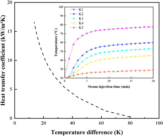
FIGURE 5. Variation in the heat transfer coefficient of steam on the condensation surface with temperature difference (the attached figure shows the change of temperature at thermocouple position with steam injection time).
The trend of the temperature curve of each thermocouple in Figure 5 shows that at the beginning of steam injection, the temperature of the condensation surface is the normal temperature 20°C, and the temperature difference between the steam and condensation surface is large. Therefore, the heat transfer between steam and condensation is obvious, and the temperature rises rapidly. However, with increasing surface temperature, the rate of temperature change gradually decreases, and the heat transfer process gradually tends to become stable. The temperature measured by each thermocouple is different and remains unchanged at a constant value. As the distance between the thermocouple and the condensation surface increases, the thermocouples are sequentially numbered K1, K2, K3, K4, and K5. Among them, K1 has the fastest temperature increase and the highest temperature value after stability. With increasing distance between the heat source and the thermocouple, the heating rate at the thermocouple gradually decreases, and the final stable temperature value decreases in turn and tends to a linear distribution. The relationship curve between the heat transfer coefficient and the change in temperature difference indicate that the heat transfer coefficient increases with decreasing temperature difference, and the growth rate becomes faster. In the initial stage of steam condensation, the greater the temperature difference is, the lower the actual condensation surface temperature, and the shorter the period from water droplets forming to falling off. With the development of condensation heat transfer, the temperature difference gradually decreases, the condensation surface temperature gradually approaches the temperature of injected steam, the condensation speed of steam on the surface becomes slower, the heat transfer coefficient is large, and more heat is transferred to the condensation surface.
CO2 was added to pure steam to form a gas-steam mixture without changing other conditions. After the condensation experiment, it was found that the condensation mode on the surface changed significantly. The experimental process is shown in Figure 6.
Figure 6 shows that no small water droplets appear on the condensation surface. A layer of water film is attached to the surface and thickens gradually with the introduction of a gas-steam mixture until the water film falls down and accumulates at the bottom layer due to the influence of gravity and falls off. The condensation is repeated throughout the process of the mixed steam entering the condensing chamber (Yuan et al., 2011). It is obvious that there is water film on the surface during steam condensation, and the thickness of the water film changes. However, the time that the surface is exposed to the steam is very short.
The most direct impact of this phenomenon is that the addition of CO2 inhibits the condensation heat transfer of steam. The heat transfer coefficient on the condensation surface of the gas-steam mixture is lower than that of pure steam with the same temperature difference. The mechanism explanation is shown in Figure 7. In the dropwise condensation mode with pure steam, the surface, except for the part covered by the liquid droplets, is exposed to the steam. Therefore, the heat exchange process is carried out between steam and liquid droplets and exposed surface. Since the surface area of the liquid droplet is much larger than the area it occupies and there is no liquid film thermal resistance on the exposed surface, dropwise condensation has a fast surface heat transfer rate. Even if a small amount of an NGC such as CO2 is added, the condensation mode on the condensation surface is film condensation. The heat transfer coefficient of the gas-steam mixture with CO2 is small due to the thermal resistance effect, on the one hand. According to the theory of convective heat transfer, in the process of film condensation heat transfer, there is liquid membrane resistance in the heat transfer resistance. As some of the CO2 molecules penetrate the liquid membrane layer, CO2 will accumulate continuously on the gas-liquid interface. There is also gas-phase membrane resistance, so the direct contact time between the steam and the surface is reduced. On the other hand, partial pressure of steam is less due to presence of CO2 in the mixture. The decrease in the saturation temperature of the steam causes the energy of the mixed steam to decrease. The combination of the two effects results in film condensation when the gas-steam mixture is added. The heat transfer coefficient of the film condensation mode under the same temperature difference is smaller than that of dropwise condensation (Chen et al., 2020a).
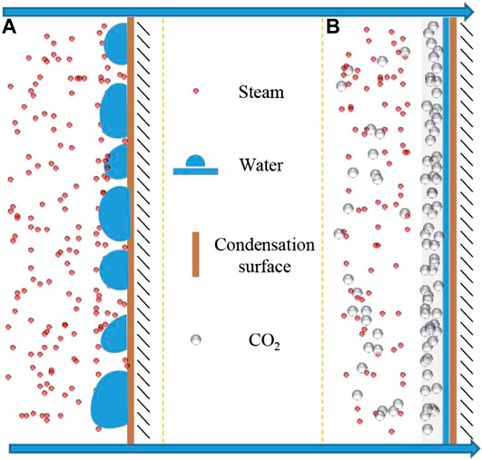
FIGURE 7. Schematic diagram of the steam condensation heat transfer mechanism with or without CO2. Adapted from (Wang et al., 2019).
The process of NCG-assisted steam injection is essentially a dynamic continuous process of condensation heat transfer. After the mixture is injected into the reservoir, the steam flows and transfers heat to the rocks and heavy oil. When the steam temperature is lower than the saturation temperature, it condenses on the rock surface and produces a phase transition (Wang et al., 2019).
From a microscopic view of the gas-steam mixture, both molecules move to the surface of the brass block, but the steam molecules are condensed into water, while the gas molecules are retained and gathered near the surface of the brass block. Therefore, it can be considered that in the schematic diagram of Figure 7, a non-condensable gas layer is formed between the steam molecules and the brass surface on a macroscopic level. Under pure steam injection conditions, the condensation heat flux is large. The mass transfer and phase transition of steam molecules are relatively fast. Under the action of gravity, the condensate droplets frequently fall off and wash the condensation surface. The gas-liquid interface is completely dynamic. With the increase of CO2 content, the falling off frequency of droplets is obviously slowed down, and the condensation morphology gradually transits to film condensation.
The boundary conditions are set. In the steady state of steam injection, the condensation surface temperature is 86.4°C according to the measured value of the experimental thermocouple. Therefore, the temperature of the simulated condensation surface is set at 86.4°C, the temperature of the cooling surface is 20°C, and the initial temperature of the condensate is 20°C. After reaching the steady state, the temperature distribution is shown in Figure 8B. Considering the connection between the measured position of the thermocouple and the comparison result of the corresponding simulated temperature value, the experimental value is shown in Figure 8A.
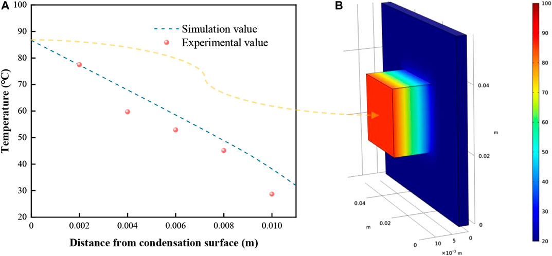
FIGURE 8. Comparison of simulation and experimental results of heat transfer in the condensate block. (A) is the change of temperature at different positions from the condensation surface, (B) is the three-dimensional distribution of the temperature field of the condensation block.
Figure 8 shows that from the condensation surface to the cooling surface, the temperature distribution in the condensate is decreasing. The inside of the condensing block is made of uniform brass, and the vertical surfaces are isothermal when heat conduction occurs. The experimental value measured by the thermocouple is less than or equal to the simulation value because the condensate is not completely insulated from the outside during the experiment. The heat loss from this part of the process is not considered in the simulation process, which is solved under ideal conditions. The trends in the simulation values and experimental values are basically the same, so more factors are considered in the follow-up research.
Combined with the different phenomena on the condensation surface obtained from the experiment, dropwise condensation appears with pure steam injection, and film condensation appears with gas-steam mixture injection with CO2. Considering the difference in thermal resistance caused by the two condensation modes, ignoring the change of steam partial pressure and assuming that the condensation surface is in a dynamic stable state, the models are established as shown in Figures 9A,C. In Figure 9A, a total of 16 water droplets are uniformly distributed on the condensation surface, each of which has a diameter of 5 mm. In Figure 9C, a CO2 gas film with a thickness of 0.5 mm is distributed, and a water film with a thickness of 2 mm is distributed between the gas film and the condensation surface. The condensation surface is set to be in thermal contact with the steam, and the steam temperature is 100°C. After reaching the steady state, the temperature distributions of the condensation block are shown in Figures 9B,D.
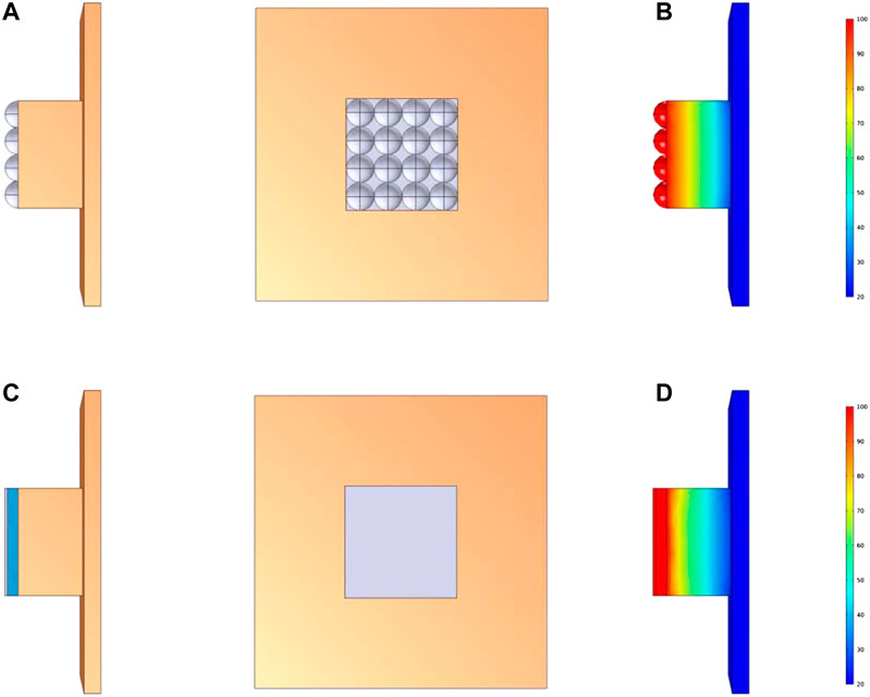
FIGURE 9. Comparison of simulation modeling between dropwise condensation and film condensation. (A) and (C) are the modeling diagrams of dropwise condensation and film condensation respectively, (B) and (D) are the steady-state temperature fields of dropwise condensation and film condensation, respectively.
Figure 9 shows that the temperature gradient in the dropwise condensation mode is larger than that in the film condensation mode. The temperature change curves along the thermocouple connection under the two condensation modes are compared, as shown in Figure 10. The presence of gas in the steam chamber, reservoir rocks and heavy oil may reduce the heat transfer efficiency, which affects the expansion of the steam cavity (Pang et al., 2017).
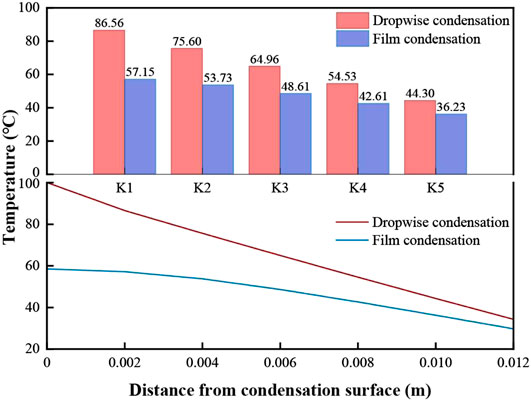
FIGURE 10. Comparison of the temperature at each thermocouple in dropwise condensation and film condensation.
Figure 10 shows that the temperature at the condensation surface in the dropwise condensation mode is 100°C, and the temperature at the condensation surface in the film condensation mode is less than 60°C. The reason for this difference is that at the measured position, the surface in the dropwise condensation mode directly contacts the steam for heat exchange. With the gas film and liquid film barriers, the temperature transferred to the surface in the film condensation mode is greatly reduced. From thermocouple K1 to K5, the temperature in the dropwise condensation mode is greater than the temperature in the film condensation mode at each position, but as the distance between the thermocouple and the condensation surface increases, the temperature difference between the two modes decreases.
It should be noted that although the film condensation has a good inhibition effect on the steam heat transfer because the thermal resistance layer is a pre-set immovable unit, the temperature at the location of the thermocouple cannot represent the whole condensation heat transfer process, which needs further comprehensive analysis. The area of the condensation surface is calculated to obtain the average temperature, and the volume of the condensation block is calculated to obtain the average temperature. The comparison of the average temperature in the two modes is shown in Figure 11.
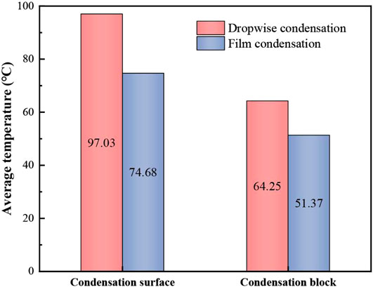
FIGURE 11. Comparison of the average temperature between dropwise condensation and film condensation.
Figure 11 shows that in the dropwise condensation and film condensation modes, the average temperature difference on the condensation surface is smaller than the average temperature difference in the condensation block. This is because in the dropwise condensation mode, there is an exposed area on the condensation surface that directly contacts the steam. The thermal conductivity of metal is greater than that of the gas film and the liquid film, and the distance between gas molecules is relatively large. The gas depends on the irregular thermal movement of molecules and the collision between molecules, which causes energy transfer within the gas, thus forming a macroscopic heat transfer. The average temperature of the condensate is the most representative of heat transfer. The average temperature of the condensate in the film condensation mode is 12.88°C lower than that in the dropwise condensation mode, and the decrease range is 20.05%, which is less than the 23.03% on the condensation surface. This shows that the addition of CO2 indirectly inhibits the heat transfer of steam by changing the condensation mode (Xu et al., 2016).
In this section, the change in condensation mode and flow regime is not considered; only the influence of the steam flow rate and CO2 content change on the condensation surface temperature is considered.
The free interface between gas and liquid can be obtained by surface tracking. The gas volume fraction
With the steam temperature set at 100°C, the phase transition temperature between the water phase and steam phase is 100°C, and the latent heat from the water phase to the steam phase is 2,257.2 kJ/kg. By changing the injection rate of the steam, changes in the condensation surface temperature and phase change field of the condensation chamber are studied, as shown in Figure 12.
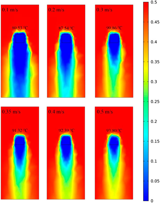
FIGURE 12. The effect of the change in the steam flow rate on the phase change field (the steam flow rate and the condensation surface temperature are given in the figure).
Figure 12 shows that the phase transition of steam occurs after the steam is injected into the condensation chamber, where gas and liquid phases coexist. This leads to a decrease in steam quality, and the condensation phenomenon is concentrated on the condensation surface and its lower part. The results of this study are similar to those found by Wu and Vierow (Wu and Vierow, 2006) that the condensation heat transfer coefficient at the top is greater than that at the bottom. As the steam flow rate increases, the steam in the condensing chamber can still maintain a high degree of quality. The temperature of the condensing surface gradually increases, and the increase rate becomes slower, eventually approaching 100°C.
During the process of steam injection, there are three heat transfer modes, steam condensation at the interface, significant convection heat transfer from steam to the interface, and conduction through liquid condensate (Dehbi, 2015). Under the same pressure condition, the heat transfer rate and heat transfer coefficient increase with the increase of steam flow rate at the inlet. A higher inlet flow leads to a larger interfacial shear force, which reduces the thickness of the liquid phase on the condensing surface and accelerates the shedding speed of the liquid phase, both are reasons for reducing the heat transfer resistance of the liquid phase. At the same time, the high steam flow rate brings a large heat flux, which also promotes heat transfer. It is worth noting that the velocity change caused by the increase in flow affects the flow regime, which also has an important impact on the heat transfer process. This is the focus of our next research.
To explore the influence of carbon dioxide content on the inhibition of steam heat transfer, the constant mixed steam flow rate was 0.35 m/s, the CO2 contents were set as 0% (pure steam), 20%, 40%, 60%, 80%, and 100% (pure CO2), and the initial CO2 temperature was 20°C. After mixing with steam, the partial pressure of steam and the temperature of the gas-steam mixture are affected. In this process, changes in other physical parameters are ignored. The temperature of the gas-steam mixture under different CO2 contents and the temperature of the condensation surface after reaching the steady state are compared, as shown in Figure 13.
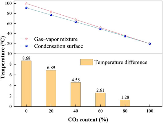
FIGURE 13. The gas-steam mixture temperature with different CO2 contents and the temperature of the condensation surface after reaching a steady state.
As shown in Figure 13, with an increase in CO2 content, the temperature of the gas-steam mixture decreases linearly, and the temperature difference between the gas-steam mixture and the condensation surface gradually decreases after reaching the steady state. This indicates that heat transfer requires a temperature difference as the spontaneous power, and the addition of CO2 reduce the partial pressure of the steam. The condensation heat transfer coefficient decreases with increasing CO2 mass fraction and decreases with decreasing total system pressure.
The partial pressure of steam decreases with the increase of CO2 content. The accumulation of CO2 reduces the interface saturation temperature (corresponding to the interface steam partial pressure) at the gas-liquid interface, which leads to a decrease in the temperature difference between the steam and the condensation surface, that is, the driving force for condensation decreases, and the condensation effect becomes worse. In the reservoir developed by steam injection, whether the heat of steam acts on the reservoir is the key to determine the development effect. When steam and CO2 are injected into the reservoir together, due to the low heat transfer coefficient of the gas-steam mixture in the rock formations along the way, the steam can maintain the gas phase through a longer flow distance, which increases the sweep range. At the same time, when acting on the cold oil zone, the residual heat of steam is higher, which can effectively heat the crude oil to reduce viscosity and improve its fluidity. Moreover, due to the slowing down of condensation process, the water content in the production process is relatively low, which is one of the key reasons for enhanced oil recovery.
NCG-assisted steam injection has an impact on the expansion of the steam chamber, which in turn affects the development of heavy oil reservoirs. The following four major conclusions were drawn from the results of this study:
(1) When pure steam is injected, the heat transfer coefficient increases with the decrease of temperature difference, and is affected by the steam flow rate. After the addition of CO2, the condensation mode changes from dropwise condensation to film condensation, which inhibits the condensation heat transfer of the steam.
(2) Film condensation has a high thermal resistance when composed of a gas film and a liquid film. Compared with dropwise condensation, after the heat is transferred to the condensation surface, the temperature decreases by 23.03%, and the average temperature of the entire condensation block decreases by 23.03%.
(3) A phase transition occurs after the steam is injected into the condensation chamber, and the condensation is concentrated near the brass block surface and its lower part. As the steam flow rate increases, the steam in the condensation chamber can still maintain a high degree of quality, the temperature of the condensation surface gradually increases, and the increase rate becomes slower.
(4) With the increase of CO2 content, the temperature of the gas-steam mixture decreases linearly. The high CO2 content brings a small heat flux, which also inhibits heat transfer process. The co-injection of steam and CO2 is beneficial to improve the development effect of steam in the reservoir.
The raw data supporting the conclusions of this article will be made available by the authors, without undue reservation.
All authors listed have made a substantial, direct and intellectual contribution to the work, and approved if for publication.
This project was financially supported by the National Natural Science Foundation of China (No. 51774306 and No. 51974346), National Key Scientific and Technological Project for the Oil & Gas Field and Coalbed Methane of China (2016ZX05031002-004-002), and the Youth Innovation of University in Shandong Province under (No. 2019KJH002). We are grateful to the Shandong Engineering Research Center for Foam Application in Oil and Gas Field Development and UPC-COSL Joint Laboratory on Heavy Oil Recovery for their assistance with the experimental research.
Author HB was employed by the company China National Aviation Fuel Southwest Storage & Transportation Co., Ltd.
The remaining authors declare that the research was conducted in the absence of any commercial or financial relationships that could be construed as a potential conflict of interest.
Ali, H., Sheng Wang, H., Briggs, A., and Rose, J. W. (2013). Effects of vapor velocity and pressure on marangoni condensation of steam-ethanol mixtures on a horizontal tube. J. Heat Trans. 135 (3), 10. doi:10.1115/1.4007893
Baik, W., and Yun, R. (2019). In-tube condensation heat transfer characteristics of CO2 with N2 at near critical pressure. Int. J. Heat Mass Tran. 144, 118628. doi:10.1016/j.ijheatmasstransfer.2019.118628
Briggs, A., and Sabaratnam, S. (2003). Condensation of steam in the presence of air on a single tube and a tube bank. Int. J. Energy Res. 27 (4), 301–314. doi:10.1002/er.876
Cabeza, L. F., de Gracia, A., Fernández, A. I., and Farid, M. M. (2017). Supercritical CO2 as heat transfer fluid: a review. Appl. Therm. Eng. 125, 799–810. doi:10.1016/j.applthermaleng.2017.07.049
Chen, H., Wang, Z., Wang, K., Li, Z., and Li, S. (2020a). Investigation of EOR mechanism for flue gas assisted SAGD. J. Petrol. Sci. Eng. 193, 107420. doi:10.1016/j.petrol.2020.107420
Chen, L., Huang, M., Li, Z., Liu, D., and Li, B. (2020b). Experimental study on the characteristics of foam flow in fractures. J. Petrol. Sci. Eng. 185, 106663. doi:10.1016/j.petrol.2019.106663
Dehbi, A. (2015). A generalized correlation for steam condensation rates in the presence of air under turbulent free convection. Int. J. Heat Mass Tran. 86, 1–15. doi:10.1016/j.ijheatmasstransfer.2015.02.034
Erpeng, G., Youwei, J., Yongrong, G., Hongzhuang, W., and Pengbo, Y. (2015). “Discussion on the first N-SAGD pilot test in China,” in SPE Asia Pacific Enhanced Oil Recovery Conference. Kuala Lumpur, Malaysia. 11–13 August, 2015 (Society of Petroleum Engineers). doi:10.2118/174655-ms
Ge, M., Zhao, J., and Wang, S. (2013). Experimental investigation of steam condensation with high concentration CO2 on a horizontal tube. Appl. Therm. Eng. 61 (2), 334–343. doi:10.1016/j.applthermaleng.2013.08.013
Law, D. H.-S. (2004). “Disposal of carbon dioxide, a greenhouse gas, for pressure maintenance in a steam-based thermal process for recovery of heavy oil and bitumen,” in SPE International Thermal Operations and Heavy Oil Symposium and Western Regional Meeting. Bakersfield, CA. 16–18 March 2004 (Society of Petroleum Engineers). doi:10.2118/86958-ms
Lawal, K. A. (2014). Economics of steam-assisted gravity drainage for the Nigerian Bitumen deposit. J. Petrol. Sci. Eng. 116, 28–35. doi:10.1016/j.petrol.2014.02.013
Li, S., Li, Z., and Sun, X. (2017). Effect of flue gas and n -hexane on heavy oil properties in steam flooding process. Fuel 187, 84–93. doi:10.1016/j.fuel.2016.09.050
Li, S., Wang, Q., Zhang, K., and Li, Z. (2020). Monitoring of CO2 and CO2 oil-based foam flooding processes in fractured low-permeability cores using nuclear magnetic resonance (NMR). Fuel 263, 116648. doi:10.1016/j.fuel.2019.116648
Li, Z., Xu, Z., Li, B., Wang, F., Zhang, Z., Yang, H., et al. (2019). Advances in research and application of foam flooding technology. J. of China Univ. of Pet. 43(5), 118–127. doi:10.3969/j.issn.1673-5005.2019.05.013
Lu, J., Cao, H., and Li, J. (2019a). Experimental study of condensation heat transfer of steam in the presence of non-condensable gas CO2 on a horizontal tube at sub-atmospheric pressure. Exp. Therm. Fluid Sci. 105, 278–288. doi:10.1016/j.expthermflusci.2019.04.004
Lu, J., Cao, H., and Li, J. (2019b). Theoretical modeling of vapor condensation in the presence of noncondensable gas on a horizontal tube. J. Heat Trans-T ASME. 141 (12), 9. doi:10.1115/1.4044703
Oh, S., and Revankar, S. T. (2006). Experimental and theoretical investigation of film condensation with noncondensable gas. Int. J. Heat Mass Tran. 49 (15), 2523–2534. doi:10.1016/j.ijheatmasstransfer.2006.01.021
Othmer, D. F. (1929). The condensation of steam. Ind. Eng. Chem. 21 (6), 576–583. doi:10.1021/ie50234a018
Pang, Z., Wu, Z., and Zhao, M. (2017). A novel method to calculate consumption of non-condensate gas during steam assistant gravity drainage in heavy oil reservoirs. Energy 130, 76–85. doi:10.1016/j.energy.2017.04.078
Ren, B., Zhang, L., Cao, J., Xu, H., and Tao, Z. (2015). Experimental and theoretical investigation on condensation inside a horizontal tube with noncondensable gas. Int. J. Heat Mass Tran. 82, 588–603. doi:10.1016/j.ijheatmasstransfer.2014.11.041
Su, J., Sun, Z., Ding, M., and Fan, G. (2014). Analysis of experiments for the effect of noncondensable gases on steam condensation over a vertical tube external surface under low wall subcooling. Nucl. Eng. Des. 278, 644–650. doi:10.1016/j.nucengdes.2014.07.022
Wang, Z., Li, Z., Sarma, H. K., Xu, Y., Wu, P., Yang, J., et al. (2019). A visualization experimental study on gas penetration through interlayer to improve SAGD performance. J. Petrol. Sci. Eng. 177, 959–970. doi:10.1016/j.petrol.2019.03.001
Wu, T., and Vierow, K. (2006). Local heat transfer measurements of steam/air mixtures in horizontal condenser tubes. Int. J. Heat Mass Tran. 49 (15), 2491–2501. doi:10.1016/j.ijheatmasstransfer.2006.01.025
Wu, Z., Liu, H., and Wang, X. (2018). 3D experimental investigation on enhanced oil recovery by flue gas coupled with steam in thick oil reservoirs. Energy Fuels. 32(1), 279–286. doi:10.1021/acs.energyfuels.7b03081
Xu, H., Sun, Z., Gu, H., and Li, H. (2016). Forced convection condensation in the presence of noncondensable gas in a horizontal tube; experimental and theoretical study. Prog. Nucl. Energy. 88, 340–351. doi:10.1016/j.pnucene.2016.01.013
Xu, Z., Li, S., Li, B., Chen, D., Liu, Z., and Li, Z. (2020b). A review of development methods and EOR technologies for carbonate reservoirs. Petrol. Sci. 17 (4), 990–1013. doi:10.1007/s12182-020-00467-5
Xu, Z., Li, B., Zhao, H., He, L., Liu, Z., Chen, D., et al. (2020a). Investigation of the effect of nanoparticle-stabilized foam on EOR: nitrogen foam and Methane foam. ACS Omega. 5 (30), 19092–19103. doi:10.1021/acsomega.0c02434
Xu, Z., Li, Z., Jing, A., Meng, F., Dang, F., and Lu, T. (2019). Synthesis of magnetic graphene oxide (MGO) and auxiliary microwaves to enhance oil recovery. Energy Fuels. 33 (10), 9585–9595. doi:10.1021/acs.energyfuels.9b01841
Yee, C. T., and Stroich, A. (2004). Flue gas injection into a mature SAGD steam chamber at the dover project (formerly UTF). J. Can. Petrol. Technol. 43 (01), 8. doi:10.2118/04-01-06
Yuan, J., Chen, J., Pierce, G., Wiwchar, B., Golbeck, H., Wang, X., et al. (2011). Noncondensable gas distribution in SAGD chambers. J. Can. Petrol. Technol. 50 (03), 11–20. doi:10.2118/137269-PA
Zhang, K., Jia, N., Li, S., and Liu, L. (2018). Millimeter to nanometer-scale tight oil-CO2 solubility parameter and minimum miscibility pressure calculations. Fuel 220, 645–653. doi:10.1016/j.fuel.2018.02.032
Keywords: steam injection, simulation method, experimental method, condensation mode, CO2 content, heat transfer inhibition
Citation: Xu Z, Li Z, Li B, Li S, Lu T, Wu M and Bai H (2020) Investigation of the Heat Transfer Mechanism of CO2-Assisted Steam Injection via Experimental and Simulation Evaluation. Front. Energy Res. 8:592142. doi: 10.3389/fenrg.2020.592142
Received: 06 August 2020; Accepted: 29 September 2020;
Published: 30 October 2020.
Edited by:
Simona Liguori, Clarkson University, United StatesReviewed by:
Ahmet Arısoy, Istanbul Technical University, TurkeyCopyright © 2020 Xu, Li, Li, Li, Lu, Wu and Bai. This is an open-access article distributed under the terms of the Creative Commons Attribution License (CC BY). The use, distribution or reproduction in other forums is permitted, provided the original author(s) and the copyright owner(s) are credited and that the original publication in this journal is cited, in accordance with accepted academic practice. No use, distribution or reproduction is permitted which does not comply with these terms.
*Correspondence: Zhaomin Li, bGl6aG1AdXBjLmVkdS5jbg==
Disclaimer: All claims expressed in this article are solely those of the authors and do not necessarily represent those of their affiliated organizations, or those of the publisher, the editors and the reviewers. Any product that may be evaluated in this article or claim that may be made by its manufacturer is not guaranteed or endorsed by the publisher.
Research integrity at Frontiers

Learn more about the work of our research integrity team to safeguard the quality of each article we publish.