 Sylvain Rodat
 Stéphane Abanades
95% of researchers rate our articles as excellent or good
Learn more about the work of our research integrity team to safeguard the quality of each article we publish.
Find out more
ORIGINAL RESEARCH article
Front. Energy Res. , 28 August 2020
Sec. Advanced Clean Fuel Technologies
Volume 8 - 2020 | https://doi.org/10.3389/fenrg.2020.00206
This article is part of the Research Topic Technology Advances in the Utilization of Fossil Natural Gas as a Strategy in Transition to a Sustainable Energy System View all 7 articles
Solar natural gas thermal dissociation, producing both hydrogen and solid carbon, appears as a promising way for progressive decarbonization of the world energy mix. Three main challenges remain to be tackled: carbon deposition issue, continuous round the clock operation of the solar reactor with an intermittent energy resource, and technology scale-up. The present work proposes a new windowless scalable solar reactor enabling volumetric gas-phase (i.e., not at the walls) methane cracking with possible hybridization. CFD simulations demonstrate the advantage of the new concept as compared to conventional tubular reactors. The proposed system uses a hot inert gas to generate a high temperature fluid zone similar to a combustion flame where the methane decomposition occurs. Based on the numerical model developed, a sensitivity study is carried out in order to optimize the reactor design enabling both high methane conversion and low carbon deposition. For methane flow-rates of 4.6 × 10⁻⁶ kg.s–1 and 2.3 × 10⁻⁶ kg.s–1 (argon flow-rate of 9.3 × 10⁻⁵ kg.s–1), methane conversion reached 46 and 73% for maximum fluid zone temperatures of 1676 and 1750 K, respectively. Furthermore, electric hybridization is investigated in order to highlight the potential for day and night continuous operation. Indeed, since an inert carrier gas is used as heat transfer medium, it can be heated by different energy sources to maintain the thermal power input during low irradiation periods. Thus, the solar flame concept that we previously patented proves to be of interest for practical implementation to introduce solar heat into high temperature processes.
In the way toward the reduction of CO2 emissions associated with the utilization of fossil fuels, hydrogen appears as a valuable energy vector that can be used in various industrial or transportation sectors to displace fossil energy sources. The challenge for chemical engineering is to produce it in a sustainable way, preferably using renewable energies, at an acceptable cost (Arastoopour, 2019). A smooth energy transition could possibly rely on methane cracking, as natural gas reserves are still huge (Weger et al., 2017). Methane dissociation can be carried out in 3 ways: direct thermal cracking, catalytic cracking or electrochemical processes (plasma cracking) (Abánades et al., 2012). Concentrated solar energy has been widely investigated to provide renewable high temperature heat for the direct or catalytic process (Ozalp et al., 2009). The solar process enables to use a widely distributed fossil energy (methane) to produce a decarbonized H2 form without CO2 emissions given that carbon is recovered in the solid form. Moreover, a recent work revealed that the process could drastically improve solar-to-electricity efficiency using hydrogen and carbon fuel cells (Ozalp et al., 2018). The direct methane dissociation can be written as:
The reaction extent can be characterized by the methane conversion defined as the ratio of converted methane to the initial methane feed.
With F0,CH4 the inlet methane flow-rate and FCH4 the outlet methane flow-rate (mol.s–1).
Past works on methane dissociation have considered different solar reactors with two main concepts: direct (Kogan et al., 2007; Abanades and Flamant, 2008; Maag et al., 2009) or indirect heating (Rodat et al., 2010, 2011; Abanades et al., 2015). In the former, the carbon seeded reactive gas is directly irradiated by concentrated solar energy through a transparent window, leading to very high heat transfer rates at particles surface along with catalytic effects. The main drawback is the possible carbon deposition issue on the window. The latter uses an opaque separation wall transferring solar heat by conduction to the reacting medium. This option lowers the thermal efficiency, but does not require introducing carbon particles and can eliminate the use of a window. However, carbon deposition on the tube wall has been reported (Abánades et al., 2011). This is because in the indirect heating configuration, the tube wall is the hottest zone where the reaction is favored. Thus, methane dissociates mainly on the hot surface, whereas the conventional furnace black process for hydrocarbons dissociation intrinsically involves a volumetric reaction in the combustion flame. In order to avoid the carbon deposition issue, Wyss et al. (2007) proposed the solar fluid-wall configuration with two concentric tubes. The outermost tube received solar irradiation. In the annular zone, a flow of hydrogen was injected while in the innermost tube, methane was injected. As the innermost tube was porous, hot hydrogen could pass through it and carry heat for the methane dissociation while avoiding carbon deposition on the wall. Given that the tube was made of graphite, the concept still required a window to avoid carbon oxidation. Other non-solar options were investigated to study possible effect of catalysts, either carbon-based or metallic (Abbas and Wan Daud, 2010). Plasma reactors for hydrogen and carbon black production process were also explored (da Costa Labanca, 2020). A commercial plant is currently being deployed by Monolith Material company in Nebraska. Molten metal reactors were considered as well (Geißler et al., 2016). Methane was bubbling into a bath of molten media, so that it could dissociate into gaseous hydrogen and solid carbon floating at the surface. In this configuration, even if methane dissociation occurs in the liquid volume, interaction between carbon and metal may lead to more graphitic carbon than what is expected in a gas. The recovery of carbon remains also a challenge.
Besides the carbon deposition issue, the second obstacle that is more general and applicable to almost all previous solar thermochemical reactors is that operation is only diurnal leading to transient operation and shut down at night. This leads to low thermal efficiency and difficult control of process parameters, especially the temperature. For that purpose, hybridization appears as an interesting option in order to maintain operation round the clock. Electric or fossil fuel hybridization of solar reactors was recently proposed (Chinnici et al., 2018; Rowe et al., 2018). Eventually, most of the solar reactors make use of a window that can hardly be applied in scaled-up reactors.
To tackle all these issues, the solar flame concept has been patented by the authors (Rodat et al., 2017) and the present work aims at providing first insights into the possible benefits of such configuration. A new hybrid windowless solar tubular reactor for continuous volumetric natural gas dissociation is presented and examined thanks to Computational Fluid Dynamics (CFD) simulations. First, the solar reactor concept (design and geometry) and model are depicted, and then a parametric study is carried out in order to size a future prototype (tube configuration, flow rates, preheating) and to evaluate its thermochemical performance, especially in terms of methane conversion. The innovative dual tube configuration is compared to conventional single tube designs.
The reactor concept is depicted in Figure 1 including a schematic 3D view of the solar reactor without the insulation layer (left), along with the corresponding axisymmetric geometry used for the simulation (right). It features a tubular design and it is composed of 2 concentric alumina tubes. The innermost tube is 6 mm O.D. and 3 mm I.D. for a total length of 270 mm while the outermost tube is 25 mm O.D. and 20 mm I.D. for a total length of 500 mm. The tube is inserted in an alumina cavity receiver of 40 mm height and 45 mm inner diameter including a 16 mm diameter aperture. This unwindowed opening lets concentrated solar energy enter into the black body type receiver. The reaction occurs inside the tubes and the windowless solar reactor is based on indirect heating via the intermediate tube wall. On top of the solar cavity, the tube can be heated by an electric heating element for possible hybridization of the reactor. The reactor is surrounded by a 70.5 mm insulating material (maximum thickness) with a conical extrusion around the cavity aperture to let concentrated solar energy enter. Gas inlets are located at the top, and outlet is at the bottom. Inlets and outlet sealings are water-cooled. For the simulation, a simplified axisymmetric geometry is proposed considering the tubular design of the reactor. An 85 mm heating zone is defined on the outermost tube starting 15 mm above the cavity top. This zone stands for the resistive heater. The modeled cavity has a 1 mm high aperture leading to a total cylindrical surface of 2.14 × 10⁻⁴ m2 around the reactor axis corresponding to the real total surface of the circular aperture of the 3D mockup (16 mm diameter). Due to the axisymmetry, the conical extrusion in the insulation layer is transformed into a V-shaped extrusion around the reactor axis. The gravity is in the direction of the axis, toward the outlet.
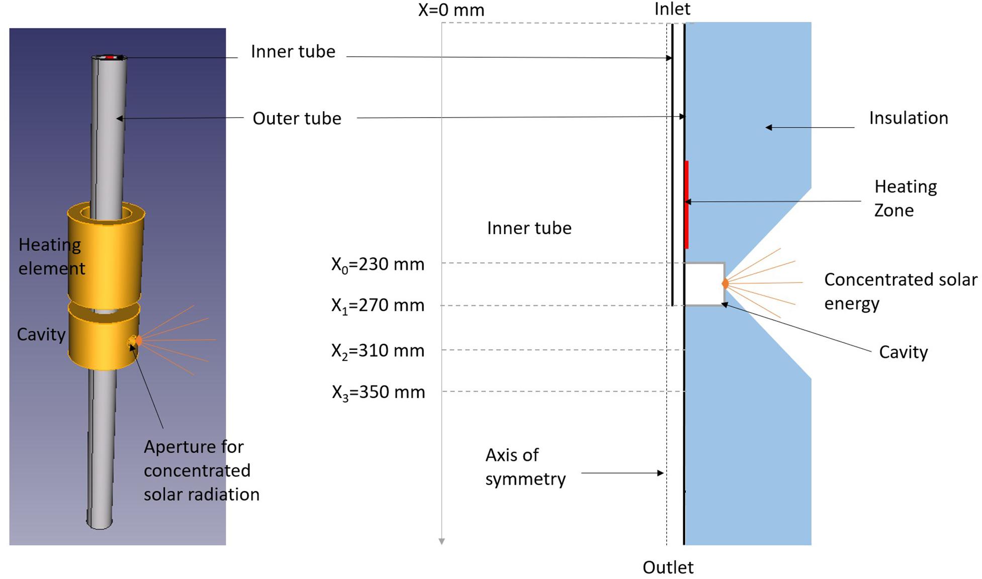
Figure 1. 3D schematic view of the reactor without insulation and geometry used for axisymmetric modeling.
The aim of this new solar tubular reactor is to investigate the patented technology of the solar flame proposed by Rodat et al. (2017). It consists in using a high temperature gas heated by solar energy to replace the combustion flame for example in the furnace black process. The advantage is that the gaseous heat transfer fluid can be heated by solar energy leading to a “sustainable flame” as no fossil fuel combustion is required. A close concept was previously proposed by Shpilrain et al. (1999) who investigated the pyrolysis technology “in the free volume” in High Temperature Regenerative Gas Heaters in order to avoid pyrocarbon formation on reaction surfaces. However, fossil fuel combustion was considered for thermal power input. An inert argon flame was simulated in a carbon black furnace for sour natural gas decomposition by Javadi et al. (2010). Thermal decomposition of methane in the products of premixed flames was also recently reported by Afroughi et al. (2019). If the reported H2 yield of about 80% was encouraging, the carbon yield was very low. According to the authors, it was due to the gasification reaction. However, acetylene concentration was not measured and the presence of C2H2 could also explain the low carbon yield. Thus, it seems pertinent to study the effect of the direct methane cracking into the solar flame, in order to control the flame composition (containing inert gas) along with the heating source (concentrated solar power). The proposed configuration enables to preheat argon gas in the annular space of the tubular reactor before injecting methane into this hot gas flow via the central tube. Numerical simulations are required in order to evaluate the most suitable configuration of the reactor (mainly: gas flow-rates and innermost tube length) while enabling reasonable methane conversion with limited carbon deposit.
The whole simulation was developed on ANSYS workbench (v19.2). The geometry was designed with SpaceClaim, while Meshing software was used for generating the mesh and Fluent as the CFD tool (see Supplementary Material 1 for the mesh independence study and convergence conditions). Steady-state, pressure based, axisymmetric Fluent model was used. Standard momentum, energy and mass conservation equations and dedicated models included in the software were used without modification (ANSYS Inc., 2018). The hydrodynamic model was laminar. Whatever the configuration, the Re number is indeed lower than 350, this value being identified as the critical Reynolds number (transition between laminar to turbulent flow) for confined co-axial jets (Gore and Crowe, 1988). Energy conservation equation was solved. The Discrete Ordinates model was used to take into account radiative heat transfer assuming a gray model (Theta and Phi divisions set to 4 and Theta and Phi pixels to 3). A semi-transparent wall enabled to simulate direct solar radiation along the reactor radial direction. The radiative flux was assumed diffuse and homogeneous at the cavity entrance, which reasonably allows representing the real solar power absorbed by the cavity receiver although not accounting for the real flux direction and distribution. The mass transfer model included species transport coupled with volumetric reaction. The kinetic rate of methane decomposition reaction was represented by a first order finite rate reaction [reaction (1)], according to the Arrhenius law with a pre-exponential factor of 2 × 10¹⁰ s–1 and an activation energy of 281 kJ/mol (Rodat et al., 2009).
Two solid materials were defined: alumina tube and insulation that represent the solid zones of the reactor, along with four mixture species inside the tube (fluid zone): argon, methane, carbon-solid (dedicated specie in Fluent to consider solid carbon formation as a mixture specie in the gas phase to avoid multiphase flow simulation) and hydrogen. The main physical properties are given in Table 1 for solid zones (thermal conductivity is calculated for a specific temperature in K according to a piecewise linear model) and in Table 2 for species of the fluid zone inside the tube (physical properties are function of temperature T in K). Gas density is estimated according to the incompressible ideal gas law. Mass diffusivity of the mixture is set to 2.88 × 10⁻⁵ m2/s. Regarding the boundary conditions, entrance and exit of the tubes are set to a temperature of 300 K to consider water cooling of seals. For all other external surfaces, the thermal boundary condition is natural convection (with heat transfer coefficient set to 10 W/m2/K).
Table 1. Main properties of solids.
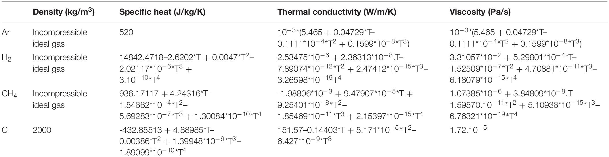
Table 2. Main properties of fluids.
Three configurations have been compared in order to demonstrate the interest in the use of a central methane injection as compared to the single tube design. First, a single tube was simulated. Then, two central methane injections were evaluated either with an innermost tube of 230 mm (methane injection is just at the beginning of the solar cavity) or 270 mm (methane injection is just after the solar cavity). When a central injection is used, only methane is introduced in the innermost tube while only argon flows in the outermost tube. In all cases, the mass flow-rate of argon is 2.3 × 10⁻⁴ kg.s–1 (7.81 NL/min – NL means Normal Liter at 101325 Pa and 273.15 K) and the mass flow-rate of methane is 9.2 × 10⁻⁶ kg.s–1 (0.77 NL/min). It corresponds to an argon inlet velocity of 0.5 m/s and a methane inlet velocity of 2 m/s. A solar flux density of 4 MW/m2 is set at the cavity aperture (semi-transparent wall), corresponding to a total incident power of 854 W. The heating element is off.
In order to be able to compare the new design with a conventional tubular configuration, a simulation with a single tube (25 mm O.D. and 20 mm I.D.) was carried out. Figure 2 provides the temperature contour of the reactor. It can be seen that the maximum temperature in the solar cavity is quite homogeneous with a maximum value of about 1900 K. A maximum gas temperature of 1020 K on the tube axis and a maximum wall temperature of 1870 K are obtained. The final methane conversion is 22%. As observed in Figure 3A, methane mainly dissociates near the tube wall where the temperature is maximum. As a consequence, the carbon formation (Figure 3B) tends to occur directly on the hot wall surface possibly leading to carbon deposition. In order to overcome these limitations, a central injection is proposed and investigated in the following.
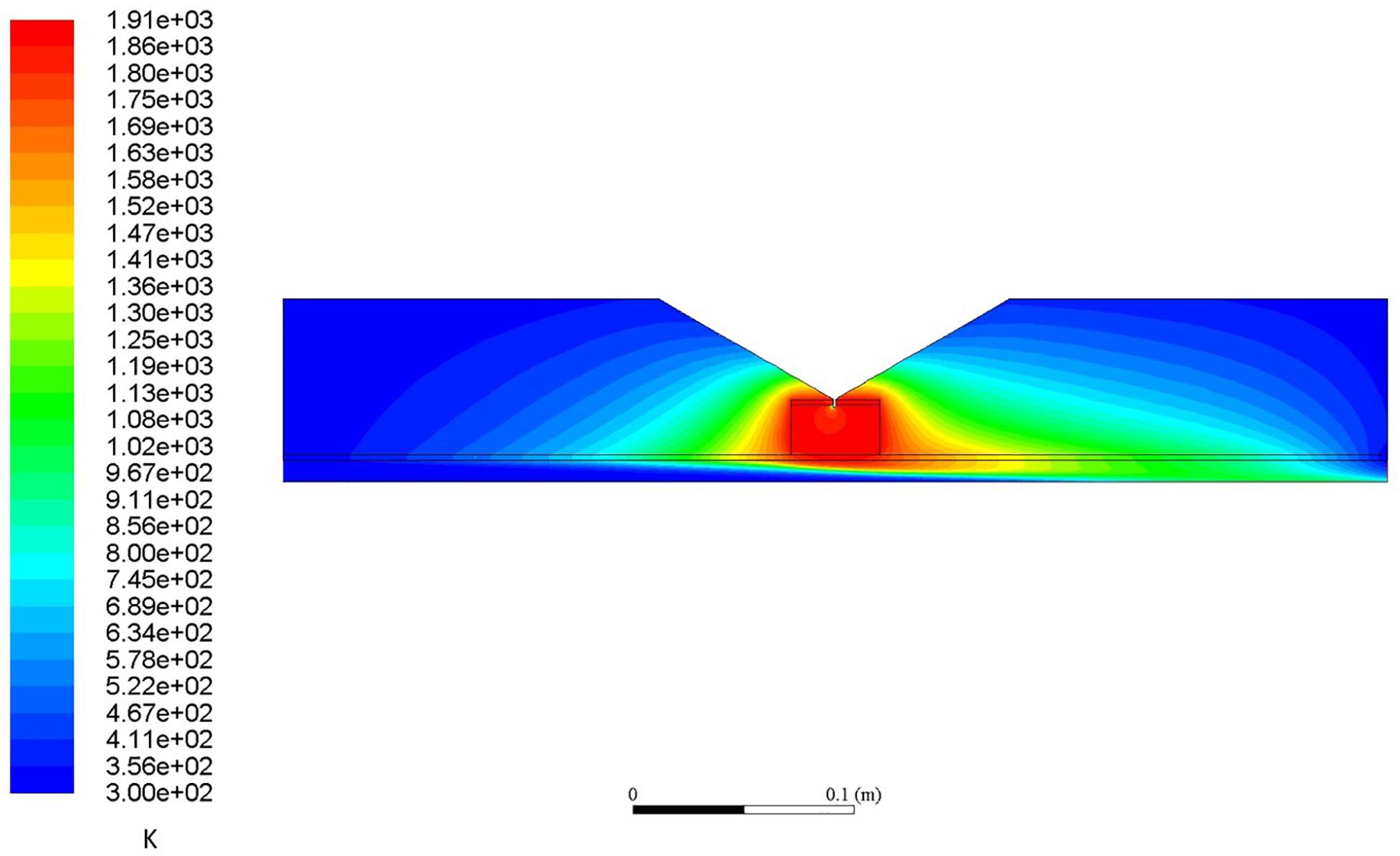
Figure 2. Temperature contour for the single tube configuration (K).
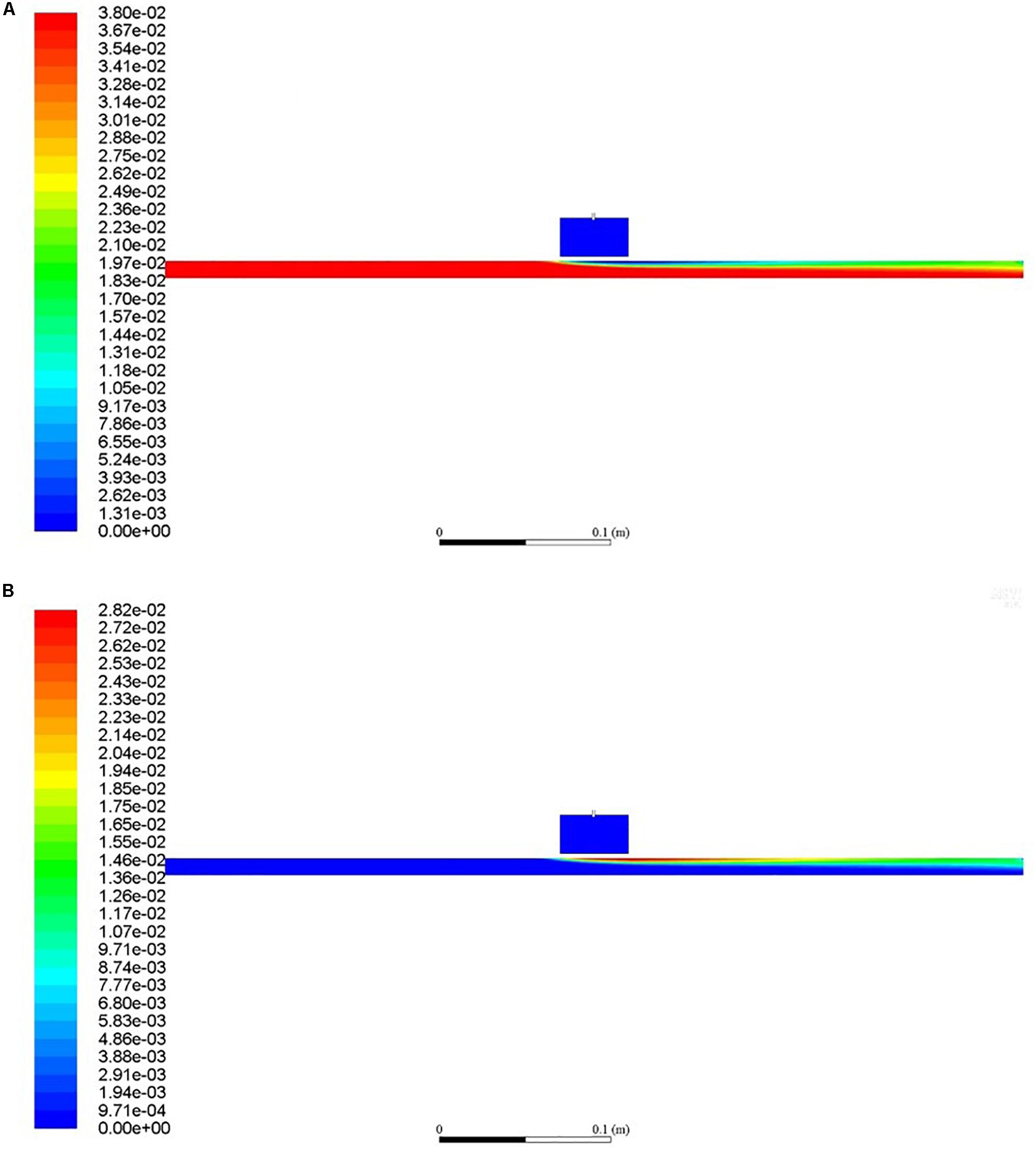
Figure 3. CH4 (A) and C (B) mass fraction for the single tube configuration.
In order to evaluate the impact of a central tube injection of methane, two dual tube configurations were simulated for an innermost tube length of 270 and 230 mm. Both configurations are compared with the single tube configuration. In Figure 4, the wall and on-axis temperatures are reported along the tube length for the single tube configuration and the two dual tube configurations. The zone between X = 0.23 m and X = 0.27 m corresponds to the solar cavity. It can be noted that the three configurations lead to tube wall temperatures exceeding 1800 K in the vicinity of the solar cavity. The main differences are obviously observed on the symmetry axis. For the single tube configuration, the temperature on the axis is limited to a maximum of 1020 K at 5 cm before the exit while the maximum temperature reaches 1300 and 1750 K toward the exit of the innermost tube for the dual tube configurations 230 and 270 mm, respectively. The presence of an additional inner tube improves heat transfers thanks to additional heat transfer surface. It can be seen that for the dual tube configurations, the temperature on the axis exceeds the outermost tube wall temperature at X = 0.36 m and X = 0.3 m for the respective tube lengths of 230 and 270 mm. For the single tube configuration, the wall temperature exceeds the on-axis temperature only at X = 0.42 m. This implies that a central injection enables to introduce methane in a hot gas zone on the tube axis. This is highlighted in Figure 5 that shows the temperature contour for the dual tube configuration (270 mm). A maximum temperature of 1880 K is obtained, which is quite similar to the single tube configuration (1910 K). This confined methane jet limits wall reaction and thus carbon deposition, as depicted in Figure 6. The methane flow is surrounded by the argon flow and carbon is almost only formed around the reactor axis. CH4, H2 and C on-axis mole fractions are given in Supplementary Material 2. The dual tube configuration avoids wall reaction and enables a volumetric reaction in the hot gas. For an inner tube length of 230 mm, the on-axis peak temperature is obtained after the innermost tube exit (X = 0.24 m), while it is obtained just before the innermost tube exit for the 270 mm inner tube (X = 0.26 m). Also, it can be noted from Figure 5 that the temperature of the innermost 270 mm tube outlet almost reaches the cavity temperature. Consequently, by reducing the tube length from 270 to 230 mm, we aimed at favoring the volumetric reaction by avoiding methane to flow in a high temperature tubular region where carbon deposit could occur.
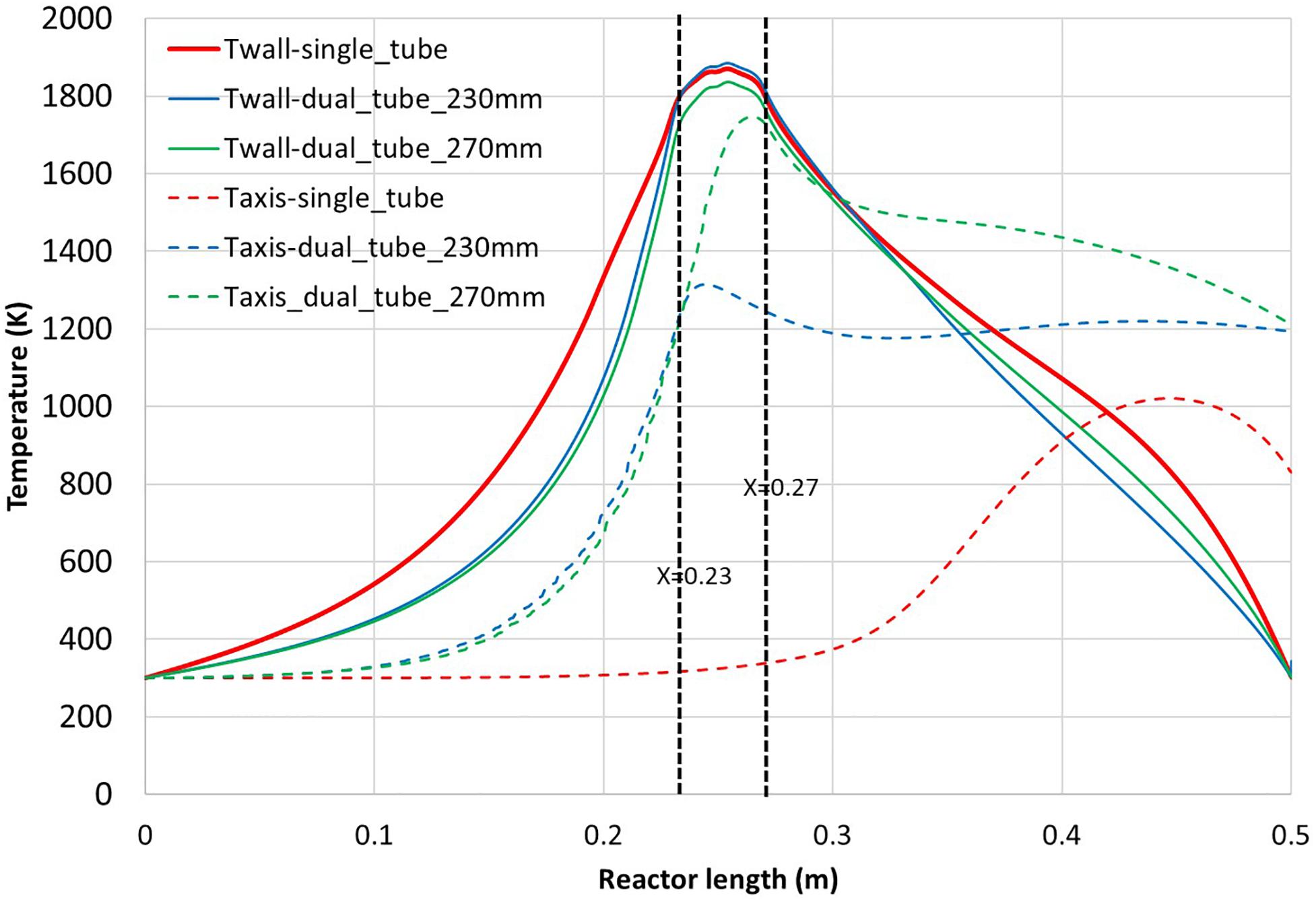
Figure 4. Temperature of the outer tube inner wall (continuous line) and on the symmetry axis (dashed line) for the three configurations (single tube, dual tube 270 mm, dual tube 230 mm length) vs. reactor length.
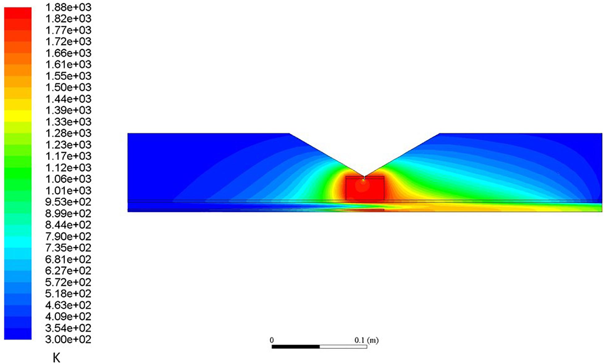
Figure 5. Temperature contour for the dual tube configuration (270 mm) (K).
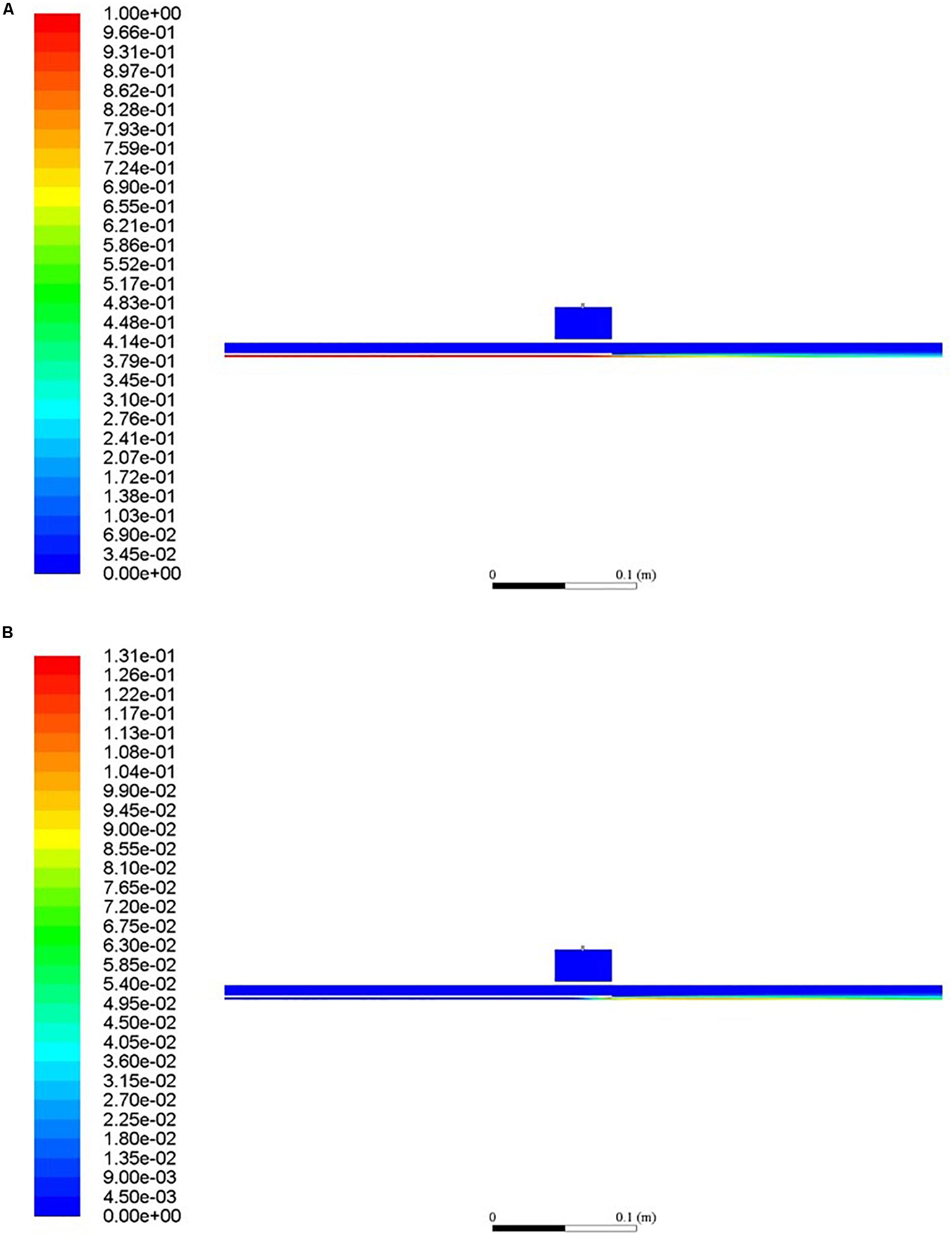
Figure 6. CH4 (A) and C (B) mass fraction for the dual tube configuration (270 mm).
Figure 7 reports the on-axis methane mole fraction and the methane conversion along the reactor axis. Concerning on-axis methane mole fraction, it is almost constant for the single tube (equal to the inlet mole fraction) because the on-axis temperature remains low with almost no cracking reaction. For the dual tube configuration, the on-axis mole fraction of methane decreases progressively due to both the mixing with argon and the hydrogen and carbon production. The 270 mm dual tube configuration shows a sharper decrease than the 230 mm dual tube configuration due to better methane conversion. It can be observed that the single tube configuration and the dual tube configuration (270 mm) reach similar conversion performance of 22%, while the dual tube configuration (230 mm) cannot convert methane because of too low gas temperatures (Figure 4). It can be seen that for the dual tube configuration (270 mm), 13% methane conversion is already reached at the innermost tube exit, which is not desirable since carbon deposition is expected on the walls. However, in this zone, high gas velocities could enhance carbon transportation. The maximum velocity value (see velocity contour in Supplementary Material 3) is below 25 m/s at the innermost tube outlet, resulting in a Reynolds number of about 200. The rest of the conversion occurs in the hot argon flow without reaching the outermost tube wall. The globally low conversion is mainly due to the fact that the residence time is too short. Indeed, high argon and methane flow lead to high gas velocities that in turn limit the maximum gas temperature and kinetics. Hence, a sensitivity study on the argon and methane flow is proposed in the following section with the objective to optimize the dual tube configuration (230 mm) that offers the best design for volumetric reaction.
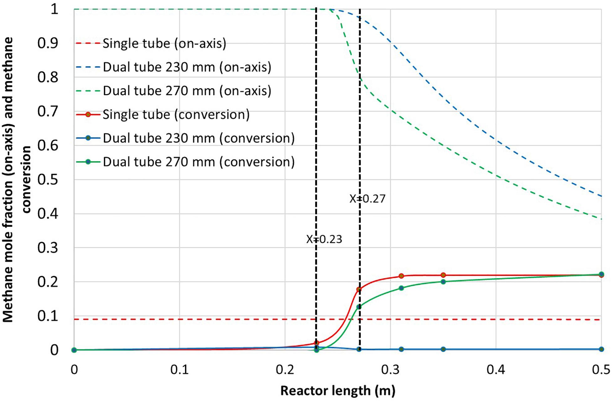
Figure 7. On-axis methane mole fraction along with methane conversion vs. reactor length for the three reactor configurations.
Flow-rates have been modified for the dual tube configuration (230 mm) in order to maximize the volumetric reaction and methane conversion. Argon and methane flow-rates have been studied.
In a first attempt, argon mass flow-rate was reduced from 2.3 × 10⁻⁴ kg.s–1 to 9.3 × 10⁻⁵ kg.s–1. Figure 8 shows the corresponding methane conversion and on-axis temperature. For a reduced argon flow-rate, the methane conversion reached 16% while almost no conversion was observed for the nominal argon flow-rate. Indeed, with a reduced argon flow-rate, the maximum on-axis temperature increased from 1315 to 1515 K, thereby improving kinetics and conversion. Increasing the temperature and reducing the gas residence time has been reported to be highly beneficial for the methane conversion (Rodat et al., 2010). Also, it can be observed that almost no conversion was obtained before the innermost tube exit (before X = 0.23 m). This means that the reaction mainly occurs in the free volume of hot argon. Moreover, a temperature increase is observed after X = 0.27 m due to mixing with the hot argon, playing the role of the flame. This high temperature zone corresponds closely to the increase in methane conversion (for 0.27 m < X < 0.37 m). Eventually, the on-axis temperature decreases faster toward the reactor exit for the lowest argon flow-rate due to reduced inertia of the gas flow and increased methane conversion (endothermic reaction). For the highest argon flow-rate, the on-axis outlet gas temperature is about 1200 K while it is lower than 550 K for the lowest argon flow-rate.
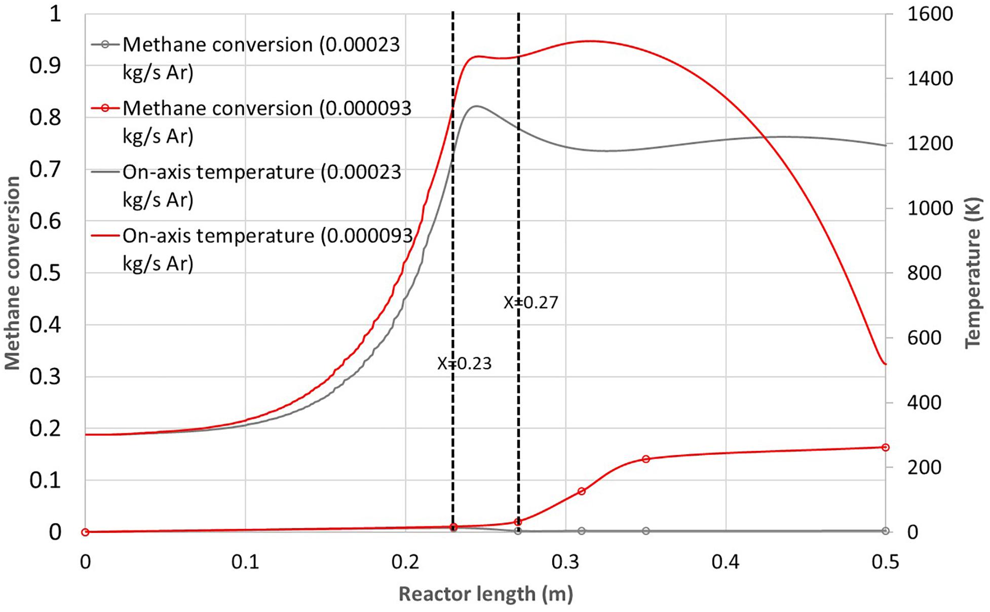
Figure 8. Methane conversion and on-axis temperature vs. reactor length for the 230 mm dual tube configuration and two different argon flow-rates (2.3 × 10– 4 kg.s– 1 and 9.3 × 10– 5 kg.s– 1).
In order to maintain sufficient argon flow to ensure volumetric reaction, the argon flow-rate was not reduced further and methane flow-rate was varied.
Three methane mass flow-rates were investigated for a constant argon mass flow-rate of 9.3 × 10⁻⁵ kg.s–1 (3.15 NL/min): 9.2 × 10⁻⁶ kg.s–1 (0.77 NL/min), 4.6 × 10⁻⁶ kg.s–1 (0.39 NL/min) and 2.3 × 10⁻⁶ kg.s–1 (0.19 NL/min). The results in terms of methane conversion and on-axis temperature are reported in Figure 9. The reduction of methane flow-rate enables to increase the on-axis temperature and consequently the methane conversion. The maximum temperature increases from 1515 to 1676 K and 1750 K for the respective methane flow-rates of 4.6 × 10⁻⁶ kg.s–1 and 2.3 × 10⁻⁶ kg.s–1. The corresponding conversions increase from 16% to 46% and 73%. However, it can be noticed that for the two smallest methane flow-rates, the maximum on-axis temperature is achieved in the innermost tube leading to up to 15% methane conversion in this tube, probably on the hot walls. Anyway, due to reduced residence time in the innermost tube, the conversion mostly occurs in the free volume between the innermost tube outlet and X = 0.35 m. Such dual-tube configuration has never been studied so far, thus experimental results are not yet available for validation. Anyway, for a single tube configuration with equivalent heating zone, Abanades et al. (2015) obtained a methane conversion of about 55% at a wall temperature of 1673 K for 0.2 NL/min of methane and 1.8 NL/min of argon. These results are consistent with the simulations which give 73% conversion for a methane flow-rate of 0.19 NL/min at a higher temperature (1950 K on the tube wall). Although the simulated argon flow-rate is 3.15 NL/min leading to a reduced residence time, the impact of temperature is predominant, which explains the higher conversion. Also, the dual tube configuration enhances heat transfer due to additional available surface for heat exchange. To improve further the methane conversion, argon preheating was evaluated through the use of the heating zone (Figure 1).
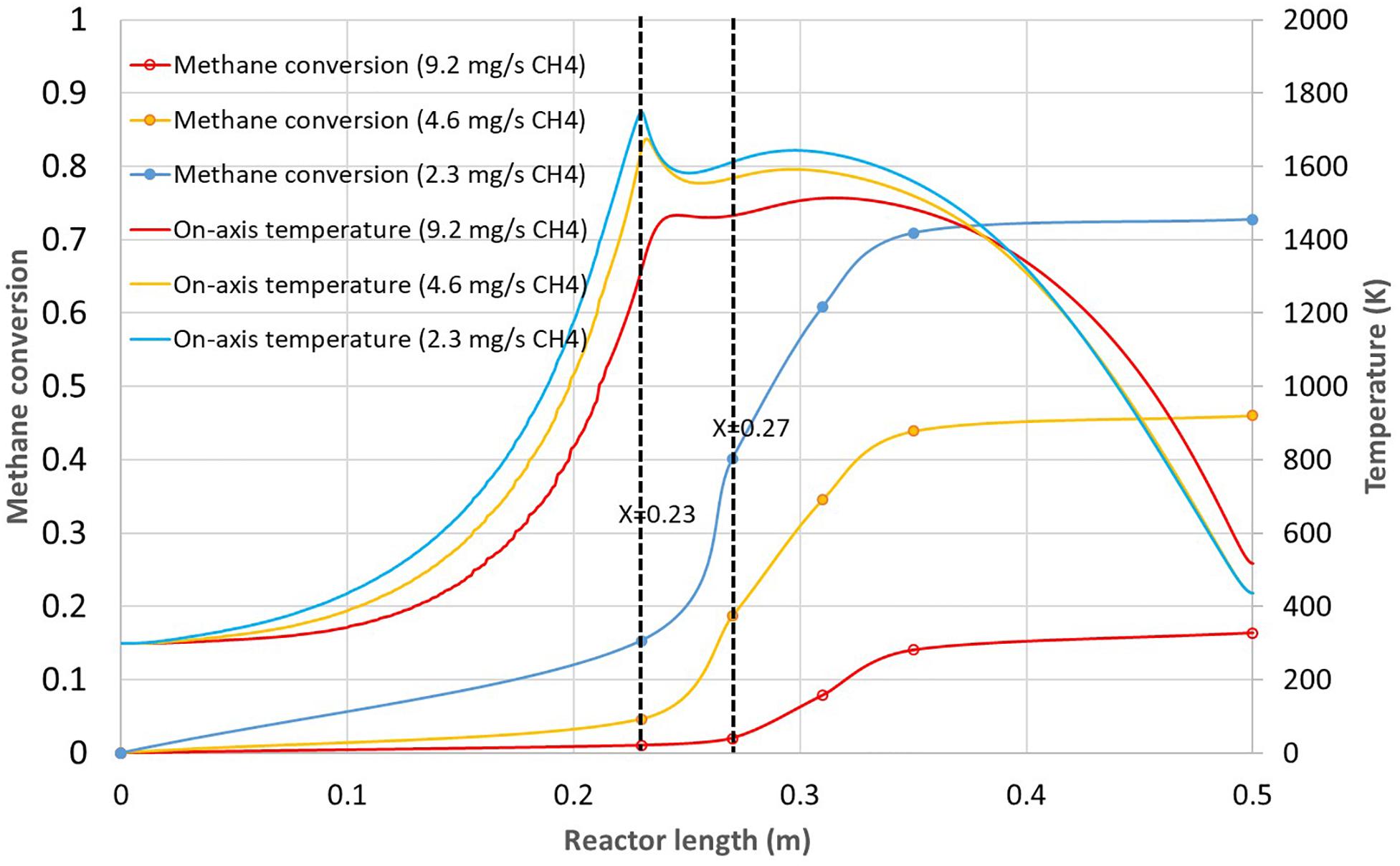
Figure 9. Methane conversion and on-axis temperature vs. reactor length for the 230 mm dual tube configuration and three different methane flow-rates (9.2 × 10⁻⁶ kg.s–1, 4.6 × 10– 6 kg.s– 1, and 2.3 × 10– 6 kg.s– 1).
In order to further improve methane conversion, the effect of argon preheating was investigated. For this purpose, the heating zone was implemented to bring additional power to the reactor (resistive electric heating is planned for the real concept). This way, the argon flow can theoretically be preheated up to the solar cavity temperature in case of solar irradiation decline and provide continuous process capability. As a first step, only argon preheating was simulated to evaluate its effect on the reactor performance. A power of 70 W was generated on the heating zone in addition to the solar input. Figure 10 reports the results in terms of methane conversion and on-axis temperature for the 230 mm dual tube configuration with and without preheating. The methane flow-rate is 4.6 × 10⁻⁶ kg.s–1 while the argon flow-rate is 9.3 × 10⁻⁵ kg.s–1. It can be observed that the maximum on-axis temperature increases from 1676 to 1800 K at the innermost tube outlet. At X = 0.3 m, the on-axis temperature is still about 50 K higher in case of preheating. This leads to an improvement in the final methane conversion from 46 to 77%. Methane is mainly converted in the free volume since the conversion at the exit of the innermost tube (X = 0.23 m) is only 5 and 17% without and with preheating, respectively. Going to higher power input would further increase the global methane conversion. However, as the preheating also preheats methane, methane conversion would also increase in the central tube, which is not desirable as the reaction may occur again on the walls. As a consequence, to increase the preheating power, a different design should be considered to limit cracking in the central tubular injector. A first option would be to reduce the innermost tube diameter to increase methane velocity. This would limit the methane residence time in the injector and thus its conversion. Another option would be to insert a L-shaped radial port for axial injection around X = 0.23 m, so that the methane flow temperature would be less affected by the preheating power. This technical option is more challenging in terms of fabrication because thermal dilatation has to be taken into account for proper design and operation. Nevertheless, these improved designs would enable a better control of the process and possible round the clock operation if the heating zone can provide sufficient power to compensate solar power decline. It is also possible to supply hot carrier gas from a thermal storage when solar power is decreasing. Eventually, the dynamic control of the reactor temperature is the next step required to reach continuous solar processes.
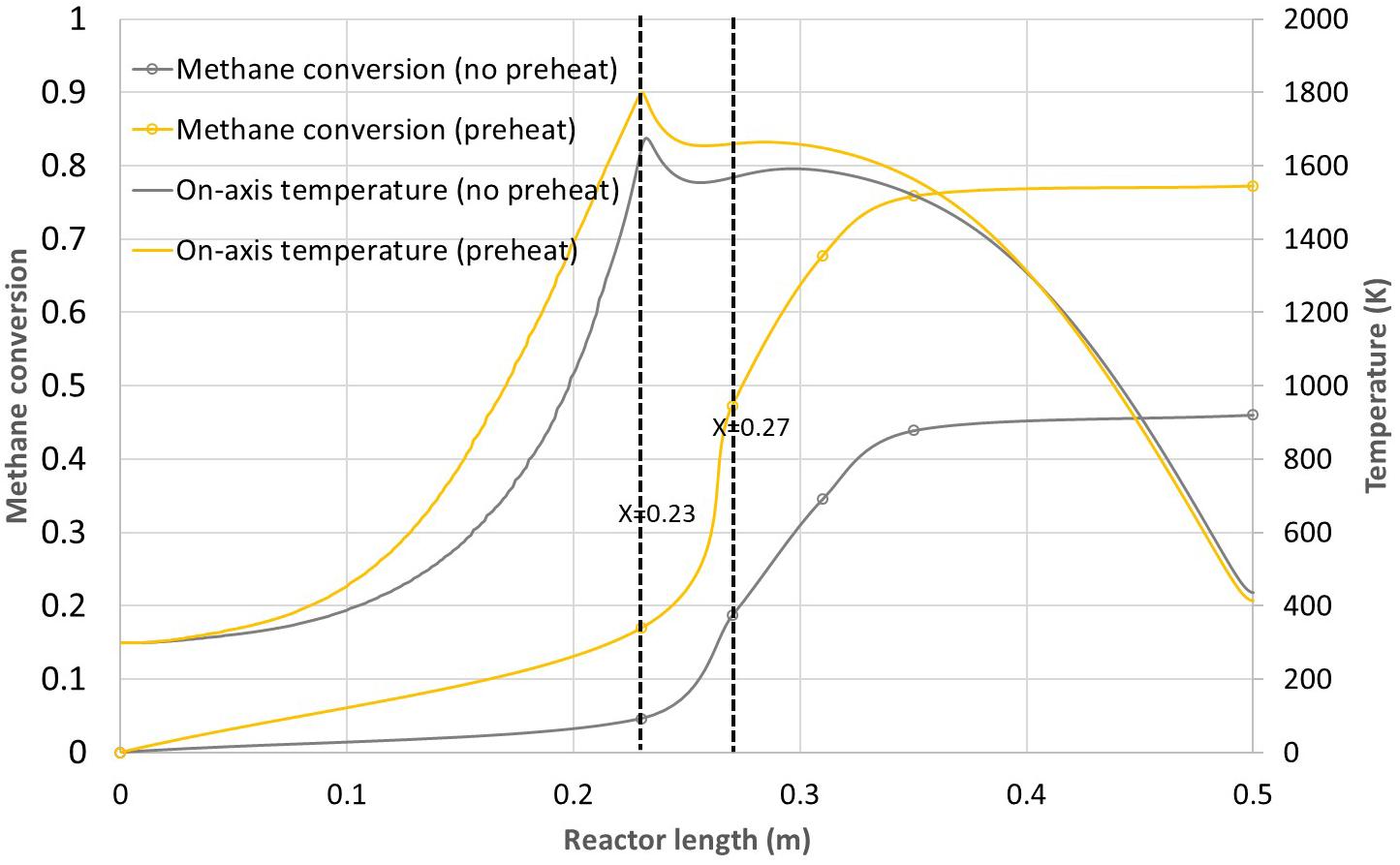
Figure 10. Methane conversion and on-axis temperature vs. reactor length for the 230 mm dual tube configuration with and without preheating.
A new windowless hybrid solar reactor was proposed for the volumetric methane thermal dissociation. It operates with a confined methane jet into a hot argon flow to reproduce a similar thermohydraulic behavior as in the conventional furnace black process. The CFD simulations enabled to optimize the design (tubes configuration and geometry) and the operating conditions (argon and methane flow-rates) to promote methane cracking in the free volume, avoiding carbon deposition issues on the tube walls. Furthermore, the use of an inert hot gas acting as a flame allows hybridizing the solar reactor for continuous operation at night, and simulations were carried out regarding the effect of argon preheating. The reported solar reactor design is the first of this kind and space remains for further optimization before bringing the concept to prototype. Methane conversion up to 77% was achieved at 1800 K with argon preheating, which proves the relevance of the design. Operating conditions and geometry can be further improved, for example by studying the impact of the innermost tube diameter or by replacing argon by nitrogen or even hydrogen. In addition, the injection could be inserted directly in the hot zone (via a L-shaped radial port for axial injection) to limit the cracking reaction in the innermost tube. Basically, this work demonstrates the relevance of the solar flame concept and opens the way for various applications conventionally relying on fossil fuels combustion such as reforming or metallurgy. The concept offers the opportunity for continuous round the clock operation of high temperature solar processes through heat storage or hybridization and dynamic control.
All datasets presented in this study are included in the article/Supplementary Material.
SR did the simulation work. SA and SR analyzed the results and wrote the manuscript. Both authors contributed to the article and approved the submitted version.
The authors declare that the research was conducted in the absence of any commercial or financial relationships that could be construed as a potential conflict of interest.
The Supplementary Material for this article can be found online at: https://www.frontiersin.org/articles/10.3389/fenrg.2020.00206/full#supplementary-material
Abánades, A., Rubbia, C., and Salmieri, D. (2012). Technological challenges for industrial development of hydrogen production based on methane cracking. Energy 46, 359–363. doi: 10.1016/j.energy.2012.08.015
Abánades, A., Ruiz, E., Ferruelo, E. M., Hernández, F., Cabanillas, A., Martínez-Val, J. M., et al. (2011). Experimental analysis of direct thermal methane cracking. Int. J. Hydrog. Energy 36, 12877–12886. doi: 10.1016/j.ijhydene.2011.07.081
Abanades, S., and Flamant, G. (2008). Hydrogen production from solar thermal dissociation of methane in a high-temperature fluid-wall chemical reactor. Chem. Eng. Process. Process Intensif. 47, 490–498. doi: 10.1016/j.cep.2007.01.006
Abanades, S., Kimura, H., and Otsuka, H. (2015). A drop-tube particle-entrained flow solar reactor applied to thermal methane splitting for hydrogen production. Fuel 153, 56–66. doi: 10.1016/j.fuel.2015.02.103
Abbas, H. F., and Wan Daud, W. M. A. (2010). Hydrogen production by methane decomposition: a review. Int. J. Hydrog. Energy 35, 1160–1190. doi: 10.1016/j.ijhydene.2009.11.036
Afroughi, M. J., Falahati, F., Kostiuk, L. W., and Olfert, J. S. (2019). Properties of carbon black produced by the thermal decomposition of methane in the products of premixed flames. J. Aerosol Sci. 131, 13–27. doi: 10.1016/j.jaerosci.2019.02.002
Arastoopour, H. (2019). The critical contribution of chemical engineering to a pathway to sustainability. Chem. Eng. Sci. 203, 247–258. doi: 10.1016/j.ces.2019.03.069
Chinnici, A., Nathan, G. J., and Dally, B. B. (2018). Experimental demonstration of the hybrid solar receiver combustor. Appl. Energy 224, 426–437. doi: 10.1016/j.apenergy.2018.05.021
da Costa Labanca, A. R. (2020). Carbon black and hydrogen production process analysis. Int. J. Hydrog. Energy [Epub ahead of print]. doi: 10.1016/j.ijhydene.2020.03.081
Geißler, T., Abánades, A., Heinzel, A., Mehravaran, K., Müller, G., Rathnam, R. K., et al. (2016). Hydrogen production via methane pyrolysis in a liquid metal bubble column reactor with a packed bed. Chem. Eng. J. 299, 192–200. doi: 10.1016/j.cej.2016.04.066
Gore, R., and Crowe, C. (1988). “Observations on the flow in a confined coaxial jet,” in Proceedings of the 1st National Fluid Dynamics Conference, (Cincinnati,OH: American Institute of Aeronautics and Astronautics).
Javadi, M., Moghiman, M., and Pishbin, I. (2010). The Effect of H2S on Hydrogen and Carbon Black Production from Thermal Decomposition of Sour Natural Gas. London: IntechOpen.
Kogan, A., Israeli, M., and Alcobi, E. (2007). Production of hydrogen and carbon by solar thermal methane splitting. IV. Preliminary simulation of a confined tornado flow configuration by computational fluid dynamics. Int. J. Hydrog. Energy 32, 4800–4810. doi: 10.1016/j.ijhydene.2007.08.016
Maag, G., Lipiński, W., and Steinfeld, A. (2009). Particle–gas reacting flow under concentrated solar irradiation. Int. J. Heat Mass Transf. 52, 4997–5004. doi: 10.1016/j.ijheatmasstransfer.2009.02.049
Ozalp, N., Epstein, M., Davis, R., Ophoff, C., and Vinck, I. (2018). A critical assessment of present hydrogen production techniques: is solar cracking a viable alternative? Curr. Opin. Chem. Eng. 21, 111–115. doi: 10.1016/j.coche.2018.10.001
Ozalp, N., Kogan, A., and Epstein, M. (2009). Solar decomposition of fossil fuels as an option for sustainability. Int. J. Hydrog. Energy 34, 710–720. doi: 10.1016/j.ijhydene.2008.11.019
Rodat, S., Abanades, S., and Flamant, G. (2017). US9784473B2 Solar System for Reproducing the Effect of a Combustion Flame.
Rodat, S., Abanades, S., Sans, J.-L., and Flamant, G. (2009). Hydrogen production from solar thermal dissociation of natural gas: development of a 10kW solar chemical reactor prototype. Sol. Energy 83, 1599–1610. doi: 10.1016/j.solener.2009.05.010
Rodat, S., Abanades, S., and Flamant, G. (2011). Methane decarbonization in indirect heating solar reactors of 20 and 50 kW for a CO2-free production of hydrogen and carbon black. J. Sol. Energy Eng. 133:031001. doi: 10.1115/1.4004238
Rodat, S., Abanades, S., Sans, J.-L., and Flamant, G. (2010). A pilot-scale solar reactor for the production of hydrogen and carbon black from methane splitting. Int. J. Hydrog. Energy 35, 7748–7758. doi: 10.1016/j.ijhydene.2010.05.057
Rowe, S. C., Hischier, I., Palumbo, A. W., Chubukov, B. A., Wallace, M. A., Viger, R., et al. (2018). Nowcasting, predictive control, and feedback control for temperature regulation in a novel hybrid solar-electric reactor for continuous solar-thermal chemical processing. Sol. Energy 174, 474–488. doi: 10.1016/j.solener.2018.09.005
Shpilrain, E., Shterenberg, V., and Zaichenko, V. (1999). Comparative analysis of different natural gas pyrolysis methods. Int. J. Hydrog. Energy 24, 613–624. doi: 10.1016/S0360-3199(98)00114-111
Weger, L., Abánades, A., and Butler, T. (2017). Methane cracking as a bridge technology to the hydrogen economy. Int. J. Hydrog. Energy 42, 720–731. doi: 10.1016/j.ijhydene.2016.11.029
Keywords: solar reactor, methane cracking, hydrogen, carbon black, hybridization, solar flame
Citation: Rodat S and Abanades S (2020) A Hybrid Windowless Dual Tube Solar Reactor for Continuous Volumetric Natural Gas Dissociation. Front. Energy Res. 8:206. doi: 10.3389/fenrg.2020.00206
Received: 16 June 2020; Accepted: 31 July 2020;
Published: 28 August 2020.
Edited by:
Bamidele Victor Ayodele, Universiti Tenaga Nasional, MalaysiaReviewed by:
Sharanjit Singh, Tsinghua University, ChinaCopyright © 2020 Rodat and Abanades. This is an open-access article distributed under the terms of the Creative Commons Attribution License (CC BY). The use, distribution or reproduction in other forums is permitted, provided the original author(s) and the copyright owner(s) are credited and that the original publication in this journal is cited, in accordance with accepted academic practice. No use, distribution or reproduction is permitted which does not comply with these terms.
*Correspondence: Sylvain Rodat, c3lsdmFpbi5yb2RhdEBwcm9tZXMuY25ycy5mcg==
Disclaimer: All claims expressed in this article are solely those of the authors and do not necessarily represent those of their affiliated organizations, or those of the publisher, the editors and the reviewers. Any product that may be evaluated in this article or claim that may be made by its manufacturer is not guaranteed or endorsed by the publisher.
Research integrity at Frontiers
Learn more about the work of our research integrity team to safeguard the quality of each article we publish.