 Dongsheng Qiao
 Changlong Feng
 Dezhi Ning
 Chang Wang2
 Haizhi Liang
95% of researchers rate our articles as excellent or good
Learn more about the work of our research integrity team to safeguard the quality of each article we publish.
Find out more
ORIGINAL RESEARCH article
Front. Energy Res. , 31 March 2020
Sec. Process and Energy Systems Engineering
Volume 8 - 2020 | https://doi.org/10.3389/fenrg.2020.00042
This article is part of the Research Topic Advances and Challenges in Ocean Wave Energy Harvesting View all 8 articles
For the marginal oilfield with low oil extraction, adding wave energy conversion device integration to the jacket platform is very meaningful for reducing the mining cost. First, the design concept of integrated oscillating water column (OWC) device with jacket platform is proposed. Then, the optimal model of OWC device structural arrangement parameters is established with the aim of low wave force and high wave energy conversion efficiency. Finally, the dynamic response of the integrated device is analyzed under the working and extreme sea states. The results show that the integrated device has certain effectiveness and feasibility.
With the development of society, the demand for energy continues to increase, and the reserves of conventional petrochemical energy such as coal and oil are decreasing, and the energy crisis is increasing (Cheng et al., 2009). At the same time, environmental pollution, and protection pressures have gradually increased. In recent years, the smoggy weather has increased more and more, indicating the importance of developing clean energy. The ocean, which accounts for 70% of the Earth's surface area, contains abundant clean energy. Among them, ocean wave energy is a kind of energy converted by wind energy. The wind blows across the ocean and transfers the energy to the sea water through the sea–air interaction, forming waves and storing the energy as potential energy (the potential of water mass away from the sea level) and kinetic energy (water motion) (Liu and Ma, 2018). Wave energy has wide distribution and high energy density. It has a periodic law, which is convenient for standardized development and utilization (Tidwell and Weir, 2006). The wave energy, which is the highest quality energy in the ocean, can be converted into electricity if properly utilized.
There are many types of wave energy conversion devices, more than thousands of patents. At present, wave energy conversion devices have entered the stage of industrialization and practical application demonstration; in recent decades, the world has built wave energy conversion demonstration devices, more than 30 practical devices, and some devices have entered commercial operation stage (Gao, 2012), for example, the 500-kW wave power station established in Portugal with an average power of 124 kW and a maximum of 525 kW, the 500-kW wave power station built in Norway, and the LIMPET500 built in Scotland, United Kingdom, located on the island of Islay with an energy flow density of 15–25 kW/m (Yu, 1993; Teixeira et al., 2013; Ji, 2017). At present, many countries in Asia, Europe, and America are striving to research and develop cutting-edge technologies for various wave conversion devices. At present, commonly used wave energy converter (WEC) types include oscillating water column (OWC), oscillating wave surge converters (OWSC), mechanical transmission, hydraulic, and overtopping (Scruggs, 2009; Renzi and Dias, 2013; Michele et al., 2017, 2019a; Michele and Renzi, 2019).
OWC structures were proposed by Yoshio Masuda for the first time in 1940 and was applied in a navigation buoy (Falcão, 2009). Based on the linear wave theory and rigid body hypothesis, Evans (1976, 1982) simplified OWC water column into a rigid piston vibrating with one degree of freedom and proposed the theoretical model of OWC hydrodynamics for the first time. As the most commercial development form of WECs at present, a large number of investigations have concentrated on increasing the hydrodynamic efficiency of the OWC devices, usually by changing the geometric shape and structure of the OWC devices, using numerical and experimental methods. Ambli et al. (1982) proposed a kind of multiresonance oscillating water column device with a port added in front of the air chamber, and the effect of resonance wave on incident wave and water column in the air chamber is studied by model test. Korde (1991) improved on the traditional OWC device so that waves can achieve resonance in the device, thus overcoming the disadvantage that the intrinsic period of the traditional OWC device is smaller than the wave period and the wave energy conversion efficiency is low. Boccotti (2006) proposed a new type of U-shaped OWC structure, and its inherent period is larger and the utilization efficiency of wave energy is higher compared with the traditional OWC device. Dizadji and Sajadian (2011) studied the influence of geometry parameters of OWC on the wave energy conversion efficiency through the flume test, including angles of the front and rear wall of the air chamber, position and diameter of the air outlet pipe, and the width of the air chamber at the pipe position. Chang et al. (2016) developed an experiment to investigate the influence of the angle of the back wall, the front wall, and the chamber width on the hydrodynamic performance of OWC devices. He and Huang (2017) studied the characteristics of orifices for modeling non-linear power takeoff of OWC. The hydrodynamic performance of an array of OWCs installed along a vertical straight coast was evaluated by Zheng et al. (2019). Ning et al. (2019) analyzed the wave energy conversion efficiency of an OWC under various stepped bottom configurations. He et al. (2019) adopted a local increase in the back-wall draft of pile-supported OWC to enhance wave power extraction and reduce wave transmission. A mathematical model is developed to analyze the hydrodynamics of a novel OWC with a coaxial cylindrical structure in a hybrid wind-wave energy system by Michele et al. (2019b), and their analytical results showed excellent agreements with the experimental analyses of Perez-Collazo et al. (2018).
Contrasting to OWC devices with a single chamber, it is suggested that significant increases in energy extraction can be achieved from dual-chamber devices. Dual-chamber devices were installed on a floating breakwater for wave energy extraction by He et al. (2012, 2013). A dual-chamber OWC-WEC, which has two subchambers with a shared orifice, was proposed by Ning et al. (2017), and the effects of the chamber geometry on the variation of surface elevation and water column volume in the two subchambers were studied. He et al. (2017) accurately measure the wave power of floating OWC with wider chamber breadth in the experiments for the first time and discussed the power extraction performance of a floating breakwater with dual-chamber devices. Ahmed et al. (2018) investigated the hydrodynamic performance of various dual-chamber offshore-stationary OWC-WECs, using well-validated 2D and 3D computational fluid dynamics (CFD) models based on the Reynolds-averaged Navier–Stokes equations (RANS) equations and the volume of fluid (VOF) method and compares the results to single-chamber OWC devices. Ning et al. (2018) proposed a novel cylindrical OWC-WEC with double chambers to harvest the wave energy effectively in deep water, and investigated its hydrodynamic characteristics by an analytical model based on the linear potential flow theory and eigenfunction expansion technique.
As a high-cost energy resource, improving the efficiency of wave energy converters is one of the important ways to reduce the operational expense. Applying the concept of cost sharing, some investigations concentrated on the integration of WECs into coastal and offshore structures, such as breakwaters, jetties, or along sections of the coast, presenting an effective way to significantly increase the wave power exploitation. Integrating OWCs into caisson breakwater makes it able to generate electricity while dissipating the waves (He and Huang, 2014, 2016). For this combined structure, Boccotti (2007), Boccotti et al. (2007), Shi and Yang (2010), and Qin et al. (2013) conducted related investigations. Sarkar et al. (2015) and Michele et al. (2016) carried out investigations on hydrodynamics and performance of OWSCs with a straight coast. He et al. (2016) discussed the performances of both wave energy extraction and vortex-induced energy loss for the combined OWC breakwater. As offshore platforms developing into the deeper ocean, the problem of electricity consumption for the operation of offshore platforms needs to be solved. Integrating the WECs into platforms can convert the clean energy wave energy into electric energy, provide power for the normal operation production of platform, improve economic benefits of oil exploitation, and alleviate the current situation of energy shortage. At present, taking a jacket platform for example, the design concepts of the integrated device mainly have the following types: the OWC device, the oscillating floating buoy device, and the overtopping device (Ji, 2017).
In this paper, an integrated OWC device integrated into the jacket platform is proposed, and the dynamic response analysis is conducted. First, the concept design of the integrated device is proposed, and the ANSYS finite element model is established based on a jacket platform. The calculation of wind, wave, and current load is carried out, and the calculation method of structural dynamic response is clarified. Then, the optimization function model is used to explore the optimal structural parameters of the OWC device. The wave force and its wave energy conversion efficiency coefficient of the OWC device is obtained by giving a series of device drafts and chamber radiuses. Based on the optimal objective function with the smallest wave force and highest wave energy conversion efficiency of OWC, the optimal structural parameters of the OWC device are obtained. Finally, the OWC device with the optimal structural parameters is integrated into the jacket platform, and the dynamic responses under different load conditions are carried out, and the results are also compared with the jacket platform without the integrating OWC device.
This paper proposes an integrated OWC conversion device for the jacket platform by Dalian University of Technology. The structure diagram is shown in Figure 1, where for the convenience of drawing, the actual oblique angle of jacket platform legs is not shown, and the oblique angle is very small, which has very little influences on the wave loads of the integrated device. The device is divided into two parts: a jacket platform and a wave energy conversion device. The wave energy conversion device consists of an air chamber and an air turbine generator. The air chamber is a combination of cylindrical ring body and hemispherical ring body with same radius; the upper part of the hemisphere ring body is provided with a vent hole pipe, which is connected with an air turbine device that rotates in the same direction under the action of two-way airflow; the upper part of air chamber is welded to the pile foundation, thereby maximally securing the space of the air chamber. The device in this paper can capture wave energy in 360°; thus, the absorption rate of wave energy could be improved. The fixed structure is used to ensure the stability of the device. Thus, it is possible to integrate the device into the jacket platform, which can provide electricity for the operation and production process.
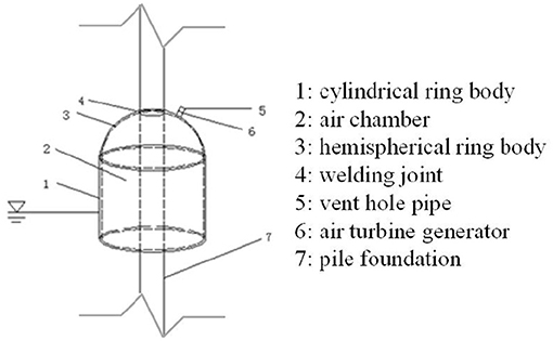
Figure 1. Device sketch.
The finite element model of the jacket platform is established as shown in Figure 2, which is based on the jacket platform in JZ-20 oil field in Jinzhou, Liaoning province in China. The environmental loads, including wind, wave, and current, are calculated in this section, and then, they are applied into the established finite element model to calculate the dynamic responses. According to the design data, the height from the water surface to the top deck of the platform is 15 m, and the OWC device is installed on the legs and submerged with a draft depth d.
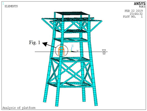
Figure 2. Finite element model.
The wind loads f wind can be calculated by the following formula (Li, 2012):
where the air density ρA is taken as 1.293; AW is the projected area of the structure perpendicular to the direction of wind, taken as 1,810.73 m2 based on design data; UW is the average wind velocity, which is usually taken at 10 m on the water surface; and CD is the wind pressure coefficient.
Ignoring the interaction with the remaining OWCs and the jacket platform, the wave force acting on a single OWC, as shown in Figure 1, is calculated by the analytical solutions using the linear potential-flow theory and eigenfunction expansion technique, referenced by the established model of authors (Zhou et al., 2018), which is also similar with Michele and Renzi (2019). The part below the water surface of the wave energy conversion device can be simplified as shown in Figure 3. h is the water depth; d is the draft depth of outdoor wall of air chamber; and R1, R2, and R3 are the radiuses of the cylinder, inner wall, and outer wall of air chamber. The Cartesian coordinate system is taken, with the still water surface set as the coordinate plane and the ordinate axis passing through the center of the air chamber. The computational domain of fluid is divided into three subdomains: outer domain Ω1, medium domain Ω2, and inner domain Ω3.
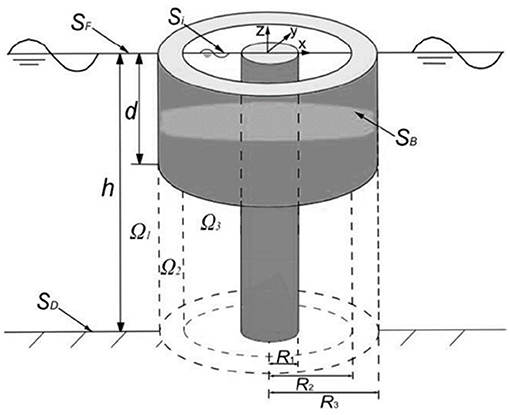
Figure 3. Underwater part schematic.
The air in the chamber is considered to be motion isentropic and compressible, and all of the time-dependent variables are assumed to be harmonic. Thus, the air pressure p in the chamber is:
where ω is the wave angular frequency, p0 is the complex amplitude of the pressure, Re[·] is the real part, t is the time, and .
A Wells turbine is installed at the top of the air chamber, and the mass flux rate of air across the turbine is proportional to the air pressure, and within the framework of a linear theory, the relationship between the turbine characteristics and the air mass flux is:
where q0 is the amplitude of air volume flux, K is an empirical coefficient depending on the design of the OWC turbines, D is the diameter of turbine rotor, N is the rotational speed of turbine, V0 is the volume of air in the chamber, ca is the speed of sound, and ρa is the air density.
Based on the linear theory, the volume flux of the chamber is the sum of volume fluxes as a result of wave radiation and diffraction. The wave radiation is caused by the wave motion purely generated by the oscillating air pressure of the chamber. The wave diffraction is caused by the scattering of incident waves when the air pressures are identical inside and outside of the chamber. Thus, the complex amplitude of volume flux q0 is:
where qR and qD are the radiation and diffraction solutions, respectively. For the radiation solution, an added mass coefficient C and damping coefficient B can be obtained (Evans, 1976, 1982), so the amplitude of volume flux qR is:
Through substituting Equations (4) and (5) into Equation (3), the air pressure in the chamber can be obtained:
where qD is the wave diffraction solution, and B and C can be obtained through the radiation problem solution under the unit forced pressure.
The fluid is assumed as incompressible, inviscid, and flow irrotational; the solution of boundary value problem shown in Figure 3 is considered. For small amplitude wave, the velocity potential ϕ(x, y, z, t) around the structure satisfies the linearized boundary value:
where n is the normal derivative to the corresponding surface, and g is the gravity acceleration. σR is a switch between the diffraction and radiation solution. For the radiation solution, σR = 1 is set, and the pressure amplitude in chamber is p0 = 1 in Equation (2). For the diffraction solution, σR = 0 is set.
Under a regular wave with an incident angular frequency ω, the time factor can be separated from the velocity potential using the perturbation expansion theory:
The boundary value problems in the computational domains Ω1, Ω2, and Ω3 can be founded, respectively, according to Equations (7)–(10), and based on the linear potential-flow theory and eigenfunction expansion technique, the potential function on each computational domain φi (i = 1, 2, 3) and the diffraction and radiation components , can be obtained. The amplitude of volume flux can be calculated using the free-surface integration:
where and are the diffraction and radiation components of φ3.
Then, the wave force on the OWC device can be calculated:
Assuming that the current profile is uniform, the current loads fcurrent can be calculated by the following formula (Li, 2012):
where ρc is the fluid density, taken as 1,025 kg/m3; Ac is the projected area of the structure perpendicular to the direction of current, taken as 93 m2 based on design data; Uc is the velocity of current; and CD is the current drag coefficient.
The wind and wave directions are all along the positive direction of X-axis. The depth of six times the pile diameter below the mud line is regarded as rigid fixed constraint. The dynamic analysis of the jacket platform is carried out under the working conditions (wind velocity is 19.6 m/s, current velocity is 1.5 m/s, wave height is 1.8 m, and wave period is 5.4 s) and extreme conditions (wind velocity is 31.7 m/s, current velocity is 2.0 m/s, wave height is 4.4 m, and wave period is 8.1 s), which are obtained from the design data of JZ-20. The ANSYS software is used to calculate the displacement, velocity, and acceleration responses of the top node of jacket platform (as shown in Figure 2). The calculation results are shown in Table 1.
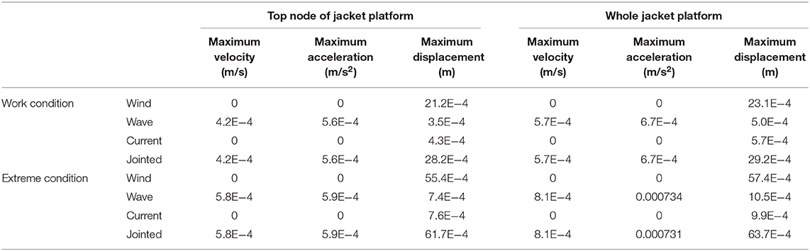
Table 1. Dynamic responses under different load conditions.
According to Table 1, under the working condition, the displacement caused by wind load accounts ~75% of the total displacement caused by the jointed action of wind–wave–current. Meanwhile, under the extreme condition, the displacement caused by wind load accounts ~89.8% of the total displacement. Thus, the contribution of wind load dominates the total displacement response of structure, and the contributions of current and wave load on the displacement response are nearly the same, with both accounting for <12%. Owing to the wind and current load set as the constant loads during the calculation, the velocity and acceleration responses are 0, and the velocity and acceleration responses of the structure are all caused by wave load.
To apply the OWC device integrated to the jacket platform in engineering practice, the reasonable structural parameters of OWC device are needed to be determined based on the actual sea conditions. The optimization criteria are set as follows: the device is subjected to the minimum wave force while the device has the highest wave energy capture efficiency.
According to the design data of the jacket platform in the sea area, the diameter of pile legs and wave conditions of the sea area have been determined. Considering the air chamber radius d1 = R2 − R1 and the draft depth of device d, the effects of structural parameters on the wave energy capture efficiency of OWC device and the corresponding subjected wave force are studied. As shown in Figure 4, the water depth h is taken as 15.0 m, d2 = R3 − R2 = 0.1 m, and the radius of the intermediate pile R1 is 0.75 m according to the design drawing of jacket platform.
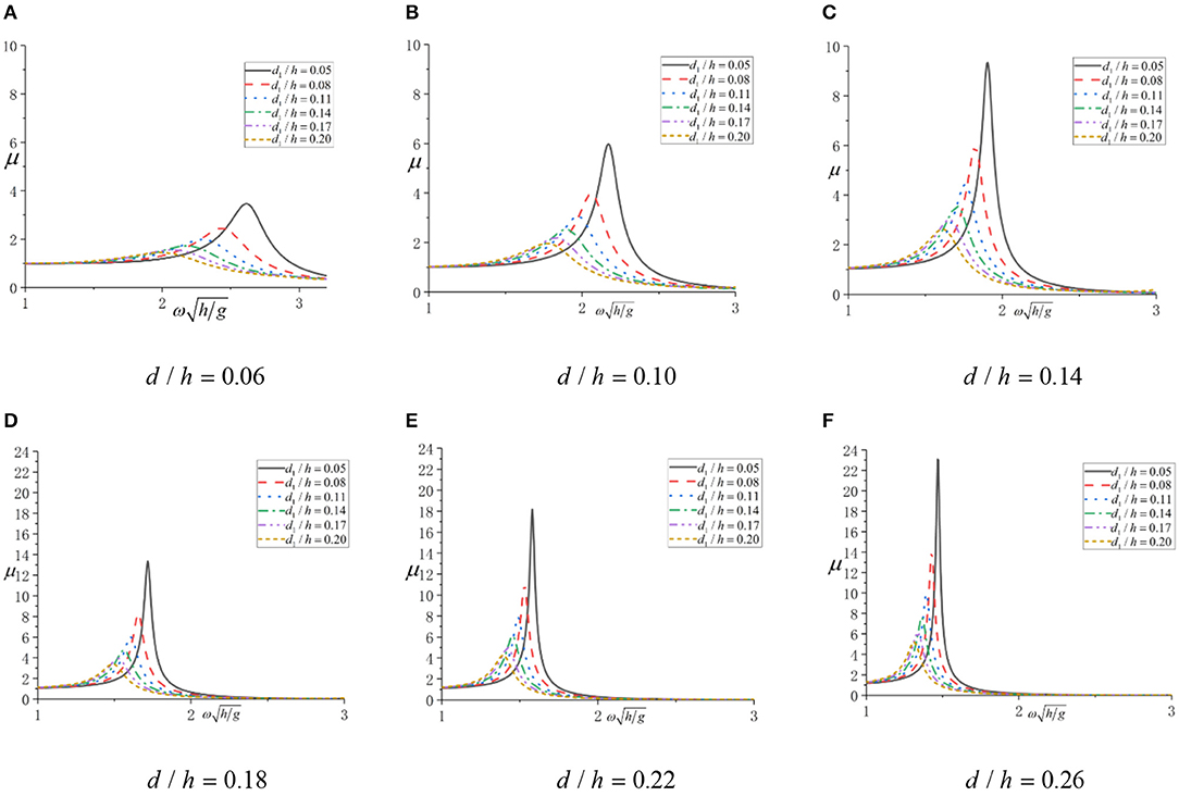
Figure 4. Wave energy capture efficiency under different oscillating water column (OWC) structural parameters. (A) d/h = 0.06; (B) d/h = 0.10; (C) d/h = 0.14; (D) d/h = 0.18; (E) d/h = 0.22; (F) d/h = 0.26.
To achieve the minimum wave force and the highest wave energy capture efficiency, the draft depth d and the air chamber radius d1 = R2 − R1 are chosen as the optimized variables, and the structural parameter optimization model of OWC device is established.
Based on the optimization model above, series values of draft depth d and chamber radius d1 are given according to the practice project. The wave force F and wave energy capture efficiency μ under different combinations of d and d1 are calculated, respectively, and then, the optimal values are determined based on the calculation results. The wave force F can be calculated by Equation (13), and the wave energy capture efficiency μ is defined as follows (Zhou et al., 2018):
where Po is the time-averaged value of power captured by OWC device, ρ is the water density, A is the wave amplitude of incident wave, Cg is the group velocity of incident wave, and k is the incident wave number.
Thus, the optimization objective function is as follows:
The constraint conditions are the following:
For each combination of draft depth and air chamber radius, a series of incident wave frequency ω values are given, and the corresponding wave force and wave energy capture efficiency of each combination can be obtained as a function of ω. The draft depth d, the air chamber radius d1, and the wave force F are non-dimensionalized, as shown in Table 2.
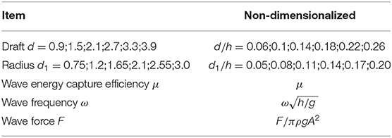
Table 2. Non-dimensionalized parameters.
The results of wave energy capture efficiency under different chamber radius, draft depth, and wave frequencies are shown in Figure 4. The results of wave force are shown in Figure 5.
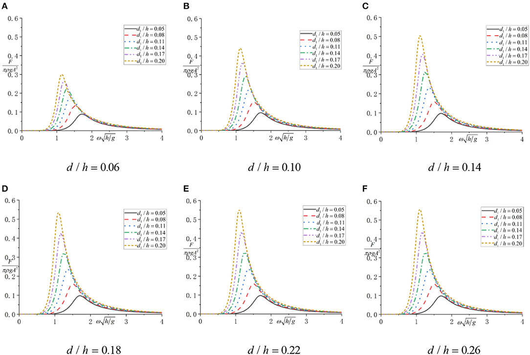
Figure 5. Wave force under different oscillating water column (OWC) structural parameters. (A) d/h = 0.06; (B) d/h = 0.10; (C) d/h = 0.14; (D) d/h = 0.18; (E) d/h = 0.22; (F) d/h = 0.26.
According to Figure 4, under each combination of draft depth and chamber radius, the wave energy capture efficiency increases from 1 to the maximum and then decreases to 0 as the incident wave frequency increases. The smaller radius could make the incident wave frequency, which generates maximum wave energy capture efficiency, become larger. The reason of wave energy capture efficiency initially starting from 1 is that the incident wave frequency is in the region of low frequency long wave, and the wave length is much larger than the geometry size of OWC device, so the wave surface in the air chamber cannot be affected by the interface wave. The frequency corresponding to the maximum wave energy capture efficiency is exactly equal as the incident wave frequency when the piston resonance motion occurs in the OWC device.
According to Figure 5, under each combination of draft depth and chamber radius, the wave force increases from 0 to the maximum value and then decreases to 0 as the incident wave frequency increases. The larger draft depth could make the incident wave frequency that generates maximum wave force become smaller.
In summary, when the draft depth is constant, the smaller air chamber radius could make the resonance frequency of incident wave and wave energy capture efficiency become larger and make the wave force become smaller. Therefore, the slenderer the air chamber, the better the wave energy capture efficiency and the smaller the wave force. However, when the air chamber radius is constant, the larger is the draft depth, the larger is the maximum wave energy capture efficiency at the resonance frequency, and the larger is the wave force. In a word, the optimization objective function needs to be solved aiming to get the optimal OWC structure parameters.
For the optimization objective function Equation (17) shown above, when the wave energy capture efficiency coefficient μ reaches the maximum value, the wave force F is not exactly the minimum value. Therefore, the two optimization objective functions are combined into one:
Based on the calculation results shown above, the optimization objective function of Equation (19) is solved and shown in Figure 6.
Figure 6. F/μ of oscillating water column (OWC). (A) d/h = 0.06; (B) d/h = 0.10; (C) d/h = 0.14; (D) d/h = 0.18; (E) d/h = 0.22; (F) d/h = 0.26.
According to Figure 6, under each combination of draft and chamber radius, the F/μ increases from 0 to the maximum value and then decreases to 0 as the incident wave frequency increases. The smaller the air chamber radius, the smaller the F/μ value, and the smaller the resonance frequency of incident wave. Therefore, to solve the optimization objective function, it could be simply achieved through finding the minimum value of F/μ in each diagram of Figure 6 under different cases.
Based on the design data of the jacket platform shown in Dynamic Response Calculation above, the wave period of working conditions is 5.4 s, so the non-dimensionalized wave frequency is 1.424. In each diagram of Figure 6, the value of F/μ is the smallest when d1/h = 0.05, and the results corresponding to different draft depths are shown in Table 3.
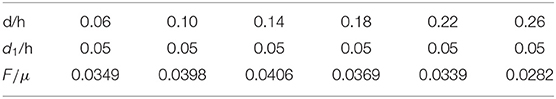
Table 3. Minimum value of F/μ for working conditions.
According to Table 3, the minimum value of F/μ for working conditions increases first and then decreases. The minimum value is 0.0282, and the corresponding structural parameter of OWC device is d/h = 0.26, that is, the draft depth is 3.9 m, and the air chamber radius is 0.75 m. This is the optimal OWC device structural parameters under the working condition. If the OWC wave energy conversion device is installed in the other sea area, the optimal structural parameters could also simply be selected based on the wave frequency and Figure 6.
Based on the optimal structural parameters of the OWC device under the working conditions shown above, the device could be integrated into the jacket platform, and the influence of integration on the dynamic response of platform is analyzed.
Under the combined action of wind, wave, and current, considering the working conditions, and extreme working conditions, the dynamic response of the jacket platform with and without OWC device is calculated. The influence of OWC device integration on the dynamic response of the jacket platform is studied to provide references for actual construction of project.
Under the action of working condition with regular waves, the time histories of dynamic response of top node of the jacket platform integrated with OWC device (Node No. 1095, shown in Figure 2) are shown in Figure 7. In addition, the contours of maximum structural dynamic responses, including the velocity, acceleration, and displacement are shown in Figure 8. The results of dynamic responses of the jacket platform with and without OWC device are compared in Table 4A.
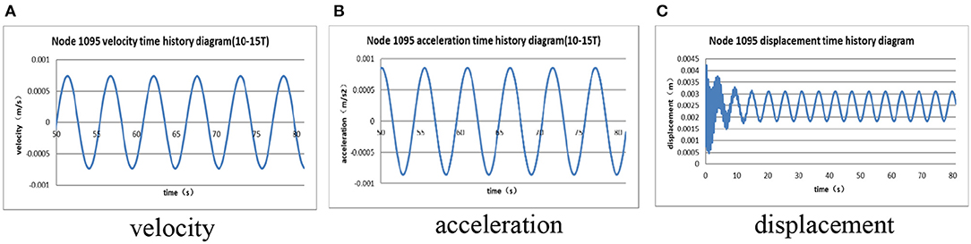
Figure 7. Time histories of dynamic responses under working condition with regular waves. (A) Velocity; (B) acceleration; (C) displacement.
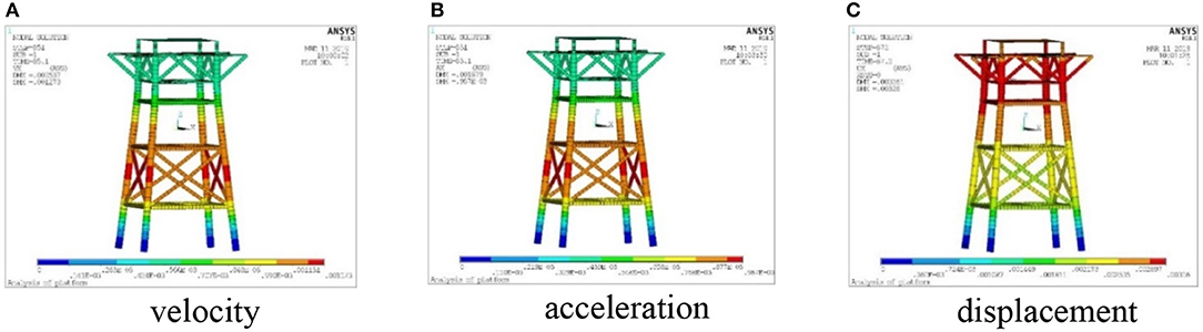
Figure 8. Dynamic response contours under working condition with regular waves. (A) Velocity; (B) acceleration; (C) displacement.
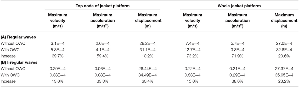
Table 4. Statistics of dynamic responses under working condition.
According to Table 4A, the maximum displacement, velocity, and acceleration of the platform with OWC device are larger than those without OWC device, while the velocity and acceleration increase 60–75%, and the displacement only increases 10–20%. However, the overall dynamic response is still at a very small value level, which is similar with the results of Zhang and Liu (2018).
Under the action of working condition with irregular waves, and the JONSWAP wave spectrum is used, the time histories of dynamic response of the top node of the jacket platform integrated with OWC device (Node No. 1095, shown in Figure 2) are shown in Figure 9. In addition, the contours of maximum structural dynamic responses, including the velocity, acceleration, and displacement are shown in Figure 10. The results of dynamic responses of the jacket platform with and without OWC device are compared in Table 4B.
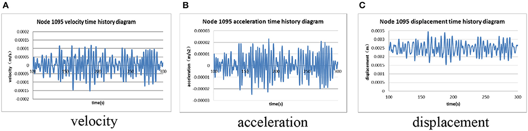
Figure 9. Time histories of dynamic responses of working condition with irregular waves. (A) velocity; (B) acceleration; (C) displacement.
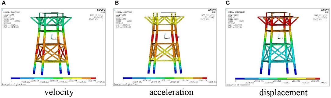
Figure 10. Dynamic response contours under working condition with irregular waves. (A) Velocity; (B) acceleration; (C) displacement.
According to Table 4B, the maximum displacement, velocity, and acceleration of platform with OWC device are larger than those without OWC device, while the velocity increases ~15%, and the acceleration and displacement increase ~30%.
To assess the safety of the jacket platform under extreme condition, the structure parameters of OWC device are kept unchanged, and the dynamic responses are calculated under the extreme condition.
Under the action of extreme condition with regular waves, the results of dynamic responses of the jacket platform with and without OWC device are compared in Table 5A. Under the action of extreme condition with irregular waves, the results of dynamic responses of the jacket platform with and without OWC device are compared in Table 5B.
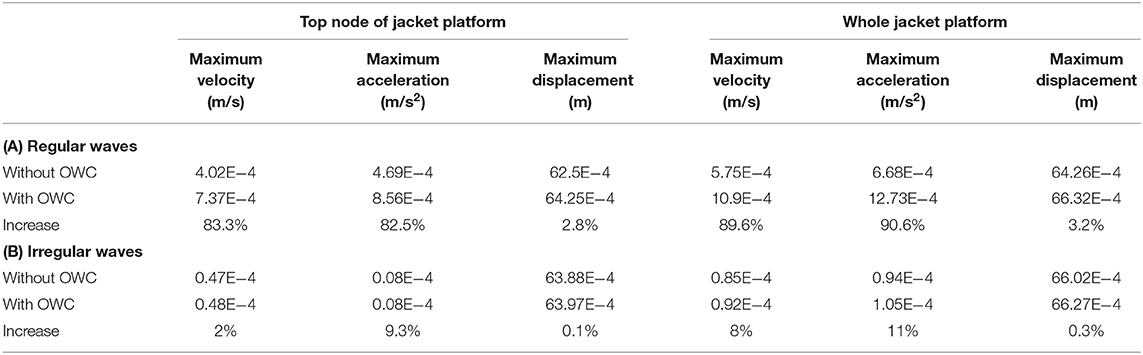
Table 5. Statistics of dynamic responses under extreme condition.
According to Table 5A, the maximum displacement, velocity, and acceleration of platform with OWC device are larger than those without OWC device, while the velocity and acceleration increase 80–90%, and the displacement only increases 3%. According to Table 5B, the maximum displacement, velocity, and acceleration of platform with OWC device are larger than those of without OWC device, while the maximum increment of velocity, acceleration, and displacement is only ~11%. In a word, the effect of OWC device integration into the jacket platform is almost negligible on the dynamic response under extreme condition.
In this paper, based on the design data of a jacket platform working in JZ-20 oil field in Jinzhou, Liaoning province in China, an OWC device integrated into the jacket platform is proposed, the optimal structure parameters of OWC device are determined, and the dynamic responses of platform with and without OWC device are compared under the working and extreme conditions. The main conclusions are obtained as follows:
(1) The wind load accounts about 75 and 89.8% of the total displacement of the jacket platform under working and extreme conditions, respectively, which indicates that the wind load dominates the dynamic responses.
(2) Through given a series of OWC device draft depth and air chamber radius, the optimal structure parameters of the OWC device are solved considering its installation at one certain sea area with the definition of optimization objective function with smallest wave force and highest wave energy capture efficiency.
(3) Compared with the dynamic responses of the top node of the jacket platform and the whole platform under working and extreme conditions with regular and irregular waves, there is very little influence of OWC device integration into the jacket platform on the dynamic responses.
In general, the jacket platform integrated with OWC device can introduce green wave energy while causing almost negligible effects of the dynamic responses. Therefore, the economic benefit of platform oil exploitation can be improved, and it has certain feasibility in the practice application. However, the integrated device may introduce some strength and fatigue problems, which also need to be checked in the future.
The datasets generated for this study are available on request to the corresponding author.
DQ and DN proposed the concept and research framework. CF and CW performed the numerical analysis. HL wrote the manuscript draft. BL provided research advice.
This work was supported by National Key R&D Program of China (Grant nos. 2018YFB1501900, 2016YFE0200100), National Natural Science Foundation of China (Grant no. 51761135011), Shandong Provincial Natural Science Foundation (Grant no. ZR2016EEQ23), and the Fundamental Research Funds for the Central Universities.
CW was employed by the company Offshore Oil Engineering Co. Ltd, Tianjin, China, and BL was employed by the company Sortec Offshore Pte. Ltd, Singapore.
The remaining authors declare that the research was conducted in the absence of any commercial or financial relationships that could be construed as a potential conflict of interest.
Ahmed, E., Gregor, M., and Ning, D. (2018). Hydrodynamic performance of single-chamber and dual-chamber offshore-stationary Oscillating Water Column devices using CFD. Appl. Energy 228, 82–96. doi: 10.1016/j.apenergy.2018.06.069
Ambli, N., Bonke, K., Malmo, O., and Reitan, H. (1982). The Kvaerner multiresonant OWC. Proc. 2nd Int. Symposium Wave Energy Utilisation Trondheim, Norway, 275–295.
Boccotti, P. (2006). Comparison between a U-OWC and a conventional OWC. Ocean Eng. 34, 799–805. doi: 10.1016/j.oceaneng.2006.04.005
Boccotti, P. (2007). Caisson breakwaters embodying an OWC with a small opening-Part I: theory. Ocean Eng. 34, 806–819. doi: 10.1016/j.oceaneng.2006.04.006
Boccotti, P., Filianoti, P., and Fiamma, V. (2007). Caisson breakwaters embodying an OWC with a small opening-Part II: a small-scale field experiment. Ocean Eng. 34, 820–841. doi: 10.1016/j.oceaneng.2006.04.016
Chang, C., Chou, F., Chen, Y., Hsieh, Y., and Chang, C. (2016). Analytical and experimental investigation of hydrodynamic performance and chamber optimization of oscillating water column system. Energy 113, 597–614. doi: 10.1016/j.energy.2016.06.117
Cheng, Y., Dang, Y., and Wu, Y. (2009). Status and trends of the power generation from wave. Appl. Energy Tech. 12:26–30. doi: 10.3969/j.issn.1009-3230.2009.12.008
Dizadji, N., and Sajadian, S. (2011). Modeling and optimization of the chamber of OWC system. Energy 36, 2360–2366. doi: 10.1016/j.energy.2011.01.010
Evans, D. (1976). A theory for wave-power absorption by oscillating bodies. J. Fluid Mech. 77, 1–9. doi: 10.1017/S0022112076001109
Evans, D. (1982). Wave-power absorption by systems of oscillating surface pressure distributions. J. Fluid Mech. 114, 481–490. doi: 10.1017/S0022112082000263
Falcão, A. (2009). Wave energy utilization: a review of the technologies. Renew. Sustain. Energy Rev. 14, 899–918. doi: 10.1016/j.rser.2009.11.003
Gao, R. (2012). Study on Combined Oscillating Floater Buoy Wave Energy Converter. Qingdao: Master thesis, Ocean University of China.
He, F., and Huang, Z. (2014). Hydrodynamic performance of pile-supported OWC-type structures as breakwaters: an experimental study. Ocean Eng. 88, 618–626. doi: 10.1016/j.oceaneng.2014.04.023
He, F., and Huang, Z. (2016). Using an oscillating-water-column structure to reduce wave reflection from a vertical wall. J. Waterway Port Coastal Ocean Eng. 142:04015021. doi: 10.1061/(ASCE)WW.1943-5460.0000320
He, F., and Huang, Z. (2017). Characteristics of orifices for modeling nonlinear power take-off in wave-flume tests of oscillating water column devices. J. Zhejiang Univer. 18, 329–345. doi: 10.1631/jzus.A1600769
He, F., Huang, Z., and Law, A. (2012). Hydrodynamic performance of a rectangular floating breakwater with and without pneumatic chambers: an experimental study. Ocean Eng. 51, 16–27. doi: 10.1016/j.oceaneng.2012.05.008
He, F., Huang, Z., and Law, A. (2013). An experimental study of a floating breakwater with asymmetric pneumatic chambers for wave energy extraction. Appl. Energy 106, 222–231. doi: 10.1016/j.apenergy.2013.01.013
He, F., Leng, J., and Zhao, X. (2017). An experimental investigation into the wave power extraction of a floating box-type breakwater with dual pneumatic chambers. Appl. Ocean Res. 67, 21–30. doi: 10.1016/j.apor.2017.06.009
He, F., Li, M., and Huang, Z. (2016). An experimental study of pile-supported OWC-type breakwaters: energy extraction and vortex-induced energy loss. Energies 9:540. doi: 10.3390/en9070540
He, F., Zhang, H., Zhao, J., Zheng, S., and Iglesias, G. (2019). Hydrodynamic performance of a pile-supported OWC breakwater: an analytical study. Appl. Ocean Res. 88, 326–340. doi: 10.1016/j.apor.2019.03.022
Ji, W. (2017). Thinking on the integrated utilization of wave energy power generation device in oil field. Construct. Design Eng. 4, 123–124. doi: 10.13616/j.cnki.gcjsysj.2017.02.151
Korde, U. A. (1991). On the control of wave energy devices in multi-frequency waves. Appl. Ocean Res. 13, 132–144. doi: 10.1016/S0141-1187(05)80060-4
Liu, W., and Ma, C. (2018). Exploitation and technical progress of marine renewable energy. Adv. Marine Sci. 36, 1–18. doi: 10.3969/j.issn.1671-6647.2018.01.001
Michele, S., and Renzi, E. (2019). A second-order theory for an array of curved wave energy converters in open sea. J. Fluids Struct. 88, 315–330. doi: 10.1016/j.jfluidstructs.2019.05.007
Michele, S., Renzi, E., Perez-Collazo, C., Greaves, D., and Iglesias, G. (2019b). Power extraction in regular and random waves from an OWC in hybrid wind-wave energy systems. Ocean Eng. 191:106519. doi: 10.1016/j.oceaneng.2019.106519
Michele, S., Renzi, E., and Sammarco, P. (2019a). Weakly nonlinear theory for a gate-type curved array in waves. J. Fluid Mech. 869, 238–263. doi: 10.1017/jfm.2019.223
Michele, S., Sammarco, P., and d'Errico, M. (2016). The optimal design of a flap gate array in front of a straight vertical wall: resonance of the natural modes and enhancement of the exciting torque, Ocean Eng. 118, 152–164. doi: 10.1016/j.oceaneng.2016.04.002
Michele, S., Sammarco, P., and d'Errico, M. (2017). Weakly nonlinear theory for oscillating wave surge converters in a channel. J. Fluid Mech. 834, 55–91. doi: 10.1017/jfm.2017.724
Ning, D., Ke, S., Mayon, R., and Zhang, C. (2019). Numerical investigation on hydrodynamic performance of an OWC wave energy device in the stepped bottom. Front. Energy Res. 7:152. doi: 10.3389/fenrg.2019.00152
Ning, D., Wang, R., and Zhang, C. (2017). Numerical simulation of a dual-chamber oscillating water column wave energy converter. Sustainability 9:1599. doi: 10.3390/su9091599
Ning, D., Zhou, Y., and Zhang, C. (2018). Hydrodynamic modeling of a novel dual-chamber OWC wave energy converter. Appl. Ocean Res. 78, 180–191. doi: 10.1016/j.apor.2018.06.016
Perez-Collazo, C., Greaves, D., and Iglesias, G. (2018). A novel hybrid wind wave energy converter for jacket frame substructures. Energies 11:637. doi: 10.3390/en11030637
Qin, H., Wang, Y., and Wang, G. (2013). On caisson breakwater with contracted channel and OWC modeling. Port Waterway Eng. 08, 52–56. doi: 10.3969/j.issn.1002-4972.2013.08.009
Renzi, E., and Dias, F. (2013). Hydrodynamics of the oscillating wave surge converter in the open ocean. Eur. J. Mech. Fluids 41, 1–10. doi: 10.1016/j.euromechflu.2013.01.007
Sarkar, D., Renzi, E., and Dias, F. (2015). Effect of a straight coast on the hydrodynamics and performance of the oscillating wave surge converter. Ocean Eng. 105, 25–32. doi: 10.1016/j.oceaneng.2015.05.025
Scruggs, J. (2009). Harvesting ocean wave energy. Science 323, 1176–1178. doi: 10.1126/science.1168245
Shi, H., and Yang, G. (2010). Design and stability of a new type of caisson breakwater as an OWC wave energy device. J. Ocean Univer. China 40, 142–146. doi: 10.3969/j.issn.1672-5174.2010.09.025
Teixeira, P., Davyt, D., Didier, E., and Ramalhais, R. (2013). Numerical simulation of an oscillating water column device using a code based on Navier-Stokes equations. Energy 61, 513–530. doi: 10.1016/j.energy.2013.08.062
Tidwell, J., and Weir, T. (2006). Renewable Energy Resources (2nd edition). London: Taylor and Francis.
Yu, Z. (1993). The development of ocean wave power generating techniques. Ocean Environ. Eng. 11, 86–93.
Zhang, J., and Liu, H. (2018). Structural response of jacket platform under random wave load. China Offshore Platform 11, 36–42. doi: 10.3969/j.issn.1001-4500.2018.02.007
Zheng, S., Antonini, A., Zhang, Y., Greaves, D., Miles, J., and Iglesias, G. (2019). Wave power extraction from multiple oscillating water columns along a straight coast. J. Fluid Mech. 878, 445–480. doi: 10.1017/jfm.2019.656
Keywords: oscillating water column, jacket platform, wave force, wave energy conversion efficiency, dynamic response
Citation: Qiao D, Feng C, Ning D, Wang C, Liang H and Li B (2020) Dynamic Response Analysis of Jacket Platform Integrated With Oscillating Water Column Device. Front. Energy Res. 8:42. doi: 10.3389/fenrg.2020.00042
Received: 31 December 2019; Accepted: 28 February 2020;
Published: 31 March 2020.
Edited by:
Siming Zheng, University of Plymouth, United KingdomReviewed by:
Fang He, Zhejiang University, ChinaCopyright © 2020 Qiao, Feng, Ning, Wang, Liang and Li. This is an open-access article distributed under the terms of the Creative Commons Attribution License (CC BY). The use, distribution or reproduction in other forums is permitted, provided the original author(s) and the copyright owner(s) are credited and that the original publication in this journal is cited, in accordance with accepted academic practice. No use, distribution or reproduction is permitted which does not comply with these terms.
*Correspondence: Haizhi Liang, bXJfbGlhbmdva0AxNjMuY29t
Disclaimer: All claims expressed in this article are solely those of the authors and do not necessarily represent those of their affiliated organizations, or those of the publisher, the editors and the reviewers. Any product that may be evaluated in this article or claim that may be made by its manufacturer is not guaranteed or endorsed by the publisher.
Research integrity at Frontiers
Learn more about the work of our research integrity team to safeguard the quality of each article we publish.