
95% of researchers rate our articles as excellent or good
Learn more about the work of our research integrity team to safeguard the quality of each article we publish.
Find out more
ORIGINAL RESEARCH article
Front. Energy Res. , 24 January 2020
Sec. Process and Energy Systems Engineering
Volume 8 - 2020 | https://doi.org/10.3389/fenrg.2020.00001
This article is part of the Research Topic Multilevel Converters: Control Techniques for Renewable Energy Resources View all 8 articles
 K. Sasikala*
 R. Krishnakumar
This paper mainly focuses on identifying an optimum controller for Multi Level Inverter Based Switched Mode Power Supply (MLIBSMPS) for constant voltage applications. Generally, there is a greater demand of constant voltage for the sensitive loads. A closed loop control is introduced in the circuit in order to obtain constant voltage quickly if there are any disturbances occur at the input side. In this paper, closed loop Proportional Integral (PI) as well as Proportional Resonant (PR) controlled MLI based SMPS systems are simulated and the comparison of their performance is done. It is seen that an acceptable performance is achieved using PR controlled MLI based SMPS than PI Controlled MLI based SMPS. It also proves that PR Controlled SMPS with 7 level inverters has reduced steady state error and improved time domain response as compared to PI Controlled SMPS.
Switching converters are in greater demand after the evolution of semiconductor technology. Nowadays, Switched Mode Power Supply (SMPS) with greater efficiency can be designed easily with lesser weight and cost effective. SMPS has also become increasingly popular due to its greater efficiency in distributing power to electronic device (Guo et al., 2010). In SMPS, fly back topology is mostly preferred due of its simple design, low cost, and greater efficiency compared to other topologies (Halder, 2014a). This fly back converter is used in applications where the load requires to be separated from mains supply. In addition to the good input/output isolation, the fly back converter uses lesser magnetic and semiconductor components that makes it a perfect converter for low- cost power supply applications (Halder, 2014b; Deepa et al., 2015). This converter steps up as well as steps down the input voltage retaining the similar polarity and ground reference for the input as well as output. MOSFET is used as a switching device whose turn-on and turn-off time is less when compared with other switching devices (Law et al., 2017). Switching devices with higher power handling capacity and switching speeds are readily available in the market. In this paper, fly back converter is cascaded which involves connecting multiple converters in parallel thus operating these converters at a phase shift of 360°/n (n = number of converter modules). Due to cascading, the effective switching frequency can be increased “n” times which in turn high frequency harmonic components can be filtered easily. This cascaded fly back converter reduces the current ripple at both the input as well as output side. The main advantages of cascading are the reduction of cost and size of power filtering components and improved dynamic load performance (Sahu et al., 2016). A 7 level Multi Level Inverter (MLI) is used which is appropriate for high- power and medium voltage operation. In addition to greater power quality, MLI has better electromagnetic interference and lesser switching losses (Dogra and Pal, 2014). This multilevel inverter generates stepped voltage output with the help of numerous dc voltage sources produced by the fly back converter. Practically, it is impossible to expect the load and input voltage to remain constant. Variations in load and input voltages will affect the output voltage which is not desirable (Chandran and Jothi, 2013). To overcome the above drawback, a closed-loop configuration is used wherein a part of the output is fed back to the switch which suitably corrects the duty ratio to maintain the output voltage constant (Sasikala and Krishnakumar, 2019). The PI and PR controllers are used in the feedback path to change the converter duty cycle which in turn the output voltage is regulated (Alzate and Posada, 2017). This works also evaluates the dynamic response and transient behavior of the systems.
Isolated Switched-Mode Power Supply was presented by Reshma et al. A new idea in the design of switched mode energy conversion is given on the account of its intense simplicity, flexibility and performance. It has the capacity to replace a few conventional electric power processing techniques presently in use (Reshma et al., 2016). Multilevel power conversion system was presented by Babaei (2008). It emphasizes the use of multilevel inverters with less number of switches. Various topologies are discussed for utility and drive applications. Based on switching frequency and voltage sustaining capability, the selection of power devices has been investigated (Ebrahimi et al., 2012). Alishah et al. (2015) introduces the multilevel converters for the utility of renewable energy systems. Benefits of multilevel inverters such as improved power quality, simple design, and little switching stress along with the suitability for medium to high power applications are discussed.
MLI is used for power conversion and the reduction of load harmonics. As there is a greater demand in industry, conventional two level- inverter can be replaced with MLI. MLI has gained attention as it has low electromagnetic interference, high efficiency, and low switching frequency applications (Anjali et al., 2018).
A new topology with fewer bidirectional switches and power diodes count is compared against the other topology (Ludois et al., 2010). This paper presents a novel topology for the symmetrical multilevel inverter using a multi-output fly back converter but the bidirectional switches and gate driver circuits' count is very high (Noman et al., 2016; Sangeetha et al., 2016). This topology uses a single DC source which can be from renewable energy sources or energy storage devices (Ajami et al., 2014). The DC input is given to the multiple output fly back converter. The fly back converter's output is fed to the multilevel inverter to produce a seven level output. This structure needs a few switch counts in contrast with the conventional type of MLI (Xiao et al., 2015; Shankar et al., 2017; Lodh et al., 2018).
The modern controller usage in closed loop SMPS is totally fascinating. Various controllers like adaptive controllers, Sliding Mode controllers and Lyapunov based techniques are used for controlling the voltage in typical DC-DC converters (Salimi et al., 2015). In any case, switching power supplies (fly back and push-pull converter) haven't been researched unequivocally utilizing non-linear control draws near.
Likewise in mechanical switch mode power supplies, the change in load and line can be noticed under different operational conditions which lead to instability of the ordinary closed loop controller. Contrasted with other modern controllers, fly back control supply is utilized broadly in applications where low as well as medium power is sufficient (Kalirasu, 2017).
The above papers do not report the use of MLI for Switched Mode Power Supply (SMPS) and also the comparison of Proportional Integral (PI) and Proportional Resonant (PR) controlled SMPS is not dealt with. This work proposes MLI for SMPS and also compares the dynamic behavior of Proportional Integral (PI) and Proportional Resonant (PR) controlled SMPS.
The Basic equation for calculating the output of the fly back converter is given by,
where
Vi = Input Voltage
V0 = Output Voltage
D = duty cycle
N2/N1 = transformer turns ratio
The Number of turns in the transformer is given as
where k = 4.4
q = maximum flux in the core
f = frequency in Hz
V1 and V2 are the RMF values of induced EMF in the primary and secondary winding, respectively.
The peak primary current (ip) is dependent on the input voltage Vi, the primary inductance Lp and the on time of the switch,
The average power delivered to the load,
where
Lp = primary inductance if the transformer
T = switching period
Efficiency of the converter
The PI controller is used in industrial application as it is simple and easy to design and effective. This controller removes all the unwanted oscillations and steady state error. The transfer-function of a PI controller takes the form of
where
K1 = proportional constant
K2 = Integral constant
The model of PR was established from fractional-differentiation. The PR controller introduces an infinite gain at a particular resonant frequency to remove steady state error at that particular frequency. The PR response is better than that of the PI controlled system. The transfer-function of a PR controller takes the form of
The fly back SMPS consists of a diode bridge rectifier with a capacitor filter, high frequency switching device, a fly back transformer followed by the output rectifier and filter. In Figure 1, proposed closed loop MLIBSMPS system is shown where a multilevel inverter is introduced between the rectifier and the fly back converter. The fly back converter is also cascaded to reduce the current ripple at both the input as well as output side. At the output side a cascade filter is introduced which reduces the output current ripple. The fly back SMPS is operated in both voltage control mode (outer loop) as well as current control mode (inner loop). In Figure 1, PI controllers are used for both Voltage control mode as well as current control mode. In Figure 2, PI controllers are replaced with PR controllers and the output voltage, current, and power is measured. Here, the dynamic performance of the both the controllers is compared. In both modes, the output voltage is evaluated with reference yield voltage to provide the error signal. The obtained current signal is again related with reference current to get PWM signal for fly back converter. This error signal is coursed by the PI as well as PR to sustain the output voltage constant and diminish the steady state errors. The main ease of these two control modes are simple design, easy control and good voltage regulation.
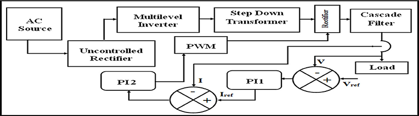
Figure 1. MLIBSMPS block diagram with PI controller in two loop mode.
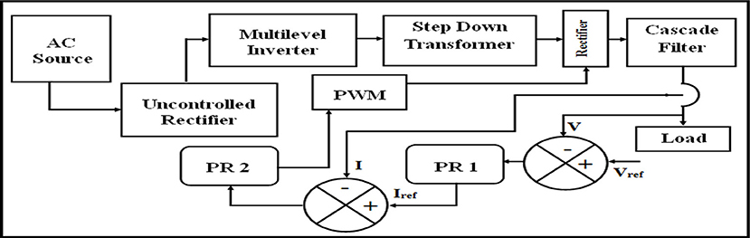
Figure 2. MLIBSMPS block diagram with PR controller in two loop mode.
The results of MLIBSMPS with PI and PR controller in closed loop configurations are discussed simultaneously with the simulation diagram and along with their results.
The simulation diagram of MLIBSMPS circuit with PI Controller (PIC) in two loop mode is shown in Figure 3 and the circuit diagram of 7-level inverter is given in Figure 4. A sine wave input of 250 V is given to the two loop PI controller and a disturbance is created at 0.7 s at the input side which is shown in Figure 5. The voltage across rectifier is obtained as 210 V. Transformer primary and secondary voltage of MLIBSMPS are obtained as 200 and 100 V, respectively, in Figure 6. Voltage across R-load with two loop PIC is shown as 90 V in Figure 7. It is observed that the output voltage reaches its peak at 1.30 s and settles at 1.38 s. Current through R-load with two loop PIC is shown 1.9 A in Figure 8. It is observed that the output current reaches its peak at 1.29 s and settles at 1.39 s.
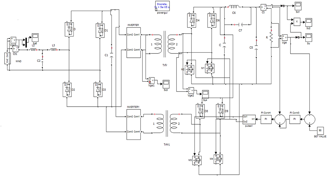
Figure 3. Simulation diagram of MLIBSMPS with PI controller in two loop mode.
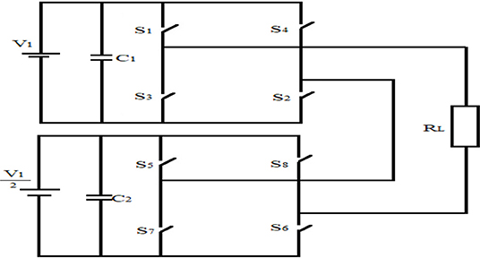
Figure 4. Circuit diagram of 7-level inverter.
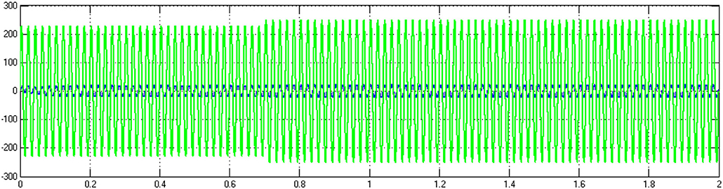
Figure 5. Input voltage of MLIBSMPS.
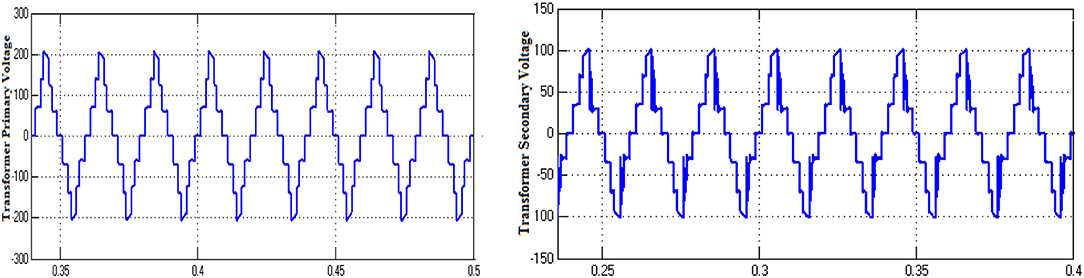
Figure 6. Transformer primary and secondary voltage of MLIBSMPS with PIC.
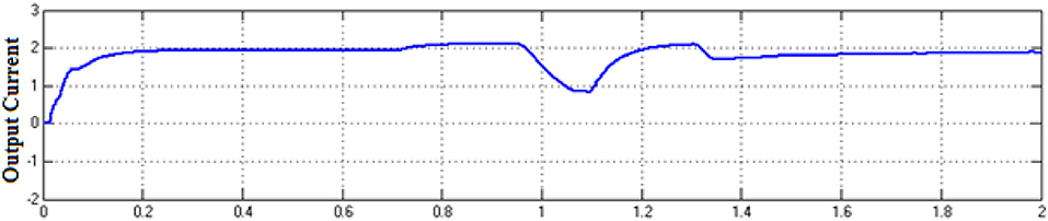
Figure 7. Output voltage of MLIBSMPS with PIC.
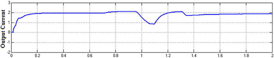
Figure 8. Output current of MLIBSMPS with PIC.
The simulation diagram of MLIBSMPS circuit with PR Controller (PRC) in two loop mode is given in Figure 9. A sine wave input of 250 V is given to the two loop PR controller and a disturbance is created at 0.7 s at the input side. The voltage across rectifier is obtained as 210 V. Transformer primary and secondary voltage of MLIBSMPS are obtained as 200 and 100 V, respectively, which are similar to the one shown in Figure 6. Voltage across R-load with two loop PRC is shown as 90 V in Figure 10. It is observed that the output voltage reaches its peak at 0.84 s and settles at 1.14 s. Current through R-load with two loop PRC is shown 1.9 A in Figure 11. It is observed that the output current reaches its peak at 0.82 s and settles at 1.13 s. The output power with two loop PIC and PRC is shown in Figure 12 and its value is 200 W.
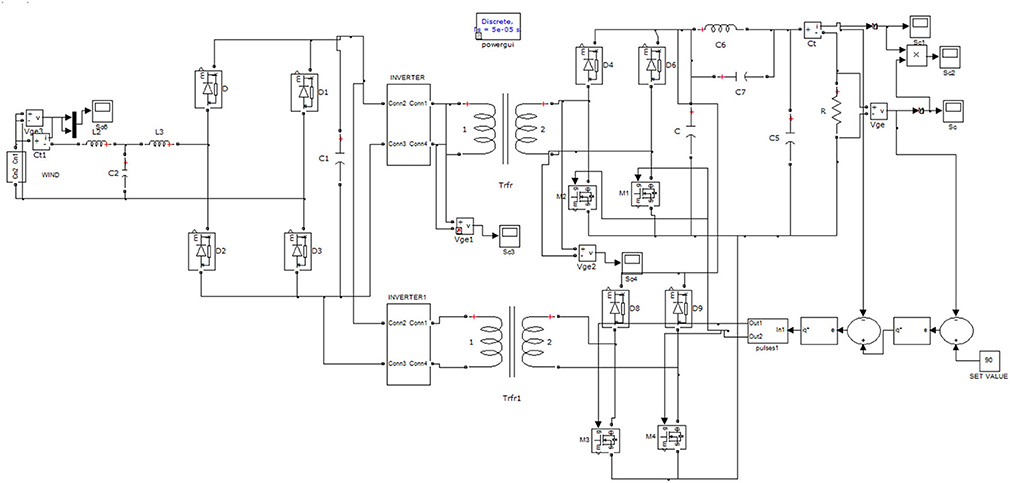
Figure 9. Simulation diagram of MLIBSMPS with PR controller in two loop mode.
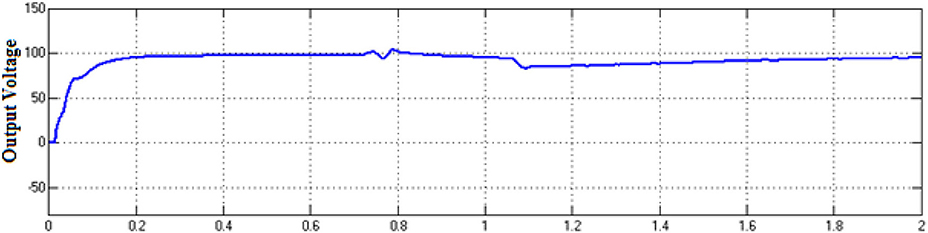
Figure 10. Output voltage of MLIBSMPS with PRC.
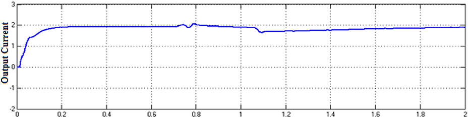
Figure 11. Output current of MLIBSMPS with PRC.
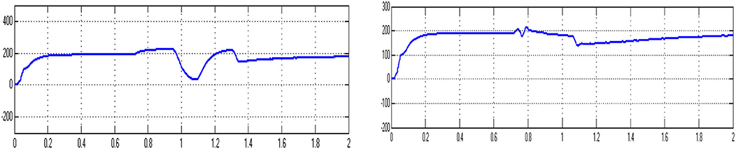
Figure 12. Output power of MLIBSMPS with PIC and Output power of MLIBSMPS with PRC.
The evaluation of time domain parameters (Voltage) with PI and PR controller is given in Table 1. It is observed that with PR controller, there is a reduction of rise-time from 0.76 to 0.74 s, the peak time from 1.30 to 0.84 s, the settling-time from 1.38 to 1.14 s and the steady state error from 1.3 to 0.8 V.

Table 1. Summary of time domain parameters (Voltage) with PIC and PRC.
The evaluation of time domain parameters (Current) with PI and PR controller is given in Table 1. It is observed that with PR controller, there is a reduction of rise- time from 0.77 to 0.75 s, the peak time from 1.29 to 0.82 s, the settling-time from 1.39 to 1.13 s and the steady state error from 0.7 to 0.4 V.
It is observed from Tables 1, 2 that the obtained time domain parameter values in PR controllers are reduced when compared to PI Controllers. Hence, it is proved that the dynamic response of the system is improved in PR Controllers than PI Controllers. The parameter used for PI and PR controllers is shown in Table 3. These values are used in the simulation of PIC and PRC.
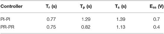
Table 2. Summary of time domain parameters (Current) with PIC and PRC.

Table 3. PI and PR controller parameters.
To demonstrate the practical possibility of the proposed converter, hardware of Cascaded Flyback SMPS (CFSMPS) is fabricated and tested in the laboratory. The hardware of CFSMPS has rectifier, transformer, flyback converter, and control circuit modules. Hardware snapshot is given in Figure 13. The input voltage is given to the Cascaded Flyback SMPS. The Switching pulses for M1 and M2 of fly back converter and the output voltage of 7- level inverter are illustrated in Figure 14. Output voltage and current are shown in Figure 15. List of components used are given in Table 4. The magnitudes of input as well as output are in accordance with the expected results. It is interesting to note that the input current ripple is very low due to cascading techniques. Comparison of Simulation and hardware values of CFSMPS are given in Table 5.
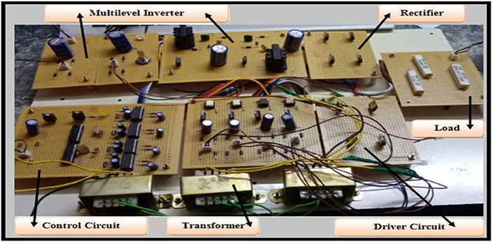
Figure 13. Hardware structure of CFSMPS.
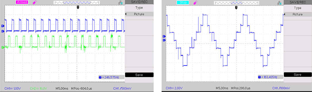
Figure 14. Switching pulses for M1 and M2 of CFSMPS and Output voltage of 7 level inverter.
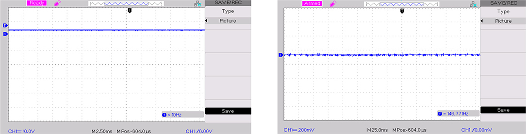
Figure 15. Output voltage and Output current of CFSMPS.
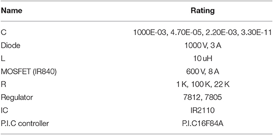
Table 4. List of components used for hardware of CFSMPS.
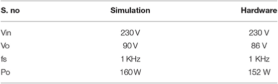
Table 5. Simulation and hardware values of CFSMPS.
Simulation studies were done for Proportional Integral (PI) and Proportional Resonant (PR) controlled closed loop MLIBSMPS. These studies were done using the Simulink-based models. By using controllers, good voltage regulation can be achieved hence efficiency can also be improved. The outcomes signify that the Proportional resonant (PR) controlled closed loop MLIBSMPS gave an improved response as evaluated to the PI controlled closed loop MLIBSMPS. The advantages of the proposed system are very fast settling time and low steady state error. The improvement in dynamic response is because of the use of PR controller. The hardware results match with simulation results. The contribution of the present work is to use MLI for SMPS and PRC to regulate load voltage.
All datasets generated for this study are included in the article/supplementary material.
All authors listed have made a substantial, direct and intellectual contribution to the work, and approved it for publication.
The authors declare that the research was conducted in the absence of any commercial or financial relationships that could be construed as a potential conflict of interest.
Ajami, A., Oskuee, M. R. J., Mokhberdoran, A., and Khosroshahi, M. T. (2014). Advanced cascade multilevel converter with reduction in number of components. J. Electr. Eng. Technol. 9, 127–135. doi: 10.5370/JEET.2014.9.1.127
Alishah, R. S., Nazarpour, D., Hosseini, S. H., and Sabahi, M. (2015). Reduction of power electronic elements in multilevel converter using a new cascade structure. IEEE Trans. Ind. Electron. 62, 256–269. doi: 10.1109/TIE.2014.2331012
Alzate, R. E., and Posada, J. (2017). “Design and implementation of proportional-resonant controller for 3-phase current source inverter in Dspace DS1104,” in IEEE Workshop on Power Electronics and Power Quality Applications (PEPQA) (Bogota).
Anjali, K. R., Padmasuresh, L., and Muthukumar, P. (2018). Genetic algorithm based 15 level multilevel inverter with SHE PWM. Int. J. Eng. Technol. 7, 893–897.
Babaei, E. (2008). A cascade multilevel converter topology with reduced number of switches. IEEE Trans. Power Electron. 23, 2657–2664. doi: 10.1109/TPEL.2008.2005192
Chandran, C. R., and Jothi, T. (2013). PID controller based closed loop analysis of a high efficient flyback converter with an active clamp technique. Int. J. Adv. Trends Comput. Sci. Eng. 2, 118–123.
Deepa, K., Saju, H. M., and VijayaKumar, M. (2015). Soft switched multi output flyback converter with voltage doubler. Int. J. Power Electron. Drive Syst. 6, 396–403. doi: 10.11591/ijpeds.v6.i2.pp396-403
Dogra, A., and Pal, K. (2014). Designing and tuning of PI controller for flyback converter. Int. J. Eng. Trends Technol. 13, 117–122. doi: 10.14445/22315381/IJETT-V13P225
Ebrahimi, J., Babaei, E., and Gharehpetian, G. B. (2012). A new multilevel converter topology with reduced number of power electronic components. IEEE Trans. Ind. Electron. 59, 655–667. doi: 10.1109/TIE.2011.2151813
Guo, S., Lin-Shi, X., Allard, B., Gao, Y., and Ruan, Y. (2010). Digital sliding-mode controller for high-frequency DC/DC SMPS. IEEE Trans. Power Electron. 25, 1120–1123. doi: 10.1109/TPEL.2009.2039356
Halder, T. (2014a). “Continuous conduction mode (CCM) of operations & stability analysis of the flyback SMPS,” in 1st International Conference on Non Conventional Energy (ICONCE 2014), 292–7. doi: 10.1109/ICONCE.2014.6808729
Halder, T. (2014b). “Spacecraft electrical power systems (EPS) using the flyback converters,” in IEEE Proceedings- 1st International Conference on Non Conventional Energy (ICONCE 2014), 52–57. doi: 10.1109/ICONCE.2014.6808681
Kalirasu, A. (2017). A novel single source multiple output converter integrating buck boost and flyback topology for SMPS applications. Int. J. Electr. Eng. Comput. Sci. l8, 733–6. doi: 10.11591/ijeecs.v8.i3.pp733-736
Law, K., Ng, W., and Wong, W. (2017). Flyback cascaded multilevel inverter based SHE PWM control for STATCOM applications. Int. J. Power Electron. Drive Syst. 8, 100–108. doi: 10.11591/ijpeds.v8.i1.pp100-108
Lodh, T., Pragallapati, N., and Agarwal, V. (2018). Novel control scheme for an interleaved flyback converter based solar PV microinverter to achieve high efficiency. IEEE Trans. Ind. Appl. 54, 3473–3482. doi: 10.1109/TIA.2018.2818655
Ludois, D. C., Reed, J. K., and Venkataramanan, G. (2010). Hierarchical control of bridge-of-bridge multilevel power converters. IEEE Trans. Ind. Electron. 57, 2679–2690. doi: 10.1109/TIE.2009.2030205
Noman, A. M., Addoweesh, K. E., and Al-Haddad, K. (2016). “Cascaded multilevel inverter topology with high frequency galvanic-isolation for grid connected PV system,” in IECON 2016 - 42nd Annual Conference of the IEEE Industrial Electronics Society (Florence), 3030–3037. doi: 10.1109/IECON.2016.7793616
Reshma, K. P., Sreenath, R., and Pai, N. (2016). “Design and implementation of an isolated switched-mode power supply for LED application,” in International Conference on Computation of Power, Energy Information and Communication (ICCPEIC). doi: 10.1109/ICCPEIC.2016.7557277
Sahu, T., Sahu, A., and Pradhan, M. K. (2016). A unity power factor multiple isolated output switching mode power supply using AC-DC converter. Int. J. Res. Advent. Technol. 4, 177–184.
Salimi, M., Soltani, J., Zakipour, A., and Abjadi, N. R. (2015). Hyper plane sliding mode control of the DC DC buck/boost converter in continuous and discontinuous conduction modes of operation. IET Power Electron. 8, 1473–1482. doi: 10.1049/iet-pel.2014.0578
Sangeetha, K., Babu, T. S., Sudhakar, N., and Rajasekar, N. (2016). Modeling, analysis and design of efficient maximum power extraction method for solar PV system. Sus. Energy Technol. Assess. 15, 60–70. doi: 10.1016/j.seta.2016.02.002
Sasikala, K., and Krishnakumar, R. (2019). Fractional PID controlled cascaded flyback switched mode power supply with enhanced time domain response. Int. J. Power Electron. Drive Syst. 10, 909–916. doi: 10.11591/ijpeds.v10.i2.pp909-916
Shankar, J. G., Edward, J. B., Kumar, K. S., and Raglend, I. J. (2017). “A 31-level asymmetrical cascaded multilevel inverter with DC-DC flyback converter for photovoltaic system,” in International Conference on High Voltage Engineering and Power Systems (ICHVEPS) (Bali). doi: 10.1109/ICHVEPS.2017.8225957
Keywords: multi level inverter based switched mode power supply (MLIBSMPS), proportional integral controller (PIC), dynamic response, proportional resonant controller (PRC), steady state error
Citation: Sasikala K and Krishnakumar R (2020) An Improved Response of Multi Level Inverter Based PR Controlled SMPS. Front. Energy Res. 8:1. doi: 10.3389/fenrg.2020.00001
Received: 02 December 2019; Accepted: 06 January 2020;
Published: 24 January 2020.
Edited by:
Sudhakar Babu Thanikanti, Universiti Tenaga Nasional, MalaysiaReviewed by:
Suresh Srinivasan, Annamacharya Institute of Technology and Sciences, IndiaCopyright © 2020 Sasikala and Krishnakumar. This is an open-access article distributed under the terms of the Creative Commons Attribution License (CC BY). The use, distribution or reproduction in other forums is permitted, provided the original author(s) and the copyright owner(s) are credited and that the original publication in this journal is cited, in accordance with accepted academic practice. No use, distribution or reproduction is permitted which does not comply with these terms.
*Correspondence: K. Sasikala, c2thbGEuc2VAdmVsc3VuaXYuYWMuaW4=
Disclaimer: All claims expressed in this article are solely those of the authors and do not necessarily represent those of their affiliated organizations, or those of the publisher, the editors and the reviewers. Any product that may be evaluated in this article or claim that may be made by its manufacturer is not guaranteed or endorsed by the publisher.
Research integrity at Frontiers
Learn more about the work of our research integrity team to safeguard the quality of each article we publish.