 Mohammed Ridha Jawad Al-Tameemi
 Youcai Liang
 Zhibin Yu
95% of researchers rate our articles as excellent or good
Learn more about the work of our research integrity team to safeguard the quality of each article we publish.
Find out more
ORIGINAL RESEARCH article
Front. Energy Res. , 19 November 2019
Sec. Process and Energy Systems Engineering
Volume 7 - 2019 | https://doi.org/10.3389/fenrg.2019.00131
This article is part of the Research Topic Organic Rankine Cycle for Efficiency Improvement of Industrial Processes and Urban Systems View all 7 articles
Heating sector is one of the key emitters of greenhouse gases, and thus innovations are needed to improve the energy efficiency of heating technologies. In this paper, a recently proposed gas powered heating system that integrates an Organic Rankine Cycle (ORC) with a heat pump has been further investigated. Two different designs of the combined system were modeled, and their performances were compared and analyzed. In the first design, the cold water is firstly heated in the heat pump condenser and then further heated in the ORC condenser to achieve the required final temperature. In the second design, the water is firstly heated in the ORC condenser and then further heated in the heat pump condenser. The results showed that the first design can achieve better overall fuel-to-heat efficiency. Using Aspen Plus, a dynamic model has then been developed to study the optimal control strategies for this design when ambient conditions change. The results revealed that, for the ambient temperature range of 7–15°C, increasing air mass flow rate is sufficient to maintain the overall system performance. While when ambient temperature is below 7°C, more heat is required from the gas burner that would reduce the fuel-to-heat efficiency.
Heating sector is one of the key emitters of greenhouse gas in countries with cold climate conditions. Taking UK as an example, heating accounts for around 50% of its total energy consumption and contributes to approximately one third of its carbon emissions (UK Government, 2009). Gas boilers are the most common appliances for providing domestic hot water and space heating. Heat pumps are believed to be the key technology for decarbonizing heating sector. Small scale air source heat pumps (ASHP) are attractive for heating at household levels. Although air source heat pumps are relatively mature, they are not installed as widely as expected.
For air source heat pump, the operation parameters and control strategy are still the main focus for performance improvement. Fischer et al. (2017) discussed the effect of different control strategies and boundary conditions on the performance of heat pumps and recommended the trade-off between system complexity and performance. A self-optimizing control scheme was proposed by Hu et al. (2015) to improve the system performance of the air source heat pump by using the extreme seeding control strategy, which is adopted to match the varying in boundary parameters and the operation condition. Gupta and Irving (2013) developed a model responsive to variations in source and sink temperatures and the study showed correct response to changes in ambient temperatures. These researches attempted to use the control strategy to make the system operated at the optimal condition.
There are still several challenges that hinder the wide uptake of air source heat pumps, one of which is their low performance in winter due to the high temperature difference between the evaporation and condensation processes (Villarino et al., 2017). To overcome this challenge, some researchers have proposed a hybrid system. Performance improvement, flexible operation of hybrid systems, and low capital and operating costs are necessary to ensure heating technologies are attractive to end users (He et al., 2017). Li (2018) has proposed a hybrid heating system combining a heat pump with a gas fired water heater. The results showed that the control strategy adopted in the parallel loop hybrid system has the potential to improve the economic benefit by 10–60% when the system operates with the ambient temperature range from −12 to 20°C. While in a further study, Li and Du (2018) proposed an alternative control strategy which could reduce energy cost by 10–23% when the ambient temperature is between 0 to 12°C.
In recent years, more and more attention has been paid to heating technologies that recover waste heat to improve energy efficiency when fossil fuel is used. For instance, it is proposed to use an internal combustion engine to directly drive a vapor compression cycle heat pump, and the waste heat rejected by the engine is recovered to improve the overall energy efficiency. Yang et al. (2013) developed and demonstrated such a system for hot water production applications. Hu et al. (2017) also investigated a similar system for space heating. The engine's exhaust gases were mixed with ambient air as the heat source for the evaporator of the heat pump. Liu et al. (2017, 2018) design and experimentally test a prototype for domestic water application.
Another attractive waste heat recovery system that has been widely investigated in the literature is the Organic Rankine Cycle (ORC). The ORC cycle has the ability to recover low grade waste heat and converted it into useful mechanical power. It also allows the production of high-pressure superheat vapor that can be used to generate electrical and/or thermal energy if designed for cogeneration. Various heat sources can be used for an ORC cycle such as heat from fossil fuel burning, industrial waste heat and solar thermal energy (Dirker et al., 2019). Markides (2015) conducted a study on an ORC cycle for utilizing solar energy from non-concentrated and low concentrated solar collector and aims to produce a power output from 1 kW to 1 MW. The study support that the system performance is highly dependent on the geographic location, diurnal and seasonal variation. For a weather with high cloud coverage like the UK, the author suggested using thermal storage unit with the associated consequence of operating cost. Castelli et al. (2019) carried a thermoeconomic analysis of an ORC cycle design for waste heat recovery from Aluminum production factory. A comparison study of various pure and zeotropic working fluids was also conducted. The results show that a cycle with pure HFE-347mcc has the highest exergy efficiency of around 85%. While for mixed refrigerant, isobutane–isopentane shows high exergy efficiency which can lead increase the net electrical power output by 3.3% compared to pure fluids. From the economic perspective, RE347mcc is the best across the selected range of electricity price. Another optimization study of an ORC cycle was conducted in terms of working fluids, operating conditions, cycle configuration and their effects on turbine performance (White and Sayma, 2019). The results show that for a model with variable expander efficiency, the predicted output power decline with the rise in heat source temperature. The average reduction in power noted in subcritical and transcritical cycle is 13.2 and 11.5% compared to optimal cycle with fixed expander efficiency. In addition, a transcritical cycle can generate 2.1–7.8% more power than subcritical cycle however, subcritical cycle is favorable economically as it has smaller heat exchanger areas.
Zhao et al. (2017) presented a combined heat and power (CHP) system with waste heat recovery. The proposed system used an absorption HP system to reduce the return water temperature for further heat recovery and enhance the overall system thermal efficiency. Furthermore, the new system layout was compared with the traditional gas boiler district heating system, and the results showed that the new technology could reduce the flue gas temperature to 11°C. As a result, the energy consumption is reduced by 6% and the HP has achieved a COP of 25 which can be consider a significant improvement compared with the electrical HP.
Eisavi et al. (2018) carried out energy and exergy analysis on a solar driven combined heat and power system. The objective was to produce mechanical power using an ORC cycle, as well as heating and cooling using a lithium bromide-water absorption refrigeration system. In their absorption HP cycle, double effect absorption chiller was adopted and the results were compared with a similar CHP system having single effect absorption chiller. The results showed that the cooling capacity could be increased by 48.5% when using the double effect absorption chiller instead of the single mode with the same amount of heat consumed.
Our previous work (Liang et al., 2018) has proposed and studied a gas fuelled water heater that integrates an ORC cycle and HP cycle. It consists of a gas burner, an Organic Rankine Cycle (ORC) power generator, and an air source heat pump cycle. In this paper, we will further the thermodynamic analysis to understand the design strategies and operational principles of such integrated energy system. A comprehensive numerical research is carried out to simulate and compare different system configurations in order to identify the best system configuration. Dynamic models using Aspen Plus are then developed to study the control strategies to operate the system when the ambient conditions changes, in order to maintain a stable system performance and keep the heat pump evaporator frost-free.
Essentially, the proposed system consists of a gas burner, a power generation cycle, and a heat pump cycle. The thermal energy generated from combustion of natural gas in the burner is used to drive an ORC and the mechanical power generated is then used to directly drive a vapor compression cycle heat pump. Ambient air stream and the flue gases are mixed to be used as the heat source for the heat pump.
The thermal energy released from the condensers of both cycles is used to heat cold tap water to the required temperature. Thermodynamically speaking, a low condensation temperature is preferred for the ORC power generation cycle to improve it thermal efficiency, and thus to generate more power. In the meantime, the HP cycle also prefers a lower condensation temperature (essentially a low temperature lift between he evaporator and condenser) to improve its COP. Hence, there needs to be a careful trade-off between these two competing requirements. As a result, there are two possible strategies to heat the cold tap water from at 10°C to the required temperature 65°C.
In the first design, as shown in Figure 1A, the cold tap water is firstly heated in the heat pump condenser, and then further heated in the ORC condenser to reach the final required temperature 65°C. In this way, we can keep the condensation temperature of the heat pump cycle as low as possible to improve its COP. However, this will then cause a much higher condensation temperature for the ORC cycle, decreasing its thermal efficiency.
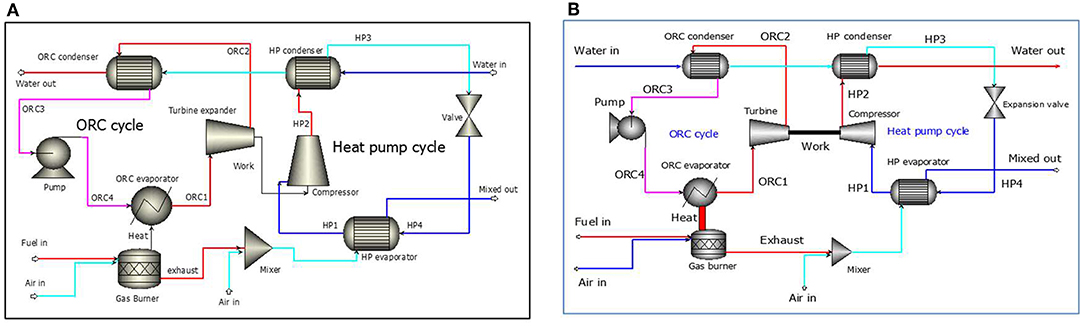
Figure 1. Schematic diagram of two designs. (A) The first design of the combined system. (B) The second design of the combined system.
In the second design, as shown in Figure 1B, the cold tap water is firstly heated in the ORC condenser and then further heated by the heat pump condenser. In this way, we will have a lower condensation temperature for the ORC power cycle, leading to a higher thermal efficiency. However, this design requires the heat pump cycle to operate with a much higher condensation temperature, leading to a lower COP. It is therefore interesting to compare the performance of these different design strategies.
Follow our previous work (Liang et al., 2018), the refrigerant used in ORC was R245fa while R134a was adopted in the HP cycle. The first design as shown in Figure 1A is taken as example to produce the corresponding Temperature—specific entropy (T-s) diagrams for further thermodynamic analysis. Figures 2A,B show the T-s diagram of the ORC and Heat Pump cycles, respectively. For both HP and ORC cycles, each thermodynamic process (evaporation, condensation, compression, and expansion) is denoted by the inlet and outlet refrigerant state. For example, HP1 represents R134a state at HP compressor inlet and HP1-HP2 represents the compression process. While ORC1-ORC2 represents the expansion process in the ORC expander, and so on.
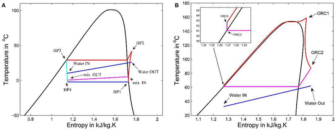
Figure 2. T-s diagrams for two subcycles. (A) T-s diagram for HP cycle (using R134a). (B) T-s diagram for ORC cycle (using R245fa).
An in-house MATLAB code is developed, and the steady state simulations were compared with the results obtained using an ASPEN plus model as a bench mark. In both models, the database REFPROP (Lemmon and McLinden, 2013) was used to provide the thermophysical properties of working fluid. Some assumptions are listed as the following:
• Air consists of 79% nitrogen and 21% oxygen by volume.
• Variable isentropic efficiency correlations of the HP compressor and ORC expander are adopted from the literature (Brandon et al., 2012; Declaye et al., 2013). While a constant isentropic efficiency of 90% is assumed for the liquid pump of the ORC cycle.
• The HP compressor is driven by the ORC expander through a common shaft, and the mechanical losses are neglected.
• Heat loss and pressure losses in all heat exchangers and pipes are neglected.
• ORC is operated under a pressure closed to the critical point of the working fluid (Al-Tameemi et al., 2019).
• A superheat degree of 5°C is assumed at the inlet of the expander of ORC.
• Assume a HP evaporation temperature of 2.5°C and a corresponding pressure of 3.2 bar, which can ensure a minimum pinch point temperature difference of 3°C and maintain evaporator outlet temperature around 5.5°C to avoid frost formation on the evaporator surface (Vocale et al., 2014).
• Pinch point temperature difference is 3°C in both HP and ORC condensers (Ju et al., 2018).
• Cold tap water is heated from 10 to 65°C.
• The output heating capacity of the system is set to be 20 kW.
The energy conservation equation in the burner is:
The heat transfer in the HP evaporator can be calculated as:
The total heat transferred in the HP condenser is calculated as:
The thermal energy generated by the gas burner is used to evaporate R24fa in the ORC evaporator.
The ORC thermal efficiency is defined as the ratio of the net power output (i.e., the difference between the mechanical power produced by expander and the electrical work consumed by the pump) over the total heat absorbed by the ORC evaporator:
The coefficient of performance (COPh) of heat pump cycle is defined as the ratio between the heat rejected by the condenser over the work consumed by the compressor.
The fuel-to-heat efficiency of the integrated system is then defined as:
The total heat released from the gas burner is calculated as:
The heating value of methane is assumed to be 55.5 kJ/kg and combustion efficiency is assumed as 100%.
The required evaporator area is calculated as:
The overall heat transfer coefficient is assumed as a constant value of U = 0.85 kW/m2·°C, and constant correction factor of F = 1. ΔT1 represents the temperature difference between the hot and cold streams at the evaporator outlet. While ΔT2 refers to the temperature difference of the hot and cold streams on the evaporator inlet.
In addition to the steady models, a dynamic model has also been developed using Aspen Plus to investigate the control strategy for operating the system when the ambient temperature varies. For simplification, only dynamic conservation equation for mass for working fluid is adopted in this model. The linear form of the mass balance equation:
The partial differential form of Equation (9) is:
Equation (10) can be simplified to Ordinary Differential Equations (Chen and Yu, 2018):
This equation can be applied for both evaporator and expansion valve.
Where
, controller output (refrigerant mass flow kg/s)
ubias, refrigerant mass flow at steady state
kc, controller gain (it is set to 5 for this case)
E(t), controller error (it is equal to set point—process variable)
TI, controller reset time (it is set to 20 s for this case)
TD, controller derivative time (it is set to 1 min for this case).
The optimization procedure for the combined system has been carried out for the first design. It is widely cited in the literature that reducing the pinch point temperature difference (PPTD) across a heat exchanger can improve cycle efficiency performance. The PPTD approach has been adopted to optimize heat transfer across cycles' heat exchangers during the simulation process.
In this research, a minimum PPTD of 3°C across HP condenser and evaporator as well as ORC condenser, while the minimum PPTD for the ORC evaporator is set to 30°C. Furthermore, water temperature at the HP condenser outlet has been adjusted to identify the optimal value.
Figure 3 shows the variation in the work of the HP compressor and COPh due to the changes in the water temperature leaving the first heating stage (i.e., HP condenser). The condensation pressure increases as Tw−exit−HP increases, leading to steady increase in the compressor work which consequently reduces the heating coefficient of performance of the HP cycle (COPh).
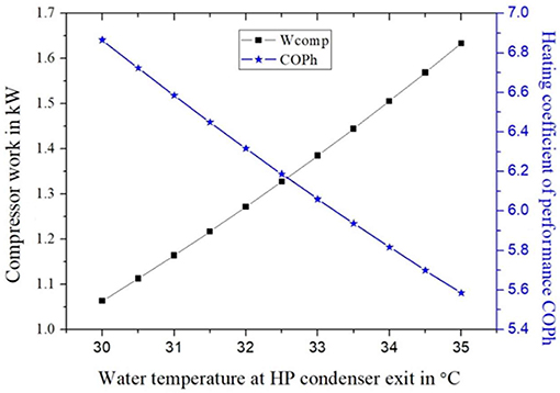
Figure 3. HP compressor work and COPh under variable Tw−exit−HP.
Figure 4 shows the variation of working fluid mass flow rate in both cycles when changing the water temperature at the exit of the HP condenser. The results show that the R134a mass flow rate increases linearly. This can be attributed to the increase of the Tw−exit−HP and the enthalpies at both the HP condenser inlet (hHP2) and outlet (hHP3), as shown in Equation (3). Meanwhile, the condensation pressure of ORC needs to be increased to maintain the minimum pinch point across it, as a result, the mass flow rate of R245fa increases rapidly. It is worth noting that, due to the direct coupling between the HP compressor and ORC expander, the expander power production will always be the same as work demand of the HP cycle. This imposes an extra boundary condition for the modeling of the overall system.
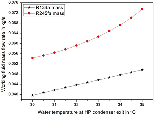
Figure 4. The R134a and R245fa mass flow rates increase when Tw−exit−HP increases.
The effects of the water temperature Tw−exit−HP on the ORC condenser pressure and thermal efficiency are shown in Figure 5. It can be noticed that higher ORC condenser pressure is required to maintain the minimum pinch point temperature as the water temperature entering the ORC condenser increases. The thermal efficiency of ORC is defined as the net power output divided by the heat energy input. As the condensation pressure is higher, the enthalpy difference between the expander inlet and outlet becomes smaller, the working fluid per unit absorbs less energy during the evaporation process although the power output is also decreases. In that case, the outlet temperature of the exhaust gas becomes higher for a fixed PPTD. In other way, less energy will be recycled by the ORC. However, for a given evaporation temperature, the enthalpy drop across the expander become smaller, but the average temperature across the expander becomes higher. Therefore, the increase in the ORC condensation pressure under constant evaporation pressure will enhance the ORC thermal efficiency.
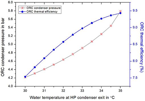
Figure 5. The effect of Tw−exit−HP on the ORC condenser pressure and thermal efficiency.
As shown in Figure 6, the total heat added to water and hence the final water temperature at the outlet of ORC condenser are expected to increase, because both condenser pressure and mass flow for both cycles increase with the increase in the Tw−exit−HP as shown in Figures 4, 5.
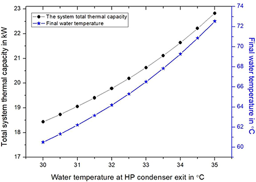
Figure 6. Total system heating capacity and final water temperature under when Tw−exit−HP varies.
Figure 7 shows the variations in the fuel-to-heat efficiency and methane mass flow rate when Tw−exit−HP varies. The fuel-to-heat efficiency is the ratio of total thermal energy absorbed by water in both HP and ORC condensers to the total heat released from the combustion of methane. The fuel-to-heat efficiency increases initially, reaching the highest value of around 135% when the water temperature at HP condenser exit is around 31.5°C. It then declines gradually to reach 131.8% at a temperature of 35°C. With the initial rise in the water temperature, there is linear increase in both ORC thermal efficiency and R245fa mass flow as shown in Figures 4, 5. However, when the Tw−exit−HP is above around 32°C, the rate of increment in the ORC efficiency declines with an opposite trend noted in the ORC mass flow. The increment in the ORC mass flow will require higher methane mass flow rate to evaporate the working fluid. This consequentially reduces the fuel-to-heat efficiency.
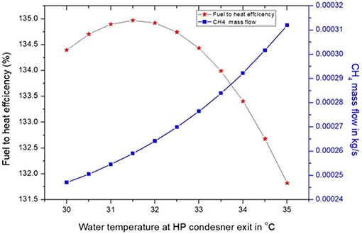
Figure 7. Fuel-to-heat efficiency and CH4 mass flow rate when Tw−exit−HP varies.
The optimum performance at the state steady conditions from the above optimization procedure has been compared with an ASPEN PLUS model. The details of the comparison are shown in Tables 1, 2. The results are obtained when the system present a highest fuel-to-heat efficiency, which demonstrate a good agreement between these two models, so that we use the present model to further investigate the proposed system.
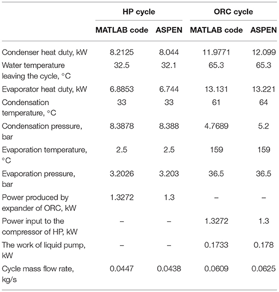
Table 1. Combined cycle parameters by ASPEN and MATLAB code.
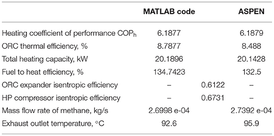
Table 2. Cycle efficiency and gas burner design parameters.
In this approach, the water is heated by ORC-Condenser and HP-condenser in series as shown in Figure 1B. Generally, the modeling procedure and assumptions are the same as the previous model. In addition, the condenser pressure for both cycles are iterated until the water temperature at HP cycle outlet reaches the required value. Furthermore, the ORC mass flow rate is increased gradually until the total heating capacity of the combined cycle is equal to 20 kW. A summary of simulation results for approach two is presented in Tables 3, 4.
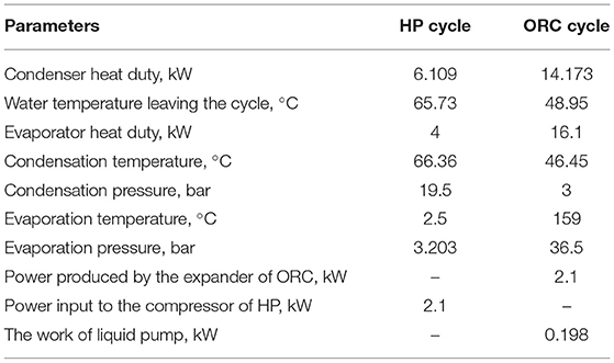
Table 3. Steady state result for the second approach.
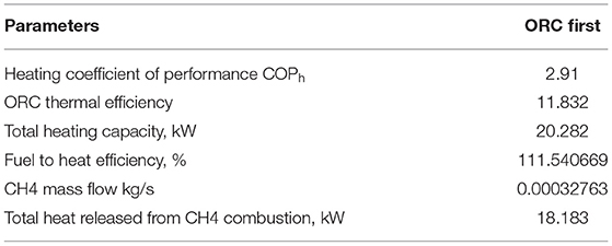
Table 4. Combined cycle performance for second layout.
From the above results, both layouts can produce the required thermal energy of 20 kW to heat water from 10 to 65°C. Although both approaches have achieved nearly equal overall heating duties, the first layout has higher overall fuel-to-heat efficiency (135%) than the second design (111%). This is because the HP heating coefficient of performance has declined by 47% despite the increase in the ORC efficiency by 21% achieved in the second approach. Furthermore, more methane is required in the second approach to achieve required thermal energy in the ORC evaporator.
Over the course of the year, the ambient air temperature varies considerably. For instance, the average air temperature in the UK ranges between 5 and 15°C but would drop to below zero in some winter days. Variation in ambient temperature is one of the main factors that affect the performance of air-sourced heat pump system. It is therefore essential to investigate control strategies that can tackle such variation. In this section, the first design has been used as example to develop the required control strategies to operate the system when ambient conditions change.
To improve heat extraction when air temperature declines, the air mass flow of ambient is adjusted accordingly. However, this strategy is only sufficient for certain temperature range. In this approach, the air mass flow rate is initially iterated under constant HP evaporator areas which is calculated using Equation (8). Other design parameters were obtained from Tables 1–3.
A dynamic model has been developed by using ASPEN PLUS. Figure 8 shows the schematic diagram of the dynamic model for control strategy one. PID controller (B1) locates between the mixer inlet and evaporator outlet. The PID controller output (OP) is the ambient air mass flow rate in kg/s, while process variable (PV) is the temperature of the mixture leaving the evaporator. The set point (ST) is constant at 5.5°C to avoid frost formation on the evaporator. The tuning parameters for the PID controller are set as controller gain of 1% and the integral time at 5 min under reverse control action. This setting can ensure gradual distribution of the ambient temperature over a half day course with the highest temperature assumed to occur at mid-day as shown in Figure 9A.
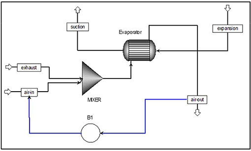
Figure 8. Schematic diagram of the dynamic model for control strategy one.
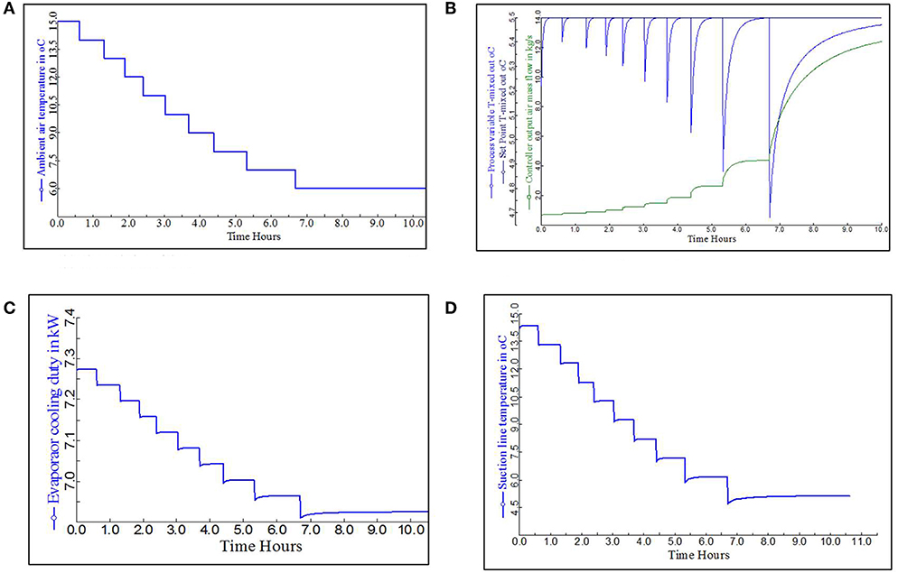
Figure 9. Variation of different operation parameters. (A) The variation of the ambient air temperature over the time lapse. (B) PID controller performance for ambient temperature range 6-15°C. (C) The variation in evaporator cooling capacity over the time lapse. (D) The variation in suction line temperature over the time lapse.
Figure 9B shows the PID performance when ambient air temperature varies from 6 to 15°C. It shows that the controller has maintained the evaporator outlet temperature at 5.5°C (black straight line) by adjusting air mass flow rate (green curve). As the air temperature drops, the controller has increased air mass flow rate to absorb more heat for the heat pump evaporator. However, when the ambient air temperature approaches 6°C, air mass flow rate increases significantly to ~12 kg/s and the evaporator outlet temperature drops slightly to below 5.5°C.
Figure 9C shows the effect of varying air mass flow rate on the HP evaporator duty. As the air mass increases from 0.7 to 11 kg/s, the heat duty of evaporator declines to below 7 kW. Further increase in air mass flow rate has a minor effect on this parameter, which remains nearly constant at 6.8 kW.
Similar results have been shown in the literature Chen and Yu (2018) for an air source heat pump water heater. The dynamic modeling results reveal that increasing air velocity of the evaporator unit always enhances the overall cycle performance. However, this advantage is reduced as the air velocity exceeds 3 m/s.
The heat pump condenser heating duty declines in a similar manner to the evaporator thermal duty. This is because HP condenser heating duty is the sum of HP evaporator thermal duty and the compressor power consumption which is assumed to be constant. Likewise, the superheat degree of the refrigerant at the evaporator exit declines gradually as air mass flow increases. Figure 9D shows the changes in R134a temperature in the suction line when ambient air temperature varies. As the air temperature drops toward 6°C, the refrigerant temperature declines from 15°C to below 7°C.
As shown in the above results, when air temperature drops to 6°C, thermal energy available in the ambient air is insufficient even when the mass flow increased. Thus, another control strategy is proposed when air temperature drops to 6°C or even lower temperature. In this strategy, the mixture of ambient air stream and flue gas is suspended and the gas burner flue gas stream is used as the only heat source for the evaporator.
In this model, the PID controller locates between the methane stream and evaporator outlet stream to maintained constant outlet temperature of 5.5°C by adjusting methane mass flow rate. The schematic diagram of this model is shown in Figure 10.
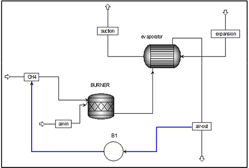
Figure 10. Schematic diagram of the dynamic model for control strategy two.
Figure 11A shows the PID controller performance for the second control strategy. With the drop in ambient air temperature (Figure 11B), the PID controller responds to these changes by increasing the CH4 mass flow rate (OP) to maintain evaporator outlet temperature (PV) close to the 5.5°C (ST). The corresponding changes in exhaust temperature when ambient temperature and methane mass flow changes over time are shown in Figure 11C.
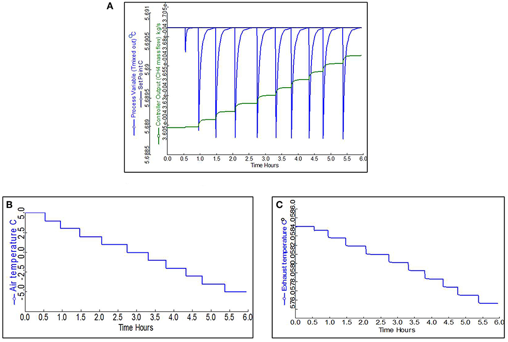
Figure 11. Operating parameters in response to the changing ambient temperature. (A) 15 PID controller performance for ambient temperature range −5 to 5°C. (B) The variation of the ambient air temperature over the time lapse. (C) The variation in burner exhaust temperature over the time lapse.
In this paper, we furthered the thermodynamic analysis of thermally powered heat pump system that integrates an ORC power cycle with a heat pump cycle. In this concept, cold tap water is heated by both the condensers of the ORC power cycle and the heat pump cycle. Two different designs have been modeled and analyzed to identify the best system configuration. In the first design, the cold water was firstly heated by the condenser of heat pump cycle, and then further heated by the condenser of the ORC power cycle. As such, the heat pump can achieve a higher COP, but the ORC power cycle will have a lower thermal efficiency. In the second design, the cold water is firstly heated by the condenser of the ORC power cycle, and then further heated by the condenser of the heat pump cycle. As such, the ORC power cycle can achieve higher thermal efficiency, but the heat pump COP is much lower. The comparison indicates that the first design has much better overall fuel-to-heat efficiency, showing that the performance of the heat pump has stronger impact on the overall system performance.
Based on the first design, dynamic models have then been developed using Aspen plus to investigate the control strategies for operating the integrated system when the ambient conditions vary, in order to achieve the optimal energy efficiency and maintain the HP evaporator frost free in the meantime. The results show that, as ambient temperature drops from 15 to 7°C, increasing air mass flow rate to the HP evaporator is enough to maintain ensure the combined system to produce the required heat at the require temperature. When ambient temperature drops to below 7°C, the extraction of thermal energy from ambient air will be insufficient to provide the required thermal load for the heat pump evaporator despite increasing the mass flow rate of ambient air flow. Under this condition, in order to avoid frost formation in the HP evaporator, the ambient air stream needs to be switched off, and the heat production by the gas burner needs to be increased to provide the required heat production.
The process of construction the experimental rig is already in progress. After that, the experimental results will be used to validate the concept of integration of ORC and heat pump and modify model. The performance of such a combined thermodynamic cycles will be evaluated and compared with the conventional heat pump.
All datasets generated for this study are included in the article/supplementary material.
MA-T contributes to the whole paper writing and modeling. YL contributes to the modeling and proof reading. ZY is the director of the whole paper and he also contributes to the planning of the whole paper and the proof reading.
This research was supported by EPSRC (EP/N020472/1, EP/R003122/1, and EP/N005228/1).
The authors declare that the research was conducted in the absence of any commercial or financial relationships that could be construed as a potential conflict of interest.
MA-T acknowledges the support of his sponsor (University of Diyala/Iraqi Ministry of Higher Education and Scientific Research sponsorship no. 1214) and the University of Glasgow.
Al-Tameemi, M., Liang, Y., and Yu, Z. (2019). Combined ORC-HP thermodynamic cycles for DC cooling and waste heat recovery for central heating. Energy Proc. 158, 2046–2205. doi: 10.1016/j.egypro.2019.01.471
Brandon, J. W., James, B., Groll, E. A., and Horton, T. W. (2012). Experimental Testing of an Organic Rankine Cycle with Scroll-type Expander. Publications of the Ray W. Herrick Laboratories. Paper 52. Available online at: https://docs.lib.purdue.edu/cgi/viewcontent.cgi?article=1052&context=herrick
Castelli, A. F., Elsido, C., Scaccabarozzi, R., Nord, L. O., and Martelli, E. (2019) Optimization of organic rankine cycles for waste heat recovery from aluminum production plants. Front. Energy Res. 7:44. doi: 10.3389/fenrg.2019.00044.
Chen, J., and Yu, J. (2018). Dynamic simulation of an air-source heat pump water heater using novel modified evaporator model. Appl. Thermal Eng. 144, 469–478. doi: 10.1016/j.applthermaleng.2018.08.085
Declaye, S., Quoilin, S., Ludovic, G., and Lemort, V. (2013). Experimental study on an open-drive scroll expander integrated into an ORC (Organic Rankine Cycle) system with R245fa as working fluid. Energy 55, 173–183. doi: 10.1016/j.energy.2013.04.003
Dirker, J., Juggurnath, D., Kaya, A., Osowade, E. A., Simpson, M., Lecompte, S., et al. (2019) Thermal energy processes in direct steam generation solar systems: boiling, condensation and energy storage – a review. Front. Energy Res. 6:147. doi: 10.3389/fenrg.2018.00147.
Eisavi, B., Khalilarya, S., Chitsaz, A., and Rosen, M. A. (2018). Thermodynamic analysis of a novel combined cooling, heating and power system driven by solar energy. Appl. Thermal Eng. 129, 1219–1229. doi: 10.1016/j.applthermaleng.2017.10.132
Fischer, D, Bernhardt, J., Madani, H., and Wittwer, C. (2017). Comparison of control approaches for variable speed air source heat pumps considering time variable electricity prices and PV. Appl. Energy 204, 93–105. doi: 10.1016/j.apenergy.2017.06.110
Gupta, R., and Irving, R. (2013). Development and application of a domestic heat pump model for estimating CO2 emissions reductions from domestic space heating, hot water and potential cooling demand in the future. Energy Build. 60, 60–74. doi: 10.1016/j.enbuild.2012.12.037
He, Y., Wang, R., Roskilly, A. P., and Li, P. (2017). Efficient use of waste heat and solar energy: technologies of cooling, heating, power generation and heat transfer. Front. Energy 11, 411–413. doi: 10.1007/s11708-017-0525-z
Hu, B., Li, C., Yin, X., Cao, F., and Shu, P. (2017). Thermal modeling and experimental research of a gas engine-driven heat pump in variable condition. Appl. Thermal Eng. 123, 1504–1513. doi: 10.1016/j.applthermaleng.2017.05.189
Hu, B., Li, Y., and Cao, F., and Xing, Z. (2015). Extremum seeking control of COP optimization for air-source transcritical CO2 heat pump water heater system. Appl. Energy 1, 361–372. doi: 10.1016/j.apenergy.2015.03.010
Ju, F., Fan, X., Chen, Y., Ouyang, H., Kuang, A., Ma, S., and Wang, F. (2018). Experiment and simulation study on performances of heat pump water heater using blend of R744/R290. Energy Build. 169, 148–156. doi: 10.1016/j.enbuild.2018.03.063
Lemmon, E. W. H., and McLinden, M. O. (2013). NIST Standard Reference Database 23: Reference Fluid Thermodynamic and Transport Properties-REFPROP, Version 9.1. Gaithersburg: National Institute of Standards and Technology, Standard Reference Data Program.
Li, G. (2018). Parallel loop configuration for hybrid heat pump - gas fired water heater system with smart control strategy. Appl. Thermal Eng. 138, 807–818. doi: 10.1016/j.applthermaleng.2018.04.087
Li, G., and Du, Y. (2018). Performance investigation and economic benefits of new control strategies for heat pump-gas fired water heater hybrid system. Appl. Energy 232, 101–118. doi: 10.1016/j.apenergy.2018.09.065
Liang, Y., Al-Tameemi, M., and Yu, Z. (2018). Investigation of a gas-fuelled water heater based on combined power and heat pump cycles. Appl. Energy 212, 1476–1488. doi: 10.1016/j.apenergy.2017.12.117
Liu, F., Tian, Z.-Y., Dong, F.-J., Yan, C., and Zhang, R., and Yan, A.-B. (2017). Experimental study on the performance of a gas engine heat pump for heating and domestic hot water. Energy Build. 152, 273–278. doi: 10.1016/j.enbuild.2017.07.051
Liu, F., Tian, Z-Y., Dong, F-J., Cao, G-Z., Zhang, R., and Yan, A-B. (2018). Experimental investigation of a gas engine-driven heat pump system for cooling and heating operation. Int. J. Refrig. 86, 196–202. doi: 10.1016/j.ijrefrig.2017.10.034
Markides, C. N. (2015). Low-concentration solar-power systems based on organic rankine cycles for distributed-scale applications: overview and further developments. Front. Energy Res. 3:47. doi: 10.3389/fenrg.2015.00047
UK Government. (2009). The UK Low Carbon Transition Plan. Available online at: https://www.gov.uk/government/publications/the-uk-low-carbon-transition-plan-national-strategy-for-climate-and-energy
Villarino, J. I., Villarino, A., and Fernández, F. A. (2017). Experimental and modelling analysis of an office building HVAC system based in a ground-coupled heat pump and radiant floor. Appl. Energy 190, 1020–1028. doi: 10.1016/j.apenergy.2016.12.152
Vocale, P., Morini, J. L., and Spiga, M. (2014). Influence of outdoor air conditions on the air source heat pumps performance. Energy Proc. 45, 653–662. doi: 10.1016/j.egypro.2014.01.070
White, M. T., and Sayma, A. I. (2019) Simultaneous cycle optimization fluid selection for orc systems accounting for the effect of the operating conditions on turbine efficiency. Front. Energy Res. 7:50. doi: 10.3389/fenrg.2019.00050
Yang, Z., Wang, W-B., and Wu, X. (2013). Thermal modeling and operating tests for a gas-engine driven heat pump working as a water heater in winter. Energy Build. 58, 219–226. doi: 10.1016/j.enbuild.2012.10.049
Keywords: heat pump, Organic Rankine Cycle, combined cycles, control strategy, dynamic modeling
Citation: Al-Tameemi MRJ, Liang Y and Yu Z (2019) Design Strategies and Control Methods for a Thermally Driven Heat Pump System Based on Combined Cycles. Front. Energy Res. 7:131. doi: 10.3389/fenrg.2019.00131
Received: 19 July 2019; Accepted: 04 November 2019;
Published: 19 November 2019.
Edited by:
Yiji Lu, Zhejiang University, ChinaReviewed by:
Liang Li, University of Hertfordshire, United KingdomCopyright © 2019 Al-Tameemi, Liang and Yu. This is an open-access article distributed under the terms of the Creative Commons Attribution License (CC BY). The use, distribution or reproduction in other forums is permitted, provided the original author(s) and the copyright owner(s) are credited and that the original publication in this journal is cited, in accordance with accepted academic practice. No use, distribution or reproduction is permitted which does not comply with these terms.
*Correspondence: Zhibin Yu, emhpYmluLnl1QGdsYXNnb3cuYWMudWs=
Disclaimer: All claims expressed in this article are solely those of the authors and do not necessarily represent those of their affiliated organizations, or those of the publisher, the editors and the reviewers. Any product that may be evaluated in this article or claim that may be made by its manufacturer is not guaranteed or endorsed by the publisher.
Research integrity at Frontiers
Learn more about the work of our research integrity team to safeguard the quality of each article we publish.