 Chao Zhang1,2,3,4
 Shuo Huang
95% of researchers rate our articles as excellent or good
Learn more about the work of our research integrity team to safeguard the quality of each article we publish.
Find out more
ORIGINAL RESEARCH article
Front. Energy Res. , 29 October 2019
Sec. Sustainable Energy Systems
Volume 7 - 2019 | https://doi.org/10.3389/fenrg.2019.00120
This article is part of the Research Topic Advances and Challenges in Ocean Wave Energy Harvesting View all 8 articles
This paper presents a modified wave energy device. The wave energy device retains the primitive capture shape of the famous Edinburgh Duck, but uses a new underwater stabilized substrate. The hydrodynamic calculation with frequency-domain models was performed to find out the optimum wave period for the wave energy converter. The results in this paper were obtained by using the Boundary Element Method (BEM). The characteristic function expands of velocity potential in the cylindrical coordinate system was applied to limit computational domain and improve computational speed. The hydrodynamic performance of the device was assessed. The influence of hydraulic damping coefficient was evaluated. Focus was given to the capture width ratio, motion of the device and optimal hydraulic damping coefficient. After 2 years of construction in the shipyard, the device was constructed and an open sea test had been finished near WanShan Island, South China Sea. During the test, the daily power generation and power curve of the device were measured.
In the current energy revolution, renewable energy is playing an increasingly important role. As a significant source of renewable energy, wave energy has the advantages of wide distribution and long persistence and will be an integral part of the future energy supply. Research on wave energy extraction have been carried out in most countries from many years ago, such as USA, China, Australia, UK, Norway, and Japan. Thousands of patents had been granted on how to absorb wave energy and convert it to electricity or other forms of energy (Bergdahl, 1992; Fredrikson, 1992; Nielsen and Meyer, 1998; Gadonneix et al., 2009; Sheng et al., 2017). The most famous of these is the Edinburgh Duck wave energy converter (Salter, 1974) as showed in Figure 1. According to the principle of capturing wave energy, the Edinburgh Duck device belongs to Oscillating Bodies (OB), which captures the wave energy relying on relative motion of different structures.
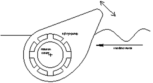
Figure 1. Edinburgh Duck profile with spline-pump power-take-off.
The original plan of the University of Edinburgh was to build an Edinburgh Duck wave-farm as showed in Figure 2. Many Edinburgh Duck devices are arranged in one line across the prevailing wave direction and energy would be captured from their movements relative to a common cylindrical “spine.” Then control technology for Duck wave-farm had been widely studied. The early work was focused on the development of “reactive” control techniques with power capture efficiency of over 80% and had been demonstrated across a wide range of wave periods in wave tank tests of one hundredth scale models (Salter, 1980). Later, a form of “complex conjugate” control techniques was experimental implemented and further improve productivity (Salter et al., 1976). Unfortunately, the plan was eventually shelved for costly offshore construction. Since then, the Solo Duck device began to receive widespread attention.
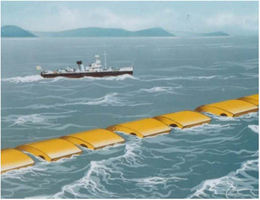
Figure 2. An Edinburgh Duck wave-farm.
During the nineteen-eighties, a float-alone 2 MW Solo Duck as showed in Figure 3 was studied (Skyner, 1987; Salter, 1989; Nebel, 1992). It presented a possible route to the kind of experience in design, construction and operation of sea-going systems. In contrast to the slack-moored Duck-string, the Solo Duck device would be connected with seabed attachments by a tension-leg arrangement that would also provide reaction forces for its power-take-off system. In this particular arrangement, the arm and the lower lines provide torque reaction for the Duck power-take-off system whilst the boxes in the upper lines contain hydraulic mechanisms for yielding and elasticity control (Salter, 1989). However, tank experiments subsequently showed that in steep waves its tension-leg cables would at times go completely slack, and then violently tight again when the hydrodynamic loads reversed again. The tension-leg cables were therefore replaced by post-tensioned concrete tubes (Salter et al., 2007). Compared with the unavoidable stress-reversals of the steel cables within the tension leg system, the steel bars within the concrete tubes would remain always in tension and would therefore be protected against fatigue. However, the design of the concrete pipe in offshore construction has encountered difficulties and risks. It not only increases the cost, but also not conducive to transfer the device when necessary.
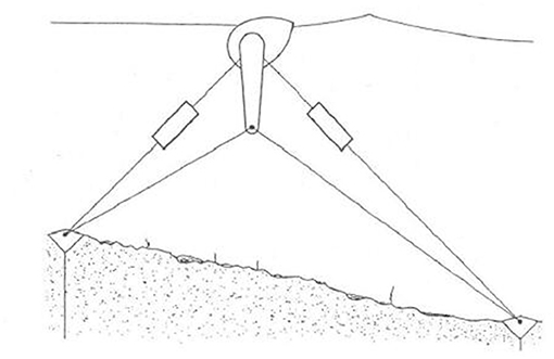
Figure 3. A Solo Duck.
Based on previous studies, a modified wave energy device is proposed in this paper. The characteristics of the device is that it adopts a new type of underwater-stabilized substrate as showed in Figure 4.
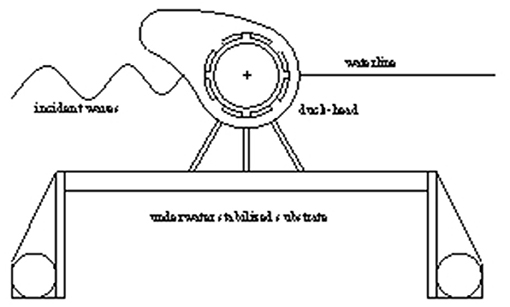
Figure 4. The modified Duck device in working condition.
Underwater stabilized substrate has the following advantages: From the engineering perspective, the design of underwater stabilized substrate improves the convenience of construction and delivery. When a typhoon or other thrilling sea condition occurs, the device can take back the anchor like a ship and transfer in time to ensure safety. In the process of transportation, the stabilized substrate can be folded to save space as showed in Figure 5. In hydrodynamic performance, reducing the overall heave motion of the device and increasing the relative pitch motion of the captured Duck-head is beneficial to the capture of wave energy. The design of Edinburgh Duck is based on an effective hydrodynamic shape. So, the modified Duck device proposed in this paper still preserves the capture shape of Edinburgh Duck and the hydraulic conversion system. The hydraulic conversion system required for the power generation is totally enclosed inside the complete floating system and, it helps prevent corrosion damage and later maintenance in the shipyard.
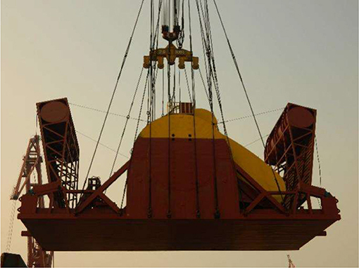
Figure 5. The modified device in hoisting.
The hydrodynamics calculations for this wave energy device are carried out in this paper. The calculation is based on the boundary element method of simple Green's function. Unlike other methods of calculation, the radiation surface condition adopts the characteristic function expands of velocity potential in the cylindrical coordinate system to guarantee the accuracy of calculation while reducing the amount of calculation. At the same time, the coupling influence between multi-bodies is considered and the velocity potential is decomposed according to the constraint conditions to ensure the authenticity of the movement. It can be applied to many kinds of articulated wave energy devices, such as the Pelamis wave device (Henderson, 2006), Oyster wave device (Whittaker and Collier, 2007), Edinburgh Duck wave device and Eagle wave device (Sheng et al., 2015). The numerical calculation of the modified Duck device is provided in section Calculation Method. The calculation results are carried out in section Calculated Results. The open sea test results are in section Open Sea Tests. The discussion and conclusions are in section Discussion and Conclusions.
By assuming the water is homogenous, incompressible and with no viscosity, the flow is irrotational, and the fluid and buoys motions are small, thus the linear potential flow theory can be applied. The fluid and the buoys have the harmonic motions under the incident wave with the circular frequency ω, and then all the time-dependent quantities can be separated. The space velocity potential ϕ can be further decomposed into:
Here, ∅I, ∅D, and ∅j are, respectively, the incident wave velocity potential, the wave diffraction velocity potential, and the radiation velocity potential when the buoys oscillates at unit speed under constraints (Zhang et al., 2018).
Due to the existence of hinged constraints the Duck-head and underwater-stabilized substrate have the same surge and heave motion, different pitching motion. Thus, there are only four motion modes in the articulated system, namely, the heave motion, the surge motion, the pitching motion of Duck-head, and the pitching motion of underwater-stabilized substrate. Therefore, in Equation (1), n takes 4. This is a modal decomposition based on constraints.
The incident wave velocity potential ∅I(x, y, z) under a limited water depth h is as follows:
where, g is gravity acceleration; A is incident wave amplitude; h is the water depth; k is the wave number, and k meets the dispersion relationship ω2 = gk tanh(kh) (Zhang et al., 2018).
Cartesian coordinates are defined with z = 0 as the plane of the undisturbed free surface and z = −h as the bottom surface. The symbols Ω, Sf, Sw, Sb, and SL represent the fluid domain, the free surface, the buoys surface, the sea-bottom surface and the radiant boundary surface, respectively. The radiant surface SL is a cylindrical surface, which surrounds the device and take the z axis as the center at a limited distance. The interior of the cylinder is the fluid domain.
The diffraction velocity potential ∅D(x, y, z) and the radiation velocity potential ∅j(x, y, z) are expressed in ∅l(x, y, z) below, which satisfies the following definite conditions:
In Equation (3), j = 1, 2, 3, 4, and nj represent the generalized normal vector of the body surface. n1 and n2 are, respectively, the partial derivative of the normal direction of the Duck-head and underwater substrate in the x-axis and z-axis directions; n3 can be computed as n3 = 0 on the underwater substrate, and on the Duck-head, where (x0, z0) is the hinge point coordinate; and and are, respectively, the normal direction of the Duck-head on the x-axis and z-axis components; n4 can be expressed as n4 = 0 on the Duck-head, and on the underwater substrate where and are the normal direction of the underwater substrate on the x-axis and z-axis components, respectively (Zhang et al., 2018).
The velocity potential ∅l and its normal derivative on the radiant surface SL are as follows (He and Dai, 1992):
where, is the first type of Hankel function and the subscript m represents the order; Km is the second type of modified Bessel function, and Km(knr) exponentially decreases with the r increase, so the item associated with Km(knr) is the local disturbance wave; k satisfies ω2 = gk tanh(kh) and kn satisfies ,bnm and cnm (n = 1, 2, …, ∞; m = 1, 2, …, ∞) are the complex coefficients to be determined.
The velocity potential and its normal derivative on the radiant surface are expressed by the unknown coefficients amn, bmn, and cmn. The control points are uniformly selected on the radiant surface SL in the z and θ directions. The number of control points on the radiant surface SL is equal to the unknown coefficients, thus these coefficients could be solved (He and Dai, 1992; Zhang et al., 2018).
To solve ∅l by the boundary element method, the boundary integral equation can be expressed as follows:
where P and Q are, respectively, the field points and source points on the boundary surfaces; S is the boundary surfaces of the entire computational domain, which can be written as S = Sf + Sb + Sw + SL; G(P, Q) is the simple Green function G = −1/4πr and r is the distance from the field point P to the source point Q. Using −1/4πr as the simple Green function, a large part of the calculation of the integral equation coefficients is independent of frequency, so it can improve the computational efficiency (Payne et al., 2008; Bracco et al., 2011; De Andres et al., 2013; Pastor and Liu, 2014; López et al., 2017).
To discretize Equation (6), the structured quadrilateral grid units are established on all boundary surfaces of the internal computing domain. For the constant element method, when surface of an object is dispersed into N plane elements, the value of solid angle α must be 1/2 and the direction derivative of the Green function is zero, thus avoiding the difficulty of calculating the solid angle coefficient and the Cauchy principal singular integral problem.
The above Equation (6) can be written as follows:
where, the coefficient matrix , δjk is the Kronecker Delta Function; and the coefficient matrix .
Substituting the given boundary conditions (3)–(5) into Equation (7), the unknown value becomes the discrete value of the velocity potential on each unit, and the complex coefficients on the surface SL. By solving the Equation (7), the velocity potential on the surfaces Sf, Sw, and Sb, and the coefficients amn, bmn, and cmn on the radiant surface SL can be obtained.
The excitation force f0k caused by the incident velocity potential and the diffraction velocity potential on the device in the k-mode motion direction is as follows:
In the j-mode motion, the radiation force fjk caused by the radiation velocity potential in the k-mode motion direction can be written as:
where ajk and bjk are, respectively, the additional mass and radiation damping caused by the j-mode motion of the device in the k-mode motion direction. The expressions of ajk and bjk are as follows:
Here, Re and Im, respectively, represent the real and imaginary part of the complex number.
Hydraulic system is installed within the device and the external damping force fk generated by the hydraulic system exists in the rotation direction between the Duck-head and underwater substrate, and the external damping force can be written as:
where, ξjis the j-modal displacement; is the coefficient matrix of the external damping force; cf is the hydraulic cylinder damping coefficient, and the matrix is as follows:
The motion equations can be written as:
where Mjk is the mass matrix, Cjk is the matrix of restoring force coefficients.
The Equation (13) is actually a complex algebraic system of equations. By solving the Equation (13), the motion displacement ξj are obtained. Thus, the output power Pw can be calculated.
The input wave power P0 in the unit width is
where, A is the incident wave amplitude; h is the water depth; λ is the wavelength; and T is the wave period.
Thus, the capture width ratio η of the device can be written as:
where, b is the width of the eagle beak.
The designed device is 6 m wide, 19.4 m long and 11.8 m high. The draft depth of the device is 9.3 m. In this calculation, the incident wave period range is 1–10 s, the wave height is 1 m and water depth is 20 m. The calculation domain radius is 30 m. The mesh size takes 5~10% of minimum wavelength according to the calculated wave conditions. The computation has been verified by grid independence and the convergence factor take 10−4.
The external damping coefficient can be adjusted by setting the hydraulic conversion system of the device. Proper selections of the external damping coefficient cf at different wave period can improve the efficiency of the device to capture wave energy. By changing the coefficient cf, the optimal capture width ratios η under different wave periods are obtained shown in the Figure 6.
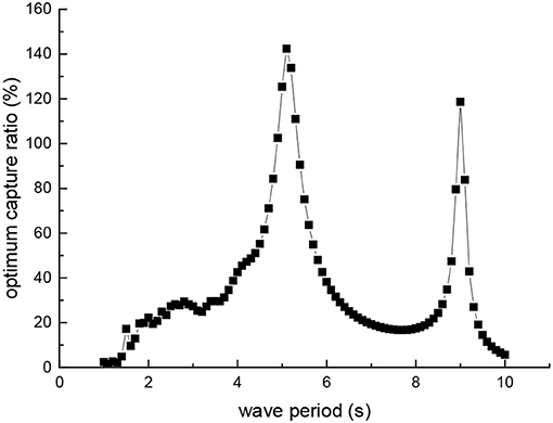
Figure 6. Optimum capture width ratio.
By calculating in frequency domain, we find out the optimum wave period for the device and the optimum damping for different wave periods. It can be seen from Figure 6 that the device has the highest capture width ratio of 142% when the wave period is 5.1 s, and a higher capture width ratio of 118% when the wave period is 9.0 s. The reason why the capture width ratio is >100% is that a wave crest wider than the device is captured. The device has the function of gathering waves. It is suitable for the wave period of about 5.1 s as the best working period of the device. Because, in the region where the capture width ratio is >40%, the wave period rang near 5.1 s is wider than the wave period 9.0 s. Moreover, when the wave period is close to 9.0 s, the wave in the test sea area belongs to the big wave, and the safety of the device is threatened. According to the working characteristics, we can better apply the device or further optimize the design of the device.
Figure 6 is obtained by selecting the optimal external damping coefficient in each wave period. The external damping coefficient is produced by the hydraulic system, and is changed by adjusting the hydraulic pressure. The optimum hydraulic damping coefficient for every wave period is shown in Figure 7.
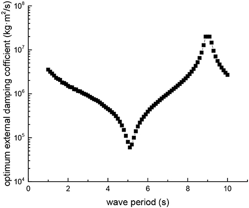
Figure 7. Optimum hydraulic damping coefficient.
It can be seen from Figure 7 that the optimum hydraulic damping coefficient of the device reaches a minimum in the wave period of 5.1 s and the maximum in the wave period of 9.0 s. The reason is that the wave excitation force in the short wave is weaker than the long wave. While the external damping is also smaller, the relative pitching motion of the device will be larger and more beneficial to the work of the device. In the long wave, the wave excitation force on the device is greater, and the device can overcome the larger external damping force to work.
Another important phenomenon from Figure 7 is that the optimum hydraulic damping coefficient varies greatly in wave period of 1–10 s, and the difference between maximum and minimum values is nearly 300 times. However, in the operation of the actual device, there is not such a large hydraulic adjustment range and the hydraulic damping adjustable range is within 10 times. Because the best working condition of the device is near the wave period of 5.1 s, the adjustable hydraulic damping range of the actual device can be selected as the hydraulic damping coefficient near the wave period of 5.1 s. This enables the device to achieve maximum efficiency near optimal working conditions, even in the wave period of 3.5–6.5 s, the hydraulic system fails to achieve optimal damping. Further, controlling the hydraulic pressure within a lower range is also advantageous for the safety of the installation.
Figures 8–11 shows the four motions of the device under the ten kinds of different external damping coefficient cf in each wave period.
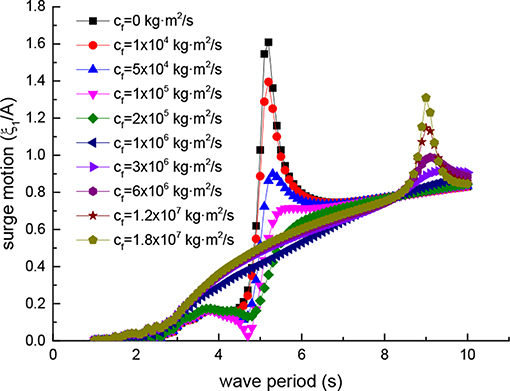
Figure 8. Surge motion.
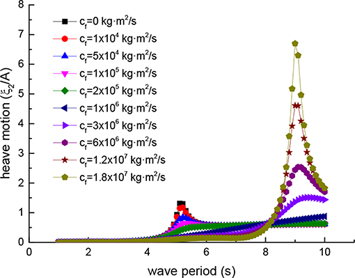
Figure 9. Heave motion.
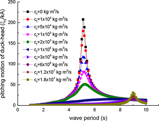
Figure 10. Pitching motion of Duck-head.
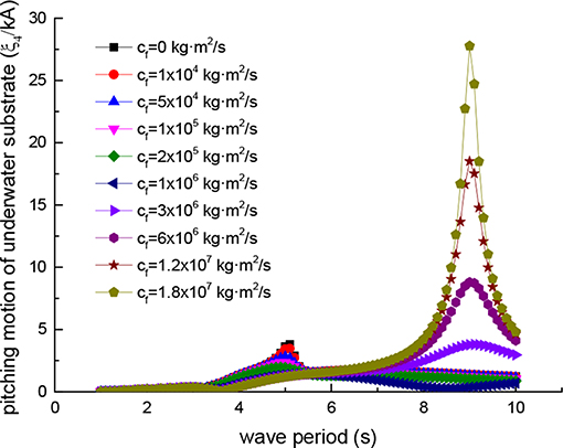
Figure 11. Pitching motion of underwater substrate.
Due to the existence of hinged constraints, the Duck-head and the underwater substrate have the same translational displacement and different rotational displacement. Figure 8 is the surge motion of the device, Figure 9 is the heave motion of the device, Figure 10 is the pitch motion of Duck-head, and Figure 11 is the pitch motion of underwater substrate. In Figures 8, 9, the ordinate is the translational displacement divided by the wave amplitude A to make dimensionless and the abscissa is wave period T. In Figures 10, 11, the ordinate is rotational displacement divided by the incident wave steepness kA to makes dimensionless and the abscissa coordinates is wave period T.
When the external damping coefficient is equal to zero, it means that the hydraulic system fails or is shut down, and the device no longer captures the wave energy. In this state, the device has the largest free motion near the wave period of 5.1 s. Especially, the pitching movement of the Duck-head is the largest shown in Figure 10. In this case, the device is in a dangerous state. Due to excessive movement, the Duck-head may easily lead to collision damage or overturning (Zhang et al., 2018). So in the actual operation of the device, this situation should be prevented.
As the external damping coefficient increases, the motion of the device near the wave period of 5.1 s gradually decreases, and the motion near the wave period of 9.0 s increases. Therefore, it is not the greater the damping coefficient, the better the effect is, and the excessive external damping coefficient should be avoided. It can lead to another dangerous wave period from one wave period.
It is important to choose the appropriate external damping coefficient, which ensures the efficiency of the device and does not lead to excessive motion. In the above mentioned, based on efficiency and reality, the external damping coefficient range near the optimal coefficient of the wave period 5.1 s is selected. Now, from the view of the device safety movement, the correctness of the external damping selection is also confirmed. The device will not produce excessive motion under this external damping. Meanwhile, it can also be seen from Figures 10, 11 that in the selected external damping range, the pitch motion of the underwater substrate is far less than Duck-head, thus achieving the proper role of the design and ensuring the stability of the device.
By calculating in frequency domain, we have a general understanding of the performance of the device. We found out the optimum wave period of the device and the setting of the hydraulic conversion system in different wave periods.
The actual size of the modified Duck device is the same as the size of the calculation, and the device configures 2 sets of permanent magnet generators (30 and 70 kW). According to real sea conditions, the device can automatically adjust these generators. Power output of the device varies from different hydraulic pressure. As the device reached the target site (22°56N, 115°41E), four 200 m long anchor chains are dropped around the device, respectively (Sheng et al., 2017).
The test area is located near the sea of WanShan Islands in Zhuhai, China. This sea area has relatively abundant wave energy resources in China, and belongs to the special test field of ocean energy stipulated by the government of China. The waves here are from various directions with annual wave energy flux density of 4 kW/m. In winter season, wave energy flux density reaches 4–10 kW/m, while in summer season, it is about 1–6 kW/m (Chen et al., 2003, 2016; Zhang et al., 2014; Sheng et al., 2017). In the test area, the common wave period is between 3.5 and 6 s, and the common wave height is between 0.2 and 1.8 m. The depth of the test area is 20 m.
The test lasted 10 days from April 17th to 29th. During this time, waves are not so strong. The sea condition during the test is shown in the Figures 12, 13. The wave height H1/3 denotes significant wave height, while wave period T1/3 is the corresponding significant wave period.
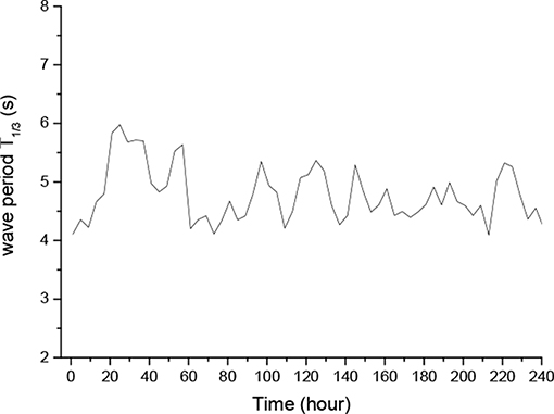
Figure 12. Wave period of test time.
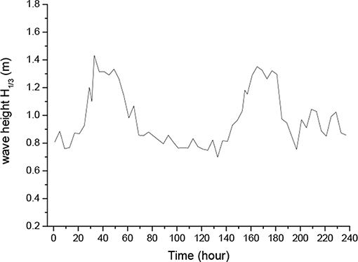
Figure 13. Wave height of test time.
It can be seen that the wave period during the test time is between 4–6 s and the wave height is between 0.8 and 1.4 m. This is precisely the range of the optimum wave period of the device that we have calculated from the frequency domain, and within this range, the excellent performance of the device in the real sea shows the rationality of our design. In this test, resistance is the major loading of the generator and most of the electrical energy is for resistance consumption. By measuring the output voltage and current, the output power of the device over time is shown in Figure 14 and the daily output power of the device during the test is shown in Figure 15.
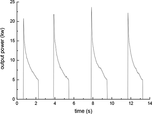
Figure 14. Output power.
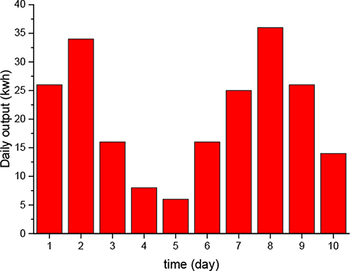
Figure 15. Daily generated output bar chart.
It can be seen from Figure 14 there are four work cycles of the device within 14 s. Power is gradually reduced from 20 to 5 kW within a single work cycle, and the individual work cycle of the device is around 4 s, which is roughly the same as the period of the wave. This is because in the first half of the wave period, the motion of the device pushes the hydraulic oil out, thus drives the generator to generate electricity, and in the last half of the wave period, the motion of the device complements hydraulic oil for the hydraulic cylinder, preparing for the next work cycle.
Figure 15 shows the power generation per day during the test. The device generates the maximum output on the eighth day, reaching 38 kWh, and at least 6 kWh on the fifth day. The total power generation for 10 days is 207 kWh. The daily output power is not stable, and it is related to the wave. As a result, it is suggested that other renewable energy sources, such as solar and wind energy, can use the device as a carrier, and complement with wave energy to realize the stable output of energy.
This paper introduces a modified Edinburgh Duck wave energy converter. The modified device uses a new underwater stabilized substrate. While effectively ensuring the stability of the device, it also facilitates the transportation and construction at sea, thus reducing the costs. This design can be used as a reference for similar wave energy converters.
A numerical approach was developed allowing to expand the characteristic function and combine the velocity potential in the cylindrical coordinate with a BEM solver, to solve multi-body coupling motion problems of buoys with complex shapes which can be applied to many articulated wave energy devices. In addition, due to the velocity potential are distributed on all the boundaries to describe the fluid domain, there is no limit to the boundary condition.
By optimizing the important parameter hydraulic damping coefficient, the optimum efficiency curve of the device is obtained. Through the curve, it is known the device has the highest capture width ratio in wave period 5.1 and 9.0 s. Subsequent open sea test also proved this point. The device has good power generation capacity when the wave period is about 5 s. Then the optimum damping curves under different wave periods are obtained. Because the optimum damping range is large, it is necessary to put forward a widely adjustable hydraulic system that can automatically adapt to the wave period.
The motion of the device is also obtained by calculation, which is affected by the hydraulic damping coefficient. According to this result, dangerous condition of damage to the device were analyzed. A small damping coefficient should be avoided at a wave period of 5.1 s and a large damping coefficient should be avoided at 9.0 s, all of which will lead to excessive motion of the device. The excessive motion may cause collision damage. Therefore, the hydraulic damping coefficient is not only important to improve the capture width ratio of the device, but also plays an important role in the safety of the device. The appropriate selection of hydraulic damping coefficient is of great significance to the device. The choice of hydraulic damping coefficient should take into account the safety and efficiency.
After construction in the shipyard, the sea test was carried out near the north of the South China Sea. Power curves and daily power generation had been obtained. The power curve shows that work cycle of the device is close to the wave period. So, the fatigue of moving parts should be noted at the beginning of design. In addition, the instability of the wave results in the unstable output of the hydraulic system. It can be considered to add energy storage in the hydraulic system and turn the unstable hydraulic output into stable output. The device could also be used as the carrier for other renewable energy on the sea, thus realizing the efficient and complementary utilization of energy.
The datasets generated for this study are available on request to the corresponding author.
CZ and SH undertook the main research work. YY and SS guided the research work of CZ.
This study was supported by the National Science Foundation of China (Grant No. 51609232), the Strategic Priority Research Program of the Chinese Academy of Sciences (Grant No. XDA13040203), the Floating Support Platform Project (No. 201622), High-tech Ship Research projects sponsored by Ministry of Industry and Information Technology, and the Marine Renewable Energy Funds Projects (GHME2017SF01 and GHME2017YY02), to which the authors are most grateful.
The authors declare that the research was conducted in the absence of any commercial or financial relationships that could be construed as a potential conflict of interest.
Bergdahl, L. (1992). “Review of research in Sweden,” in Proceedings of the Wave Energy Workshop (Cork).
Bracco, G., Giorcelli, E., and Mattiazzo, G. (2011). ISWEC: a gyroscopic mechanism for wave power exploitation. Mech. Mach. Theor. 46, 1411–1424. doi: 10.1016/j.mechmachtheory.2011.05.012
Chen, A., You, Y. G., Sheng, S. W., Lin, H., Ye, Y., and Huang, S. (2016). Nonlinear analysis of the crashworthy component of an eagle wave energy converter in rotating-collision. Ocean Eng. 125, 285–294. doi: 10.1016/j.oceaneng.2016.08.025
Chen, Y., Wai, O. W. H., and Li, Y. S. (2003). Numerical model for wave refraction-diffraction near Pearl River Estuary, China. J. Waterway Port Coast. Ocean Eng. 129, 260–269. doi: 10.1061/(ASCE)0733-950X(2003)129:6(260)
De Andres, A., Guanche, R., Armesto, J., Del Jesus, F., Vidal, C., and Losada, I. (2013). Time domain model for a two-body heave converter: model and applications. Ocean Eng. 72, 116–23. doi: 10.1016/j.oceaneng.2013.06.019
Fredrikson, G. (1992). “IPS wave power buoy Mark IV,” in Proceedings of the Wave Energy Workshop (Cork).
Gadonneix, P., Medeiros, N. F. D., and Drouin, R. (2009). Officers of World Energy Council. London: Survey of Energy Resources.
He, W., and Dai, Y. (1992). The simple Green function technique for calculating the hydrodynamic forces acting on a body without forward speed. J. Hydrodynam. 7, 449–456.
Henderson, R. (2006). Design, simulation, and testing of a novel hydraulic power take-off system for the Pelamis wave energy converter. Renew. Energy 31, 271–283. doi: 10.1016/j.renene.2005.08.021
López, M., Taveira-Pinto, F., and Rosa-Santos, P. (2017). Influence of the power take-off characteristics on the performance of CECO wave energy converter. Energy 120, 686–697. doi: 10.1016/j.energy.2016.11.121
Nebel, P. (1992). Maximizing the efficiency of wave-energy plants using complex conjugate control. Proc. I Inst. Mech. Eng. Part I J. Syst. Control Eng. 206, 225–236.
Pastor, J., and Liu, Y. (2014). Power absorption modeling and optimization of a point absorbing wave energy converter using numerical method. J. Energy Resour. Technol. 136:021207. doi: 10.1115/1.4027409
Payne, G. S., Taylor, J. R., Bruce, T., and Parkin, P. (2008). Assessment of boundary-element method for modelling a free-floating sloped wave energy device. Ocean Eng. 35, 342–357. doi: 10.1016/j.oceaneng.2007.10.008
Salter, S. H. (1980). Recent progress on ducks. IEE Proc. A 127, 308–319. doi: 10.1049/ip-a-1.1980.0049
Salter, S. H. (1989). World progress in wave energy−1988. Int. J. Ambient Energy 10, 3–24. doi: 10.1080/01430750.1989.9675119
Salter, S. H., Cruz, J., Lucas, J., and Pascal, R. (2007). “Wave powered desalination,” in International Conference on Integrated Sustainable Energy Resources in Arid Regions (Abu Dhabi).
Salter, S. H., Jeffrey, D. C., and Taylor, J. R. M. (1976). The architecture of nodding duck wave power generators. Nav. Archit. 1, 21–24.
Sheng, S., Wang, K., Lin, H., Zhang, Y., You, Y., Wang, Z., et al. (2017). Model research and open sea tests of 100 kW wave energy convertor Sharp Eagle Wanshan. Renew. Energy 113, 587–595. doi: 10.1016/j.renene.2017.06.019
Sheng, S. W., Zhang, Y. Q., Wang, K. L., and Wang, Z. P. (2015). Research on wave energy converter sharp eagle I. Ship Eng. 37, 104–108. doi: 10.13788/j.cnki.cbgc.2015.09.104
Whittaker, T., and Collier, D. (2007). “The construction of Oyster near shore surging wave energy converter,” in 7th European Wave and Tidal Energy Conference (Porto).
Zhang, C., You, Y. G., and Chen, A. J. (2018). Hydrodynamics research of a two-body articulated wave energy device. Ocean Eng. 148, 202–210. doi: 10.1016/j.oceaneng.2017.11.029
Keywords: wave energy converter, numerical modeling, open sea tests, modified Edinburgh Duck, motion constrains
Citation: Zhang C, Huang S, You Y and Sheng S (2019) Numerical Research and Open Sea Tests of a 100 kW Modified Edinburgh Duck Wave Energy Convertor. Front. Energy Res. 7:120. doi: 10.3389/fenrg.2019.00120
Received: 30 August 2019; Accepted: 11 October 2019;
Published: 29 October 2019.
Edited by:
Binzhen Zhou, Harbin Engineering University, ChinaReviewed by:
Xiongbo Zheng, Harbin Engineering University, ChinaCopyright © 2019 Zhang, Huang, You and Sheng. This is an open-access article distributed under the terms of the Creative Commons Attribution License (CC BY). The use, distribution or reproduction in other forums is permitted, provided the original author(s) and the copyright owner(s) are credited and that the original publication in this journal is cited, in accordance with accepted academic practice. No use, distribution or reproduction is permitted which does not comply with these terms.
*Correspondence: Shuo Huang, aHVhbmdzaHVvQG1zLmdpZWMuYWMuY24=
Disclaimer: All claims expressed in this article are solely those of the authors and do not necessarily represent those of their affiliated organizations, or those of the publisher, the editors and the reviewers. Any product that may be evaluated in this article or claim that may be made by its manufacturer is not guaranteed or endorsed by the publisher.
Research integrity at Frontiers
Learn more about the work of our research integrity team to safeguard the quality of each article we publish.