 Guangzong Zheng
 Bo Chen3
 Kaiyi Shi
95% of researchers rate our articles as excellent or good
Learn more about the work of our research integrity team to safeguard the quality of each article we publish.
Find out more
ORIGINAL RESEARCH article
Front. Energy Res. , 04 June 2019
Sec. Nuclear Energy
Volume 7 - 2019 | https://doi.org/10.3389/fenrg.2019.00051
This article is part of the Research Topic Nuclear Safety Design and Innovation View all 14 articles
As the core device of a filtered containment venting system (FCVS), Venturi Scrubber is an efficient device to scrub the radioactive gases and aerosols before release into the atmosphere. The design concept of Multi-Venturi Scrubber System makes the laboratory-scale venturi scrubber research more valuable. This paper studied the injection flow rate of Venturi Scrubber in different injection arrangements. The liquid is injected horizontally and vertically to the throat at different radial position of (i) at the wall of throat, (ii) at the half radius of throat, and (iii) at the center of Venturi Scrubber throat with a nozzle of diameter 4 mm. Throat gas velocities range from 0 to 190 m/s. A constant level water tank was installed to keep water level constant during the injection process. The results showed that liquid injection modes significantly affect the injection performance. The arrangements of straight tube at center and elbow tube at center had larger injection flow rate among the others, and the injection flow rate increased as the throat gas velocity increased. The conventional wall opening (i.e., straight tube at the wall) injection method had the worst injection performance. This study provides a valuable reference for the liquid injection arrangement and structural design of the Venturi Scrubber.
As the core device of a filtered containment venting system(FCVS), Venturi Scrubber is an efficient device to scrub the airborne source items before release into the atmosphere. The radioactive airborne source items mainly contain aerosol, iodine and methyl iodide (Eckardt and Losch, 2012). A Venturi Scrubber has convergent section, throat section, and divergent section. Due to small cross-sectional area of the throat, the air velocity reaches the maximum at the Venturi Scrubber throat. Under the action of the shear force of the high-speed airflow, the injection water is atomized into numerous small droplets, which provide a sufficient surface area for dedusting (Hills, 1995; Das and Biswas, 2006). The airborne sources contact with the droplet surface and settle inside the droplets. This process contains many mechanisms, including inertial collision, interception capture, diffusion capture, gravity sedimentation, and electrostatic adsorption (Pulley, 1997;Ali et al., 2013).
Venturi Scrubbers are widely used in industry because of their simple structure and high dust removal efficiency (Rudnick et al., 1986; Talaie et al., 1997; Ahari et al., 2008). Early studies of Venturi Scrubbers focus on internal two-phase flow, including jet characteristics (submergence depth, jet velocity, jet diameter, and jet trajectory, etc.) and droplet characteristics (initial droplet concentration, droplet size, and droplet velocity, etc.). In engineering, researches focus on the effect of operating parameters and structural parameters on injection flow rate and filtration efficiency. The operating parameters include gas flow rate, operating pressure and submergence depth, etc. The structural parameters contain throat length, divergent section angle and the placement of the ejector tube, etc. Many people studied the different structural parameters of the Venturi Scrubber including area ratio, projection ratio, divergent angle, throat length, and convergent section shape, to explore the performance of the Venturi Scrubber (Kroll, 1947; Panchal et al., 1991; Cramers and Beenackers, 2001; Sriveerakul et al., 2007; Yadav and Patwardhan, 2008). Das and Biswas (2006) proposes that the filtration efficiency of the Venturi Scrubber is closely related to its structure design including the suction chamber, the mixing throat, the divergent diffuser, the forcing nozzle, and divergence angle, etc. Zhou et al. (2015) explores the effect of operating conditions and structures on the removal of aerosols in the Venturi Scrubber. The study finds that the retention efficiency in a Venturi Scrubber increases with the increase of both gas velocity and injection flow rate, and the influence of gas velocity on efficiency is more effective at low injection flow rate. Moreover, the Venturi Scrubber with a long throat length or small diffuser angle performs excellent retention performance for small size aerosols.
Westinghouse offers the FILTRA-MVSS (Multi-Venturi Scrubber System) to effectively mitigate the consequences of a severe reactor accident by signifcantly reducing the level of radioactive release to the surrounding environment (Westinghouse Electric Company, 2012). The number of Venturi Scrubbers in operation is determined by the actual mass flow. This design method can maintain high throat gas velocity and injection flow rate of each Venturi Scrubber.
The aim of this paper is to present some experimental analysis of the effect of different liquid injection arrangements on injection flow rate of a self-priming Venturi Scrubber. The experiment is carried out using two types of tubes, straight tubes and elbow tubes. The liquid is injected into the throat of the Venturi Scrubber parallel or perpendicular to the airflow at different radial position of (i) at the wall of throat, (ii) at the half radius of throat, and (iii) at the center of Venturi Scrubber throat. Firstly, the injection flow rate of 6 different injection methods is measured under several operating conditions. Then, the range of working conditions are expanded for the configurations of straight and elbow tubes at center, which have advantages in injection performance. And the influence of throat gas velocity and submergence depth are investigated. As a comparison of the above two types of injection, the conventional wall opening configuration(straight tube at the wall of throat) is also studied at the same time. This study provides a valuable reference for the liquid injection arrangement and structural design of the Venturi Scrubber.
A schematic illustration of the experimental loop is shown in Figure 1. The system is mainly composed of screw air compressors, air tank, air filters, different types of valves, mass flowmeter, Venturi Scrubber, constant level tank, weigh, and lifter. The air compressors provide a stable gas source to the system with flow rate of 10~1,200 kg/h. After the gas flow is buffered in the air tank and enters the experimental pipeline, it flows through air filters, shutoff valve, mass flowmeter, throttle valve, check valve, and finally into the Venturi Scrubber. The injection water from the constant level water tank is atomized into small droplets under the effect of high-speed air shear force in the Venturi Scrubber throat, which provides a sufficient surface area for dust removal.
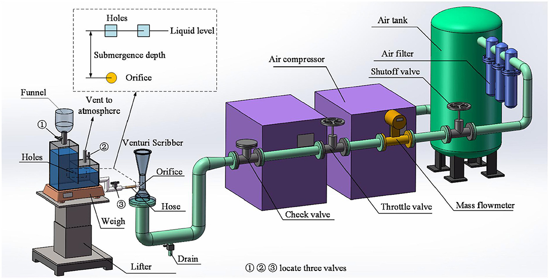
Figure 1. Schematic diagram of experimental loop.
The water tank designed in this experiment can maintain a constant water level while supplying water for the Venturi Scrubber. The injection flow rate can be obtained by measuring the water tank weight at different times. When the water tank provide liquid to the Venturi Scrubber, it calls for the valve① closed, the valve② and valve③ open. At this time, the right chamber of the water tank vents to the atmosphere while the left chamber does not. The water level on the right side of the Venturi Scrubber maintains constant while the left side level drops gradually. The difference in height between the right chamber water level to the injection orifice of the Venturi Scrubber becomes submergence depth, supplying power to liquid injected. The constant level tank, connecting to the injection tube of the Venturi Scrubber through rubber hose, is placed on the weighing device with weight measurement accuracy to 0.1 g, and can realize submergence depth adjustable by manipulating the lifter.
The equipment used in the experimental tests was a Venturi Scrubber constructed of acrylic, with a circular cross-section and throat dimensions of diameter 24 mm. Liquid was injected into the throat through six different nozzle arrangements. The main dimensions and nozzle arrangements of the Venturi Scrubber are shown in Figure 2. The gas velocity at the Venturi Scrubber throat is evaluated in the present study as follows.
Mg is the gas mass flow rate. ρg,th is the throat gas density and Athrepresents the throat cross-sectional area. Contrary to conventional method with orifice in throat, the liquid was injected horizontally and vertically to the throat with nozzles of 4 mm diameter at different radial positions. The nozzle positions were located on the wall surface, 0.5 times radius and the central axis of the Venturi Scrubber throat.
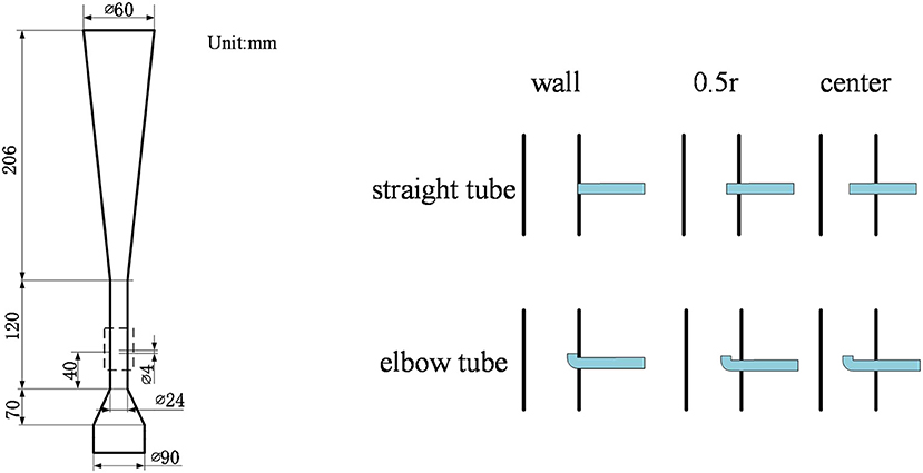
Figure 2. Dimensions and nozzle arrangements of the Venturi Scrubber.
Air was supplied by the air supply line and the flow rate could be measured. After the air compressor achieved desired pressure 0.7 Mpa, the shutoff valve and throttle valve were opened in turn. The gas flow rate was adjusted to a certain value by controlling the throttle valve. Gas flow rate values were measured by mass flowmeter and recorded by computer.
The constant level water supply system was capable of supplying water of a constant submergence depth to the Venturi Scrubber and measuring the injection flow rate. When offering water to the Venturi Scrubber, valve① was closed, and valve②③ were open. The liquid level in the right chamber was constant and parallel to the small holes. The bubble entered the left chamber through the small holes, and the liquid level in the left chamber gradually decreased. The injection flow rate can be calculated by measuring the weight difference of the water tank and time. Operating parameter ranges are shown in Table 1.
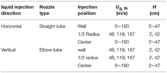
Table 1. Experimental operating parameters.
The effect of liquid injection arrangements was carried out using two types of tubes (straight tubes and elbow tubes), and three radial positions (i.e., wall, 0.5r and center of the Venturi Scrubber throat). Section Effect of Radial Positions and Type of Injection Tubes involves the effect of radial positions and type of injection tubes. After that, three particular nozzle arrangements (i.e., straight tube at the wall, straight tube at the center, and elbow tube at the center) concerned were further studied, considering the influence of throat gas velocity and submergence depth. Injection characteristics of the three nozzle arrangements were studied in section The Influence of Throat Gas Velocity under different throat gas velocity, which, respectively, took place at three submergence depths. Section The Influence of Submergence Depth focuses on the influence of varied submergence depths.
Figures 3, 4 show the effect of radial positions and type of injection tubes on injection flow rate under particular throat gas velocity and submergence depth. It is found that the injection flow rate, with the same nozzle radial position but two different types of tubes, straight and elbow tubes, shows an increasing trend as nozzle radial positions vary from wall, 0.5r and the center. This is due to the highest gas velocity at the center of the throat, and the lowest velocity at the wall due to the presence of the boundary layer. Correspondingly, the center of the throat produces a greater negative pressure than the wall surface, providing more power for injection water. Although the nozzles locating at the center always prevail in injection flow rate, it still remains a question which tube, straight or elbow, acts better under certain operating parameters. In Figures 3B,C, 4C, the elbow tubes, compared to straight tubes, prevail in injection flow rate at the same position, while in Figure 4A, the elbow tubes are at a disadvantage in injection flow rate. Particularly, the injection flow rate curves of the two types of tubes cross in Figures 3A, 4B. It can be clearly seen that whether straight tubes or elbow tubes prevail in injection flow rate is a complicated process, which is an effect of the coupling of throat gas velocity and submergence depth. Still, many implicit rules can be obtained after analysis. It reveals that, as throat gas velocity increases, the injection flow rate of elbow tubes at the same radial position does not dominate at first and gradually exceeds the straight tube, as is shown in Figures 4A–C. Figures 3A–C shows the same law as well. Comparing injection flow rate (nozzle at the throat center) in Figures 3B, 4B, it can be seen that with the increase of the submergence depth from 2 to 42 cm, the injection flow rate of straight tube does not dominate in the beginning and finally exceeds the elbow tube. It indicates that, although the effect of injection flow rate is a complicated process of coupling of throat gas velocity and submergence depth, the increase of the throat gas velocity is more conducive to the elbow tubes, while the increase of submergence depth is more conducive to the straight tubes.
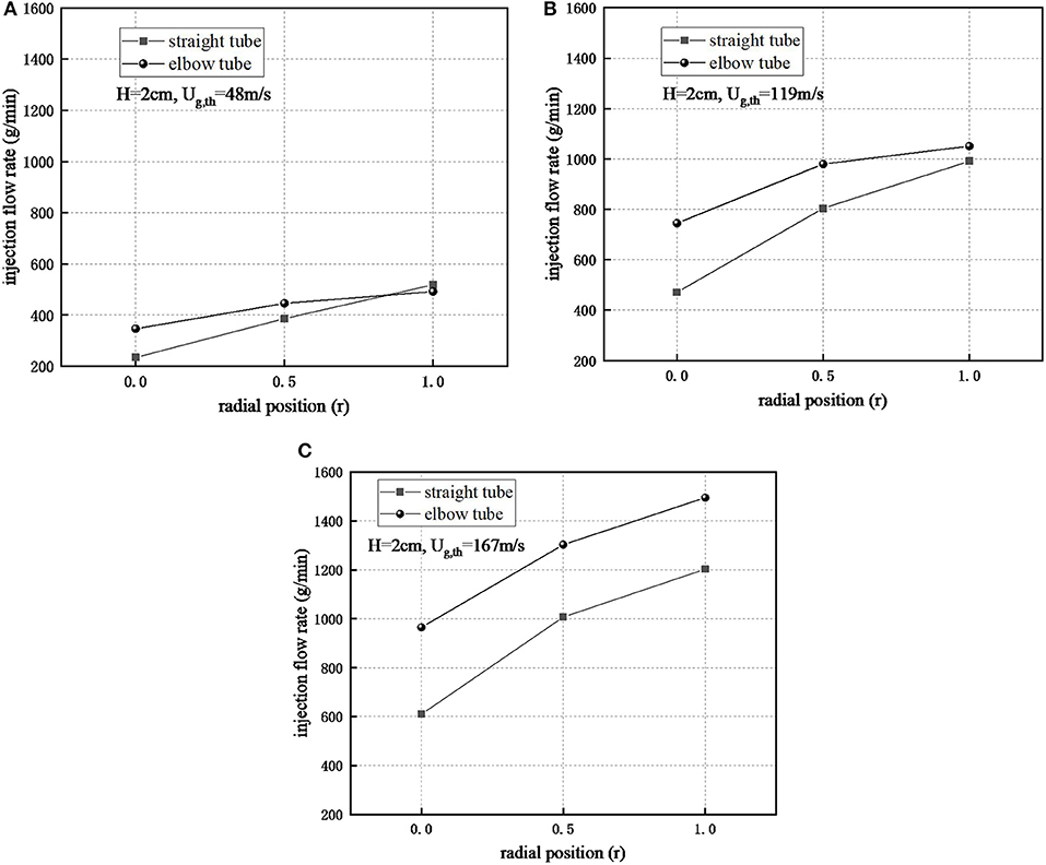
Figure 3. Injection flow rate at submergence depth of 2 cm. (A) H = 2 cm, Ug,th = 48 m/s, (B) H = 2 cm, Ug,th = 119 m/s, (C) H = 2 cm, Ug,th = 167 m/s.
Figure 4. Injection flow rate at submergence depth of 42 cm. (A) H = 42 cm, Ug,th = 48 m/s, (B) H = 42cm, Ug,th = 119 m/s, (C) H = 42 cm, Ug,th = 167 m/s.
Due to the study in section Effect of Radial Positions and Type of Injection Tubes on six different nozzle arrangements, in which the injection flow rate of two types of tubes at the center always dominates, it is necessary to do further research on the central straight tubes and elbows. The configuration of the straight tube at the wall is also taken into consideration as a reference, which is mainly due to the fact that the straight tube at the wall is a structure commonly adopted by the traditional Venturi Scrubber. Figures 5A–C show the injection flow rate curves of three nozzle arrangements (i.e., straight tube at the center, elbow tube at the center, and straight tube at the wall) as throat gas velocity changes, which are developed at submergence depths of 2, 12, and 42 cm, respectively. It can be clearly found that, with the increase of throat gas velocity, the injection flow rate of the straight tube and elbow tube at the center is significantly higher than that of the straight tube at the wall, and the greater the throat gas velocity is, the more obvious the advantages will be. When the throat gas velocity is 190 m/s and the submergence depths are 2, 12, and 42 cm, the elbow tube at the center, compared with the traditionally adopted straight tube at the wall, can increase the injection flow rate by 2.6, 2.3, and 2 times, respectively. Meanwhile, it can be found that under the condition of global throat gas velocity, the injection flow rate of straight tube at the center is always larger than the straight tube at the wall. This meets and reinforces the discovery in section Effect of Radial Positions and Type of Injection Tubes that for the same type of tube, as nozzle position moves closely to the throat center, the injection flow rate increases.
Figure 5. Influence of different throat gas velocity on injection flow rate. (A) H = 2 cm, (B) H = 12 cm, (C) H = 42 cm.
The detail that cannot be ignored is that when the throat gas velocity is very low, compared with the straight tube at the wall, the injection flow rate of the elbow tube at the center is not dominant. As the throat gas velocity increases, the elbow tube at the center begins to reverse the straight tube at the wall, thus resulting in an intersection of the curves. And the intersections move backward with the increase of submergence depth, that is, as the submergence depth increases from 2, 12–42 cm, the intersection occurs at throat gas velocity of 14, 31, and 59.5 m/s, respectively. This is due to the shape resistance of the elbow, so that when the throat gas velocity is low, the injection flow rate of the elbow tube at the center is lower than that of the straight tube at the wall under the same operating parameters. It can be seen from Figures 5A–C where the throat gas velocity is 0, that the difference in the injection flow rate between the two types of nozzle arrangements is more pronounced as the depth of submergence increases. When the submergence depth is 42 cm, a difference of 960 g/min between the two arrangements is generated, which is due to the increase of submergence depth, making the effect of the elbow tube shape resistance more prominent. Accordingly, greater throat gas velocity is need as a counteracting of elbow tube shape resistance, to make the elbow tube at the center overtake the straight tube at the wall, which also explains why the previously mentioned increase of submergence depth makes the backward moving of intersection.
Comparing the straight tube and elbow tube both at the center, it is found that when the throat gas velocity is low, the elbow tube is not dominant. As the throat gas velocity gradually increases, the injection flow rate of the elbow tube gradually exceeds that of the straight tube. The intersections in Figure 5A wherein the submergence depth is 2 cm are more complicated, especially when the throat gas velocity is in the range from 24 to 71 m/s. In Figures 5B,C, however, intersections occur at throat gas velocity of 59.5 and 124 m/s, respectively. This is also the result of the coupling effect of the elbow tube shape resistance, submergence depth and throat gas velocity.
It is worth noting that by observing the injection flow rate curve of the straight tube at the wall in Figures 5A–C, it is found that the injection flow rate shows different trends at different submergence depths. When the submergence depth is low, i.e., 2 cm, the injection flow rate generally increases with the increase of throat gas velocity, while the injection flow rate decreases when the submergence depth is high, i.e., 42 cm. The overall injection flow rate change is small when the submergence depth is 12 cm. This signals that for a straight tube at the wall, increasing the throat gas velocity does not necessarily contribute to the increase of injection flow rate. Nevertheless, from the point of view of the injection flow rate under different submergence depths, the injection flow rate under the high submergence depth always dominates, despite the different trends under different submergence depths. This newly discovered phenomenon, wherein the underlying causes are related to internal two-phase flows and flow fields, needs further exploration.
The above studies were conducted at several submergence depths, and the injection flow rate often showed different trends under different submergence depths. From the above studies, it is also found that, with different throat gas velocity, the submergence depth seems to always promote the increase of injection flow rate. Since the above studies are merely conducted at several submergence depths, it is necessary to study the conditions at more depths of submergence. Figures 6A–C show the injection flow rate trend with the submergence depth in three nozzle arrangements (i.e., straight tube at the center, elbow tube at the center, and straight tube at the wall), at an throat gas velocity of 48, 119, and 167 m/s. It can be clearly seen that the injection flow rate of different nozzle arrangements increases as the submergence depth increases. However, the injection flow rate curves in Figure 6A, compared with those in Figures 6B,C, are not significantly different from each other, while the injection flow rate of straight tube and elbow tube both at the center in Figures 6B,C, compared to that of straight tube at the wall, has obvious advantages.
Figure 6. Influence of different submergence depth on injection flow rate. (A) Ug,th = 48 m/s, (B) Ug,th = 119 m/s, (C) Ug,th = 167 m/s.
In Figure 6A, the injection flow rate of the straight tube at the center, despite the slight advantage, is generally higher than that of the elbow tube at the center and the straight tube at the wall. While the injection flow rate of elbow tube at the center, compared to that of straight tube at the wall, prevails at first and then is overtaken by that of straight tube at the wall when submergence depth reaching 22 cm. The above phenomena are caused by the radial pressure distribution generated by gas flow in the Venturi Scrubber throat and elbow tube shape resistance. The shape resistance of the elbow tube hinders the flow of water in the elbow tube, wherein the process is affected by the submergence depth and the throat gas velocity. That is, the higher the submergence depth is, the more obviously the effect of shape resistance behaves, and the greater the throat gas velocity is, the less the effect becomes. In Figure 6A, the throat gas velocity is relatively low (48 m/s), the radial pressure distribution at the Venturi Scrubber throat is not obvious enough. Nevertheless, the injection flow rate of the straight tube at the center, due to the radial pressure distribution, is still higher than that of straight tube at the wall.
As for the elbow tube at the center, the injection flow rate of which is lower than that of the elbow tube at the center, the shape resistance emerges in it, so that the elbow tube does not dominate over the straight tube under the same operating parameters. The existence of the elbow tube shape resistance also explains the phenomenon that after the submergence depth exceeds 22 cm, the injection flow rate of the elbow tube at the center is overtaken by that of the straight tube at the wall. Before the submergence depth reaches 22 cm, the radial pressure distribution of the throat make the elbow tube prevail in injection flow rate, despite the relatively low throat gas velocity. As the submergence depth grows, shape resistance of the elbow tube start to merge, resulting in the injection flow rate of central elbow tube being overtaken by straight tube at the wall. It should be noted that the throat gas velocity at this time is still small, equaling to 48 m/s. When throat gas velocity is 119 or 167 m/s, as is shown is Figures 6B,C, raising the submergence depth does not make the injection flow rate of the straight tube at the wall catch up with that of elbow tube at the center. This is due to the large throat gas velocity hinders the effect of elbow tube shape resistance, and increasing the submergence depth within the experimental range (2–42 cm) is insufficient to make the elbow tube shape resistance effect appear.
It should be pointed out that the above comparison has a non-negligible disadvantage for the straight tube at the wall. That is, the negative pressure at the wall caused by the radial pressure distribution is significantly lower than that at the center, so that the injection power at the wall is lower than that at the center. When comparing the straight tube and elbow tube both at the center, as is shown in Figure 6B where the throat gas velocity is 119 m/s, the injection flow rate of central straight tube reverses that of elbow tube as the submergence depth rises to 37 cm. The same phenomenon occurs in Figure 6C where the throat gas velocity is 167 m/s. When raising the submergence depth to 47 cm, the injection flow rate of the straight tube at the center surpasses that of the elbow tube. Thus, the comparison of straight tube and elbow tube both at the center also proves the existence and role of the elbow tube shape resistance.
In this study, effect of six nozzle arrangements on injection flow rate were studied. Particularly, three nozzle arrangements, i.e., straight tube at the center, elbow tube at the center and straight tube at the wall were further examined, considering the influence of varied operating parameters of throat gas velocity and submergence depth. Conclusions are summarized as follows.
1) Water injection arrangements affect the injection flow rate significantly. For the straight tube or elbow tube, the closer the injection position is to the center of the Venturi Scrubber throat, the greater the injection flow rate will become.
2) Compared with the traditional wall opening configuration (i.e., straight tube at the wall), using the straight tube or elbow at the center could significantly increase the injection flow rate to more than 2 times. As the throat gas velocity increases, the injection performance of the elbow tube at the center exceeds that of the straight tube at the center.
3) When the submergence depth is high (42 cm), the throat gas velocity acts as an inhibitory effect on the injection flow rate of the straight tube at the wall.
4) Raising the submergence depth provides greater injection power, which increases the injection flow rate regardless of which injection method is used.
GZ, as the main executor of the project, participated in the facility construction, experiment, analysis, and thesis writing. BC, as a number of my lab and now graduated, help me analysis the experimental results, including different nozzle arrangements' effect on injection. JL, as a member of my lab, assisted me in the whole process, including the reading of experimental data and the construction of the test bench. KS, help me build data acquisition system. Many of his suggestions helped me improve the design of the Venturi scrubber. HG, my teacher, also expert in the field of filtered containment venting system, give me some key guidance on the experimental process.
These authors are profoundly grateful to the financial supports of the Fundamental Research Funds for the Central Universities (NO. HEUCFM181203). This work is also supported by Key Supported Discipline of Guizhou Provence (Qian Xuewei He Zi ZDXK[2016]24), 2011 Collaborative Innovation Center of Guizhou Province (Qian Jiao He Xietongchuangxin Zi [2016]02).
BC was employed by company China Nuclear Power Engineering Co., Ltd.
The remaining authors declare that the research was conducted in the absence of any commercial or financial relationships that could be construed as a potential conflict of interest.
H submergence depth, cm
Mg gas flow rate, kg/h
Ml injection flow rate, g/min
Ug,th throat gas velocity, m/s
ρg,th throat gas density, m/s
Ath throat cross-sectional area, m2
Subscripts
g gas
l liquid
th throat
Ahari, J. S., Forsat, K., Djenab, M. H., Mohammadbigy, K., Vahidi, M., and shafiei, Z. (2008). Predictive model of hydrogen sulfide absorption by chelate solution in a venturi scrubber. Chem. Eng. Technol. 31, 1481–1486. doi: 10.1002/ceat.200800135
Ali, M., Yan, C., Sun, Z., Gu, H., and Mehboob, K. (2013). Dust particle removal efficiency of a venturi scrubber. Ann. Nuclear Energy 54, 178–183. doi: 10.1016/j.anucene.2012.11.005
Cramers, P. H. M. R., and Beenackers, A. C. C. M. (2001). Influence of the ejector configuration, scale and the gas density on the mass transfer characteristics of gas - liquid ejectors. Chem. Eng. J. 82, 131–141. doi: 10.1016/S1385-8947(00)00363-6
Das, S. K., and Biswas, M. N. (2006). Studies on ejector-venturi fume scrubber. Chem. Eng. J. 119, 153–160.
Eckardt, B., and Losch, N. (2012). “Filtered containment venting system designs,” in NRC Meeting on Containment Venting Systems (Rockville, MD).
Hills, J. H. (1995). Behavior of venturi scrubbers as chemical reactors. Indus. Engineering Chem. Res. 34, 4254–4259.
Panchal, N. A., Bhutada, S. R., and Pangarkar, V. G. (1991). Gas induction and hold-up characteristics of liquid jet loop reactors using multi orifice nozzles. Chem. Eng. Commun. 102, 59–68.
Rudnick, S. N., Koehler, J., Martin, K. P., Leith, D., and Cooper, D. W. (1986). Particle collection efficiency in a venturi scrubber: comparison of experiments with theory. Environ. Sci. Technol. 20, 237–242. doi: 10.1021/es00145a002
Sriveerakul, T., Aphornratana, S., and Chunnanond, K. (2007). Performance prediction of steam ejector using computational fluid dynamics: part 1. validation of the CFD results. Int. J. Therm. Sci. 46, 812–822. doi: 10.1016/j.ijthermalsci.2006.10.014
Talaie, M. R., Fathikalajahi, J., and Taheri, M. (1997). Mathematical modeling of SO2 absorption in a Venturi Scrubber. Air Repair 47, 1211–1215.
Westinghouse Electric Company (2012). Nuclear Services/Engineering Services FILTRA-MVSS. NS-ES-0207.
Yadav, R. L., and Patwardhan, A. W. (2008). Design aspects of ejectors: Effects of suction chamber geometry. Chem. Eng. Sci. 63, 3886–3897. doi: 10.1016/j.ces.2008.04.012
Keywords: Venturi Scrubber, injection arrangement, injection flow rate, filtered containment venting system, FCVS
Citation: Zheng G, Chen B, Li J, Shi K and Gu H (2019) Effect of Liquid Injection Arrangements on Injection Flow Rate of a Laboratory-Scale Venturi Scrubber. Front. Energy Res. 7:51. doi: 10.3389/fenrg.2019.00051
Received: 27 November 2018; Accepted: 16 May 2019;
Published: 04 June 2019.
Edited by:
Muhammad Zubair, University of Sharjah, United Arab EmiratesReviewed by:
Yacine Addad, Khalifa University, United Arab EmiratesCopyright © 2019 Zheng, Chen, Li, Shi and Gu. This is an open-access article distributed under the terms of the Creative Commons Attribution License (CC BY). The use, distribution or reproduction in other forums is permitted, provided the original author(s) and the copyright owner(s) are credited and that the original publication in this journal is cited, in accordance with accepted academic practice. No use, distribution or reproduction is permitted which does not comply with these terms.
*Correspondence: Haifeng Gu, Z3VoYWlmZW5nQGhyYmV1LmVkdS5jbg==
Disclaimer: All claims expressed in this article are solely those of the authors and do not necessarily represent those of their affiliated organizations, or those of the publisher, the editors and the reviewers. Any product that may be evaluated in this article or claim that may be made by its manufacturer is not guaranteed or endorsed by the publisher.
Research integrity at Frontiers
Learn more about the work of our research integrity team to safeguard the quality of each article we publish.