 Bin Sun
 Cheng Peng
95% of researchers rate our articles as excellent or good
Learn more about the work of our research integrity team to safeguard the quality of each article we publish.
Find out more
ORIGINAL RESEARCH article
Front. Energy Res. , 24 July 2018
Sec. Nuclear Energy
Volume 6 - 2018 | https://doi.org/10.3389/fenrg.2018.00037
This article is part of the Research Topic Nuclear Thermal Hydraulic and Two-Phase Flow View all 13 articles
This paper introduces a novel micro-deep, triangle-grooved wick, and compares the performance of the flat plate heat pipe (FPHP) with various types of wicks, including foam metal copper wick, sintered copper powder wick, copper mesh wick, micro-deep rectangle-grooved wick, and micro-deep triangle-grooved wick. Test results verified the feasibility of the nanofluids applied to FPHP. Tested working fluids included deionized water, Cu-water nanofluids, carbon-coated copper nanofluids and multi-walled carbon nanotube (MWCNT) nanofluids. These nanofluids were applied on foam metal FPHP and the results were compared. The results indicated that the metal foam wick is better than the other heat pipe wicks, in the contrast experiment, when the heating power is 100 w, the thermal resistance is 0.1238°C/K. The thermal resistance of micro-deep triangle-grooved wick FPHP is 15% lower than the micro-deep rectangle-grooved wick FPHP; The optimal filled ratio of 40% can make flat heat pipe have good performance; With the increase of mass fraction of nanofluid, the thermal resistance decreased first and then increased, the best mass fraction is 0.5%, the thermal conductivity of carbon-coated copper nanofluids FPHP is optimal, the average thermal resistance is 0.1369°C/K, and is 17 and 9% lower than the multi-walled carbon nanofluids and copper FPHP, and is 46% lower than the deionized water FPHP; The gravitational stability of the heat pipe is verified by the experiments.
Along with the continued demand for a rapid increase in electronic device cooling, heat dissipation components have also gradually become more miniaturized. Heat pipes for these devices must accommodate a small volume of working fluid. These pipes need to be lightweight and have high heat efficiency (Zou et al., 2016). Most traditional heat pipes are tube types that rely on the capillary structure of the wick to transport heat against gravity, thereby creating a driving force. The heat is transferred through phase transformation, movement of working medium, and evaporation from the adiabatic section to the condenser (Ghanbarpour et al., 2015). The shape of the flat heat pipe (FPHP) makes it difficult for the FPHP to be in full contact with the heating element because the contact thermal resistance is larger and because the heat pipe bending shape has a significant effect on heat transfer performance. The working principle of FPHP is exactly the same as that of the tubular heat pipe, except that the FPHP overcomes the contact problem because of the steam and condensated liquid reverse flow that causes a carry limitation. Realizing long-distance high efficiency heat transfer is difficult. When the work period is longer, the heat pipe size must be larger, causing it to lose the miniaturization advantage of heat transfer elements (Littwin and Mccurley, 1981). At present, FPHP has got more attention.
Sadeghinezhad et al. (2016) carried out to examine the thermal performance of a sintered wick heat pipe using aqueous graphene nanoplatelets (GNP) nanofluids. It is observed after the experiments that the deposition of GNP creates a coating on the sintered wick surfaces in the evaporator section, and this coating layer increases the surface wettability, thereby enhancing the thermal performance of the heat pipe, The maximum reduction in the thermal resistance of a sintered wick heat pipe filled with 0.1 wt% of GNP is determined to be 48.4% compared with distilled water.
Aly et al. (2016) reports the thermal performance of a helically-micro-grooved heat pipe working with water-based alumina nanofluid, water-based alumina nanofluid with the volume concentration of Al2O3 nanoparticles of 3.0% are experimentally investigated. Results revealed that the thermal performance of the heat pipe enhances with nanofluid compared to DW, The evaporation and condensation heat transfer coefficients increase as filling ratio increases, but thermal resistance decreases when filling ratio increases.
Tharayil et al. (2016) investigate the heat transfer performance of miniature loop heat pipe with graphene–water nanoflui. An optimum filling ratio of 30% of the total volume of the heat pipe is used in all the experiments. The experimental results indicate that the nanofluids improve the thermal performance of the miniature loop heat pipe and lower the evaporator interface temperature compared to distilled water. And the results confirm suitability of miniature loop heat pipe filled with graphene–water nanofluid for cooling applications.
Mehrali et al. (2016) investigated grooved heat pipes using aqueous nitrogen-doped graphene (NDG) nanofluids. The results indicated that a 90° inclination angle corresponds to the best thermal performance, and that the thermal performance of the grooved heat pipe can be improved significantly by using NDG nanofluids.
Tsai et al. (2013) conducted an investigation of standard flat heat pipe spreader and concluded that the tilt angle should be 90°For maximum thermal resistance.
Hongchuan et al. (2015) proposed a new FPHP that used sintered nano-scale copper powder with a conical capillary wick used on a disc flat plate heat pipe. The steam escapes from large-scale pores, which is then sucked up as liquid by small pores. This novel wick improved the heat pipe heat transfer performance. Mizuta et al. (Mizuta et al., 2015) studied a new form of flat heat pipe using neutron radiography. This flat heat pipe has an internal structure with multiple etched copper sheets stacked in a specific way. Li et al. (2010) observed the working medium flow condition inside a heat pipe by using infrared thermal imaging method.
Lefèvre et al. (2012) investigated a double wire mesh screen wick FPHP and a micro grooved FPHP covered with screen mesh. The working medium was methanol. After testing the performance of these two kinds of FPHP by changing the experiment conditions, they determined that nucleate boiling caused the reduction in efficiency of the capillary structure with double wire meshes at a certain angle. This case was only suitable for low heat flux. The unfavorable tilted position is not possible in micro-grooved FPHP.
Heat pipes are not confined to a single metal material. Hsieh and Yang (2013) used a No. 250 double copper mesh for the wick of FPHP and a copper and silicone rubber mixture for a more flexible pipe wall to create a new kind of polymer-based flat heat pipe capable of delivering a higher power of 12.67 W. The increased power was attributed to the vertical plane bending angle of 15°.
Li et al. (2010) used infrared thermal imaging method to compare different fins according to their size and number, as well as the Reynolds number of FPHPs with aluminum heat sinks and vapor chamber heat sinks. The thermal resistance of vapor chamber heat sink is reduced with the increase of Reynolds number, and the impact strength decreases. The vapor chamber heat sink outperformed the aluminum heat sink because the base plate of the vapor chamber heat sink has a more uniform heat distribution. Lower Reynolds number with appropriate fin number can yield the best heat conduction in a vapor chamber heat sink, and when the Reynolds number is high, thermal conductivity improves as the number of fins increases.
Moraveji and Razvarz (2012) used Al2O3 (35 nm) and water as working fluid to test the thermal efficiency of a straight copper tube and circular tube with a 1 mm sintered wick. They found a 90° Curve in the circular heat pipe between the evaporator and condenser sections. They also found that charging the nanofluid in the circular heat pipe can significantly reduce wall temperature, reduce thermal resistance, and improve thermal efficiency when compared to conducting the test using only pure water as the working fluid.
Kim et al. (2016) used alumina-acetone as a flat heat pipe working medium, and compared the effect of three different nanoparticle shapes (sphere, brick, and cylinder). The thermal resistance of pure acetone FPHPs as working medium failed to sustain the performance of FPHPs using the shaped nanoparticles. Their improved performance was indicated by a decreased thermal resistance of 33% for the sphere shaped nanoparticles, 29% for the brick shaped nanoparticles and 16% for the cylinder shaped nanoparticles as compared to the alumna-acetone FPHP.
Wu et al. (2016) used the concentrations of 0.1, 0.2, and 0.3% of C60-ethanol nanofluids used in a flat-plate closed loop pulsating heat pipe (FCLPHP). The results show that although heat pipe performance improved, the heat load was reduced, causing the FCLPHP to dry out. The final analysis indicated that the heat load had a greater effect on thermal performance than the C60 nanofluid concentration.
Saleh et al. (2013) used the synthesis of ZnO-ethylene glycol nanofluids as a heat pipe working medium and found that an increase in the concentration and crystallite particle size resulted in a decrease in heat pipe surface temperature distribution and thermal resistance.
Sarafraz and Hormozi (2014) used an ultrasonic homogenizer, electromagnetic stirrer, and pH control system with constant temperature hot bath in preparation for testing different particle sizes in Al2O3-water-ethylene glycol and Al2O3-water- diethylene glycol nanofluids. Their experiments were carried out using these working media operating in straight tubes. They found that the heat transfer coefficient of the heat pipe increased significantly.
The above studies show that FPHP is a primary concern in the research of heat pipe, and that this study has significant research value. Most domestic and foreign studies have focused on the shape of the heat pipe and structure of the wick. Improvement of the wick has also been a continual focus of study in heat pipe technology.
The structure of the wick plays a decisive role in the performance of heat pipe (Hassan and Harmand, 2015; Bhullar et al., 2016a,b; Su et al., 2016; Zhou et al., 2016; Nazari et al., 2018; Ozsoy and Corumlu, 2018). The metal foam is a metal substrate containing a certain number of pores with a certain diameter size that makes it porous. Used as a wick, this metal foam can improve the heat transfer performance of spread and other equipment and provide a new area for the heat pipe heat transfer enhancement in the field of heat pipe machining (Su et al., 2016), some of the most common types of wicks as groove type, copper screen, and sintered copper powder wick are also studied (Zhou et al., 2016) the working medium is also important to the FPHP.
Through the experiments, this paper studies the influence of variety wire and medium of FPHP. Experiments under the feasibility given conditions in this study indicated the effects of the wire and working medium on the performance of the heat pipe, which can provide a reference for heat pipe industrial production and processing.
Experiments using Cu nanofluids, multi-walled carbon (MWCNTs) nanofluids and carbon-coated copper water nanofluids, deionized water as based, and sodium dodecyl benzene sulfonate (SDBS) as dispersant were performed (Wusiman et al., 2013).
The “two-step” method (Haddad et al., 2014) was used and with a proportion of 1:1, the nanoparticles and dispersant were combined. At this point in the experiment, the stability of the nanofluids was the best (Hajian et al., 2012). The mass fractions of the three kinds of nanofluids were configured to 0.1, 0.1, 0.2, 0.4, and 0.5%. Oscillation in the ultrasonic oscillation device was performed for 60 min to obtain stable nanofluids. Table 1 is the parameters of the selected nanoparticles.
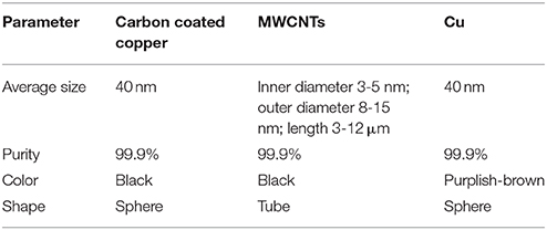
Table 1. The parameters of the nanoparticles.
In the present experiment, transmittance was used to evaluate the stability of three nanofluids. The transmittance was measured with a visible spectrophotometer (Model 721-100, Shanghai Quintessence Technology Instrument, Co., Ltd). This process is repeated three to four times, and the measured results are shown in Figure 1.
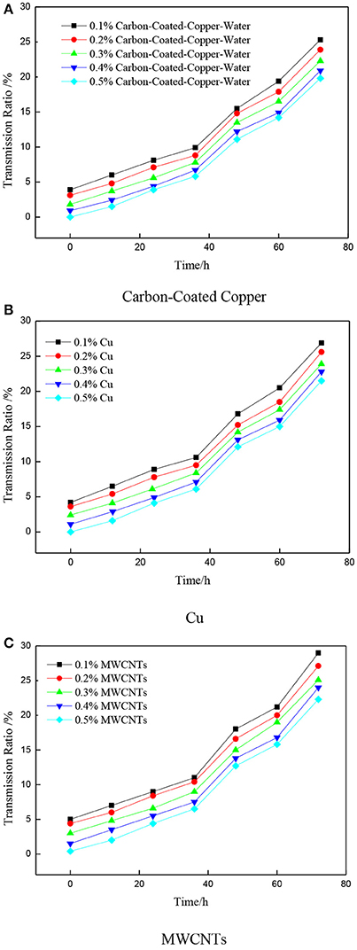
Figure 1. Stability of the nanofluids. (A) Carbon-Coated Copper. (B) Cu. (C) MWCNTs.
Figure 1 display that, as time increase, nanofluids gradually precipitate, because the more uniform distribution of nanofluids, the lower light transmittance we get. This nanofluids is difficult to deposit in the long term and is suitable for subsequent experimentation and application.
The experimental system depicted in Figure 2 consists of a heating control system, a data acquisition system, a heat radiation system, and an experimental section. The heating zone, which is 20 mm in diameter, is composed of a brass column with three heating pipes of 100 W inserted below. The upper surface is used to heat the center of the FPHP. K-type sheathed thermocouples, 1 mm in diameter, are used to measure and data acquisition, and is directly connected to the data collector. Above the heating zone are the pillars from the heating surface in distances of 5, 15, and 25 mm and two holes of 1 mm diameter, which will be used to measure the temperature of the center line of pillars. Two thermocouple measurements were averaged as the point value of the temperature. A thermocouple is placed at the center of the lower surface of the heat pipe to measure the maximum temperature of the heat pipe. Eleven thermocouples were placed within the radius of the heat pipe upper side with equal spacing, as shown in Figure 3A 120 × 120 × 45 mm aluminum heat sink was placed on top of the heat pipe. The top of the heating zone is equipped with 3 W fans for forced convection heat transfer.
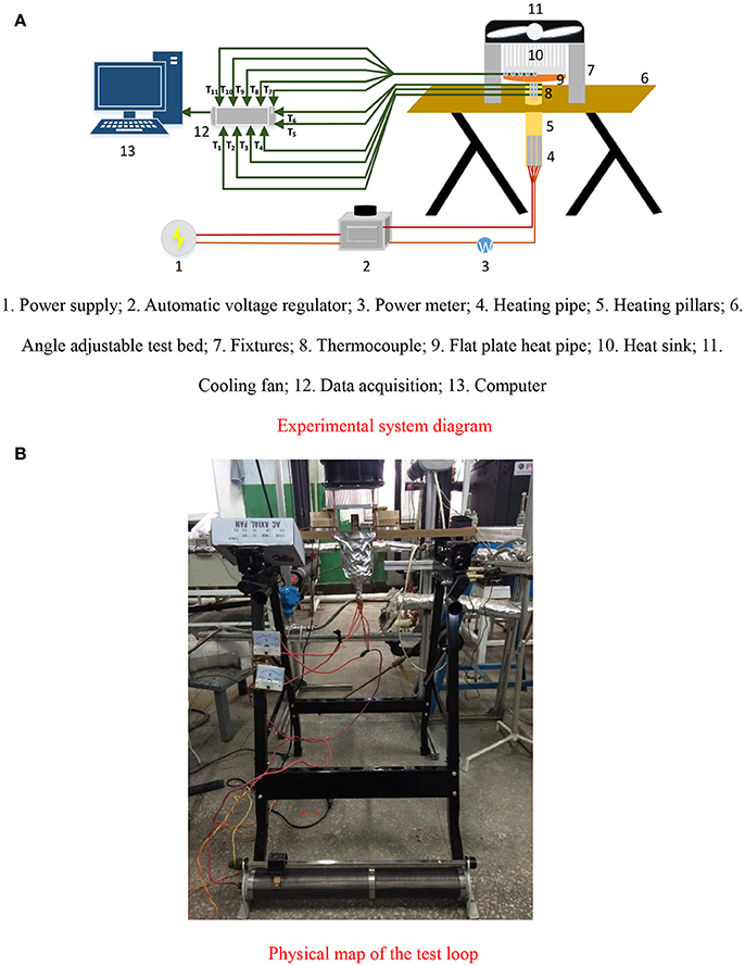
Figure 2. Schematic of the experimental system. 1. Power supply; 2. Automatic voltage regulator; 3. Power meter; 4. Heating pipe; 5. Heating pillars; 6. Angle adjustable test bed; 7. Fixtures; 8. Thermocouple; 9. Flat plate heat pipe; 10. Heat sink; 11. Cooling fan; 12. Data acquisition; 13. Computer. (A) Experimental system diagram. (B) Physical map of the test loop.
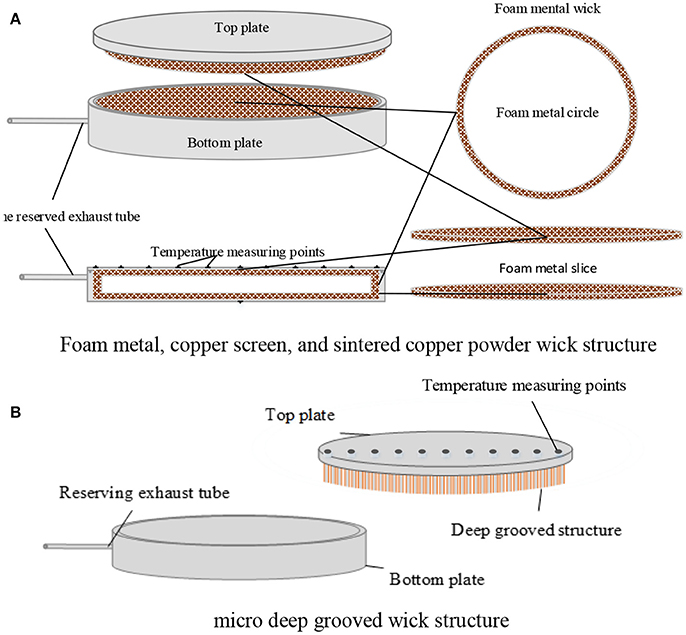
Figure 3. Flat heat pipe block diagram. (A) Foam metal, copper screen, and sintered copper powder wick structure. (B) Micro deep grooved wick structure.
Figure 3 shows the structure of the flat heat pipe and the distribution of temperature measurement points. In this experiment, to measure the surface temperature, the thermocouple and surface of heat pipe are fixed by SatlonD-3 and 606 catalysts. The thermocouple is in contact with the temperature measurement point at the surface, thereby reducing measurement error. Brass heating temperature is measured at the point of contact with the thermocouple and temperature measurement surface. Thermal grease was applied to reduce thermocouple thermal contact resistance. Insulation asbestos was placed around the heating element to insulate the process and lessen heat loss to the point of being negligible. Surface heating and cooling surfaces were evenly coated with thermal paste and fixing and pressing to reduce thermal contact resistance. Experimental data were collected by the data logger and transferred to a computer for monitoring and recording.
In this study, the working fluids included deionized water, Cu-water nanofluids, MWCNTs-water nanofluids, and carbon-coated copper-water nanofluids. Before the experiment, a vacuum pump with pressure of up to 6 × 10⁻² Pa was used to vacuum the flat heat pipe, then a syringe was used to pack the amounts of liquid. Five kinds of filling ratio with values of 0%, 8%, 20%, 40%, 60% and 100% were used. The flat heat pipe placed at angle θ were 0, 30, 60, and 90°, and the level of placement of the heat pipe was 0°. The heating power used is from 0-200 W. When the temperature on the surface of the heat pipe near the center in 10 min fluctuation was < 0.5°C, the heat transfer can be considered to have reached steady state.
The flat heat pipe working fluid flow was vapor-liquid two-phase flow, thus, the steam that the working fluid vaporization generated flowed to the condensing end of the heat pipe under slight pressure differential, when the flat end of the heat pipe is heated and evaporated. During the release of latent heat of vaporization and condensation, the working fluid condensed at the wick capillary returned from the condensing end to the evaporating end and achieved transfer of heat from the evaporating end to the condensing end. The normal operation of the flat heat pipe consisted of evaporation of the liquid, flow of steam, condensate, and steam condensate reflux composition. The operation must satisfy the following formula:
Where Δpc is the driving force of the working fluid circulating inside the heat pipe, which was used to overcome the vapor from the evaporator side pressure drop to the condensing end in flow Δp1, the pressure drop of reflux liquid from the condensing end to evaporating end Δpv, and pressure drop because of gravity Δpg. The largest of the capillary force of the foam metal can be obtained as (Peng Y. et al., 2013).
where σ is surface tension, α is a wetting angle, and deff is the effective aperture capillary force of the metal foam. In general, the deff is affected by the minimum diameter. In this experiment, because of the additional shortening of the liquid return path, the liquid reflux flow rate remained small and coupled with smaller pore size. The liquid flow Reynolds number was also small. The pressure drop of the liquid flow is calculated using Darcy's available (Hsieh et al., 2008):
where μ is the viscosity of the liquid, Δx is the fluid return path length, and K is the metal foam permeability coefficient. The literature shows that
In equilibrium, the mass flow rate of the liquid evaporates and the liquid supplements are the same
where is related with working fluid, called the working medium quality factor. is related to the wick and heat pipe structure. A flat heat pipe filled with working fluid should have high surface tension and latent heat of vaporization, because the former can provide a large capillary force, whereas the latter causes a certain amount of heat transfer fluid flow rate that requires less liquid reflux to reduce resistance. Lesser viscous liquid means higher quality of the working fluid.
The performance of the heat pipes can be produced by thermal conductivity and heat resistance. The thermal conductivity and heat resistance of the improved tablet wick was compared to the copper metal substrate. The heat transfer performance of the flat heat pipe was also analyzed. Flat plate heat pipe thermal conductivity is axially thermal. This parameter can be characterized through the temperature difference between the upper and lower surfaces of the heat pipe. Equivalent thermal resistance of heat conducting element is expressed as:
where Tmax is the maximum surface temperature of the heat pipe at the center of the lower surface temperature, Tavg is the average temperature on the higher surface of the heat pipe, and Q is the lower surface of the heat pipe with heated copper cylinder heat input. Heat flux density q (W/m2) can be calculated using the heat input. The heat flux formula is as follows:
The use of heat insulation asbestos pillars resulted in minimal heat, which can be ignored. However, to reduce the reading errors of power matter as well as avoid cooling errors, heat flux can be obtained by the Fourier equation (Ji et al., 2012):
where, k is the thermal conductivity of copper. The copper used in this experiment had a thermal conductivity of 401 W/(m·K). Through four temperature measurement points on the higher surface, the distribution of temperature on the surface on the plate can be obtained. Uniformity of temperature distribution reflects the average heat of the heat pipes. When the radial temperature gradient of the heat pipe is reduced, the temperature difference of the point on the surface is smaller, to that the surface temperature distribution is very uniform, thereby improving thermal uniformity.
The thermal resistance of the heat pipe is composed of two parts, pure phase changes thermal resistance and thermal resistance. To study the thermal conductivity of the filling heat pipe, the pure thermal resistance of the heat pipe should be measured when it is not filled. For comparison, the heat pipe and aluminum plate used in the same test must have the same sizes. After clamping fixtures, the power input heating tube is then connected. The experiment begins with a heating power of 10-200 W, and a power interval of 10 W. The temperature changes after each increase in heating power. When the respective measurement points are less than every 5 min, 0.1°C is reached, and is regarded as the steady state.
To enhance the precision of the experimental results, the system errors were analyzed and measurement uncertainty evaluated (Ghanbarpour et al., 2015). The uncertainty of the system mainly comes from the uncertainty of machining error, heat flux and thermal resistance. The computation formula of the uncertainty is as follows:
kcopper is the heat conductivity coefficient of copper, it is consult from the standard property sheet, the uncertainty can be ignored, The uncertainty of temperature is caused by the measurement error of thermocouple, Machining error was 2%, Equation (9) is used to calculate the uncertainty of heat flux; The thermal resistance calculation formula shows that the uncertainty of thermal resistance is depends on the temperature and heat flux, the uncertainty of thermal resistance can be calculated by Equation (10). The uncertainties and parameters of the instruments used in the experiment are listed in Table 1 while the uncertainty of the variables is presented in Table 2 and uncertainty of the experimental variables is shown in Table 3.
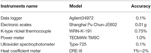
Table 2. Instrument parameters and uncertainty.
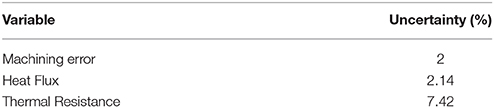
Table 3. Experimental variables and uncertainty.
Before the experiment, the heat balance of the experiment system should be discussed by calculated the deviation between input power Q and Ql, which Q is measured by power meter and Ql is calculated by the temperature nearby the surface of the heating copper column. Heat balance deviation can be expressed as follows (Zhao et al., 2016):
The heat balance deviation is got by computing and it is < 5%, thus the total power of the working medium can reach close to the set power of 100 W. This shows that the thermal insulation device performance is good, the heat loss of the experiment can be ignored.
Figure 4 shows the spread performance of four metal foam FPHPs with different working mediums. The experiment shows that when the heating power is set to 100 W, the heat pipe started sufficiently and achieve a lower temperature, so choose the heating power of 100 W to contrast the surface temperature distribution of FPHP. the mass fraction of all nanofluids is 0.5%, and the charging rate is 40%. As shown in the figure, when the heating power is 100 W, the maximum temperature difference of carbon-coated copper-water nanofluids, Cu-water nanofluids, MWCNT-water nanofluids and deionized water heat pipe on the surface is respectively 1.2, 2.8, 3.3, and 4.1°C, the top temperature of the copper plate is nonuniform distribution, the maximum temperature difference can reach 10.4°C, the FPHP filled of nanofluids is better than the deionized water heat pipe, and the FPHP is better than the copper plate. The carbon-coated copper-water nanofluids shows the best performance and has the smoothest curve compared to others, the temperature of the measurement points is low, Cu-water nanofluids heat pipe had the second-best performance. Meanwhile, compared with the previous two kinds of nanofluids, the spread performance of the multi-walled carbon nanotube-water heat pipe was poor. And the Cu nanofluids had larger fluid viscosity, and the viscosity had larger effect on the flow resistance of heat pipe system. From the surface temperature, the upper surface average temperature of carbon-coated-water heat pipe is 70.3°C, is 4.3°C lower than copper plate, that means the overall temperature of the heat pipe is lower than copper plate of the same size, also account for the cooling effect is better. Multi-walled carbon nanotubes-water nanofluid had both advantages of two nanofluids, high thermal conductivity and smaller viscosity of carbon nanotubes, and thus, the carbon-coated copper nanofluids heat pipe had the lowest thermal resistance.
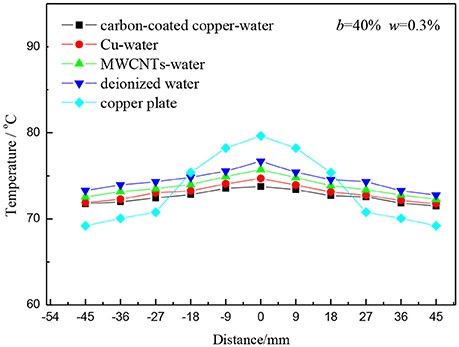
Figure 4. Surface temperature distributions of different medium FPHP.
Many factors affect heat transfer, including liquid ratio, capillary suction fluid wick structure and materials, heat pipe placed angle, internal working medium, heating power, etc. (Chen et al., 2013). Heat transfer performance evaluation was based on thermal resistance of heat pipe. When the thermal resistance is smaller, a better heat transfer performance can be obtained, and the main factors affecting it as well as the transient temperature can be analyzed from the following several aspects.
(1) Effect on thermal resistance of the working medium
Figure 6 shows thermal resistance under different powers of the four working mediums at 40% charging rate. The mass fraction of the three kinds of nanofluids is 0.5%, and the wick of the heat pipe is foam metal. As shown in Figure 5, for the four different working mediums, thermal resistance was larger heating power is small. Thermal resistance of the flat heat pipe decreased with the increase in heating power. This result can be attributed to the working medium inside the flat heat pipe producing heat absorption through the phase change with the gradual increase in heating power. Relative to the conduction and convection heat transfer, phase change heat transfer has the advantages of smaller heat transfer temperature difference and better heat transfer property. In addition, under the same heating power, flat heat pipe filled with nanofluids has smaller thermal resistance because the working medium added nanoparticles. The nanoparticles increased the surface area and thermal capacity, which in turn increased the coefficient of thermal conductivity of the working medium (Kumaresan et al., 2014). The collision and interaction between particles, water, water vapor, and metal surface, enhanced the heat transfer of the heat pipe. The carbon-coated copper nanofluids were chosen as the working medium, and the charging ratio is 40%. When the heating power is at 150 W and the thermal resistance is 0.1°C/W, the foam metal designs for the wick with nanofluids are chosen as working medium of flat pipe and had good axial heat conduction.
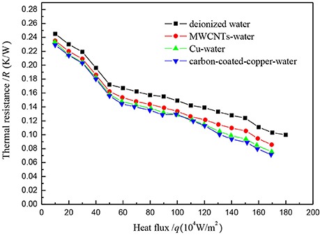
Figure 5. Change of thermal resistance of different medium of the FPHP.
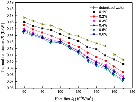
Figure 6. Change of thermal resistance of different mass fraction of the FPHP.
(2) Effect on thermal resistance of the mass fraction of the working medium
The heat transfer efficiency of carbon-coated copper is better than that of other heat pipe working mediums. In this paper, the mass fraction is studied by using carbon-coated copper-water nanofluids heat pipe. Figure 6 shows the thermal resistance of different mass fractions of carbon-coated copper-wanter nanofluids filled in foam metal FPHP. The heating power was 100 W, and the charging rate was 40%. With the increase of the mass fraction, the thermal resistance of foam mental FPHF is decreased first and then increased. In addition, the increase rate of the thermal conducted performance was reduced with the gradual increase of mass fraction. From the figure, the thermal resistance of deionized water heat pipe is 0.1391°C/W. The figure shows that the thermal resistance of carbon coated copper-water nanofluids heat pipe with the mass fraction of 0.5% is 0.1121°C/W. The increase of the mass fraction of the Nanoparticles caused high thermal efficiency, which could significantly improve the performance of the heat pipe. However, with the increase in mass fraction of the nanofluids, the viscosity of the working medium inside the heat pipe increased significantly and was averse to the heat transfer performance. According to the stability experiments of nanofluids introduced in section Introduction, precipitation will occur with the increase in mass fraction of nanofluids. Hence, a specific working medium concentration of nanoparticles that optimizes the heat transfer property exists. In the experiments, the thermal resistance of 0.5% of mass fraction minimum, when the mass fraction is 0.6%, heat pipe thermal resistance increased, that indicated the best quality score is between 0.5 and 0.6%.
(3) Effect on thermal resistance of the charging rate of working medium
The last group of experimental results show that the carbon-coated copper foam metal heat pipe has the lowest thermal resistance, and hence, carbon-coated copper-water nanofluids was chosen as working medium to discuss the effect of different charging rates of filling ratio on heat resistance. The mass fraction of carbon-coated copper nanofluids is 0.5%. Figure 7, under the low heating power, the flat plate heat pipe of 20% charging ratio has smaller thermal resistance than that of the other liquid ratio, and as the heating power increases gradually, the thermal resistance of all charging ratio is reduced. That is because with the heating power increasing, the boiling liquid film thickness at phase interface inside the heat pipe will reduce gradually, and the phase change thermal resistance will decrease until it reaches a certain value. In this experiment, 40% liquid filling ratio of the heat pipe shows good heat transfer effect during the high heating power, and over a wide range of heating power, it has maintained stable thermal resistance. When the heating power is at 150 W, the heat pipe carried the heat flux density of around 47.77 kW/m2, and the heat pipe boil dry phenomenon did not happen. When the heating power was adjusted from 150 W to 160 W, the measured temperature from the three thermocouples inside the copper heating column reached more than 30°C in a matter of seconds. This phenomenon shows that flat heat pipe internal dry phenomenon has occurred, and the heat transfer is deteriorating.
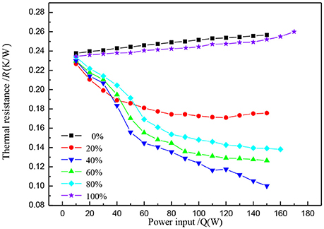
Figure 7. Thermal resistance variation with the change in heat input of the different mediums of FPHP.
(4) Effect on thermal resistance of the tilt angle
Figure 8 shows the effect of the tilt angle of the carbon-coated copper nanofluids FPHP with mass fraction of 0.5% and charging rate of 40%. When the heating power is small and the inclination angles are 60 and 90°, thermal resistance value slowly decreased along with the increase in heating power. When the heat pipe is in a horizontal position or the tilt angle is small, thermal resistance rapidly decreased with the increase of heating power. When the heating power is within the range of 40-100 W, the thermal resistance of the flat plate heat pipe is at a minimum, whereas when the FPHP is upright, the resistance increased. However, with the further increase of the heating power, the heat resistance of the four angle conditions of heat pipe gradually converged, and when the heating power is nearly 150 W, the heat transfer deterioration did not occur.
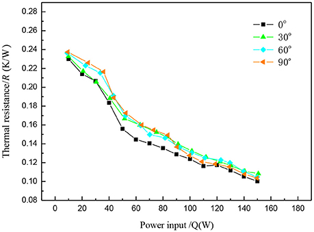
Figure 8. Effect of the placement angle on the thermal resistance.
(5) Effect on thermal resistance of the wick structure
As a key part of the heat pipe, the wick has three main functions: as a working medium flow channel, as a working medium of the phase interface, and as provider of backflow capillary force for the working medium. The effective pore radius of the wick should be smaller to guarantee the backflow power of the working medium. The wick should also have sufficient permeability to reduce the pressure drop of the backflow (Li et al., 2016). Wick thermal resistance should be smaller to reduce radial thermal resistance.
The wick is an important part of heat pipe. The most common wicks include screen, sintering, and groove type wicks. The performance of the grooved structure applied to FPHP is stable and does not require sintering. It can also conduct heat dissipation through the fin in the steam chamber. The experiment perfected and proposed a micro deep triangle-grooved wick, which involved cutting the copper board through three directions at an angle of 60°. The porosity of this kind of wick is larger, leading to a tri-prism unit structure with smaller pore diameter. The steam chamber increases the condensation area, which is good for steam condensation. Porosity and capillary force are increased by reducing the width of the pore and increasing the quality of porosity. The edge of the micro prism of groove structure with smaller angle has better infiltration of liquid than that of Right Angle. Figure 9 shows the improvement of micro deep triangle-grooved wick and micro deep rectangle-grooved wick structure.
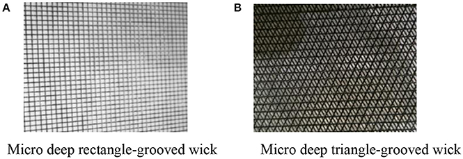
Figure 9. Traditional and novel micro deep grooved wick. (A) Micro deep rectangle-grooved wick. (B) Micro deep triangle-grooved wick.
The porosity of copper screen wick and sintered copper wick can be calculated:
θ is the porosity of the wick, Vpore is the velocity of the internal porosity of the wick, Vtotal is the whole velocity of the wick. Vpore = Vtotal− Vcopper, the Vtotal is calculated by Equation (14):
Among them, D is the external diameter of the FPHP, δ is the thickness of the wick, ξ is the thickness of the pipe, mcopper is the mass of the wick.
In this experiment, all the heat pipe is of the same size, and the shape is disc, its diameter is 90 mm, the thickness of the plate is 9 mm, the thickness of the tube wall on the top and lateral is 2 mm, the thickness of the lower tube wall is 1.5 mm. The diameter of copper tube connected with the pumping air hole is 3 mm, since the cut-off point is very close to the heat pipe, its influence can be neglected. Several parameters of the wick as the following Tables 4, 5:
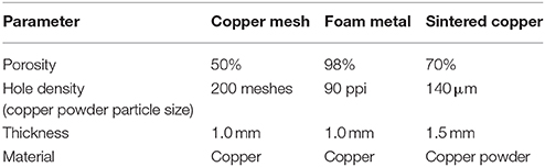
Table 4. The parameters of the sintering wick.
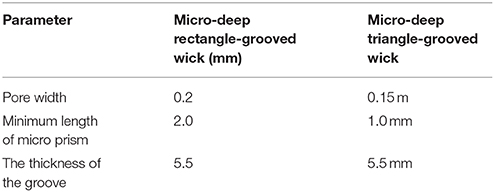
Table 5. The parameters of the micro-deep grooved wick.
Figure 10 shows the heat pipe using carbon-coated copper nanofluids as working medium, which had a mass fraction of 0.5%, and filling rate of 40% as applied to copper screen wick, sintered copper wick, foam metal wick, and two kinds of micro grooved wick of flat heat pipe. Under low heat input, when the input power is 30 W, the micro deep rectangle-grooved wick heat pipe had the lowest thermal resistance of 0.1897°C/W, and the micro deep rectangle-grooved wick heat pipe had the second lowest thermal resistance of 0.1913°C/W. The thermal resistance of the sintered copper heat pipe and foam metal was lower than that of the copper mesh heat pipe. When the heat input was increased, the change of heat transfer performance of the micro deep rectangle-grooved wick heat pipe was unobviously, the minimum thermal resistance is 0.1674°C/W. However, with the increase of heat flux density, the thermal resistance of micro deep triangle-grooved wick is only 0.1460°C/W, and it is obviously lower than the traditional heat pipe. Relative to the structure of the three wicks with larger cavity, the variations in thermal resistance of the sintered copper wick heat pipe is smaller compared to others, and the heat transfer performance of the foam metal and copper network wick further increased, causing the thermal resistance of the metal foam FPHP to be at the minimum. This result can be attributed to the groove type heat pipe having upper and lower connections of miniature frame column in its chamber; the rib can conduct axial heat directly. Because of the smaller internal cavity, the heat pipe can be used under low heat flux, and can easily reach a stable state; however, it also brings forward the boiling limit (Peng H. et al., 2013). The micro deep triangle-grooved wick heat pipe increased the space inside the heat pipe, had better porosity, and reduced the volume of the frame column. Thus, the thermal performance under low heat flow density is better than the traditional type. With better porosity, the heat pipe could withstand higher heat flux, and under low heat flux density, the heat pipe also had lower thermal resistance. The nanofluids can achieve good results in the appropriate aperture of the deep groove of the heat pipe, which strengthened the heat exchange through the fins. Relative to the cavity structure, the heat pipe with micro deep grooved wick remained stable within a certain range of heat flux. The size of the aperture of the bronze lotion wick was larger, making the effective radius bigger and the capillary force smaller, and causing the start-up temperature of heat pipe demand to become higher. The heat transfer performance is poor under low heat input. The sintered copper has a smaller aperture, which can effectively provide better capillary force. The small aperture will cause a blocking phenomenon when the working medium used is colloid containing nanoparticles. The small aperture will also lead to reduced permeability of the working medium, which increased the backflow resistance. Under high heat input, it cannot further enhance the heat transfer effect. Nanofluids in metal foam wick with appropriate aperture will not easily cause a blocking phenomenon, and can provide good capillary force, which results in high permeability. Therefore, the FPHP of metal foam wick has good heat transfer properties.
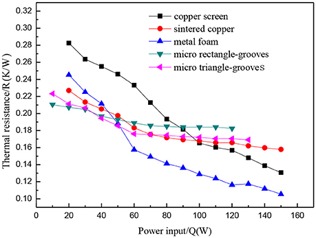
Figure 10. Effect on the thermal resistance of different wick structures.
This paper studied the heat transfer characteristics of metal foam wick and combined the 90 ppi of metal foam wick with Cu, MWCNT and carbon nanometer copper nanoparticles, and deionized water as working medium. Based on the experiment analysis of the two aspects of spread performance and heat transfer resistance, the following conclusions can be reached:
(1) The surface temperature distribution of the heat pipe. When the heating power is 100 W, the maximum temperature difference of carbon-coated copper-water nanofluids, cu-water nanofluids, multi-walled carbon nanotubes-water nanofluids and deionized water heat pipe on the surface is 1.2, 2.8, 3.3, and 4.1°C respectively.
(2) The filling ratio had a more significant effect on the FPHP. The paper explores carbon-coated copper water nanofluids and the thermal change that occurs inside the heat pipe as the working fluid caused the different filling ratios. The results of the study show that the metal foam FPHP has the best performance at a filling rate of 40%.
(3) When the heat pipe is placed at an angle of 0°, the heat pipe has the lowest thermal resistance, when the tilt angle is 90°, the thermal resistance is < 0.05°C/W, that means the heat pipe is stable.
(4) The heat transfer properties of the foam metal heat pipe had better cooling effect as compared with that of sintered and copper mesh.
BS: Provided experimental design ideas and overall project planning. CP: Carried on experiment, data processing and analysis. DY: Carried on experiment. HL: Digital signal process.
The authors declare that the research was conducted in the absence of any commercial or financial relationships that could be construed as a potential conflict of interest.
This study was supported by the Program for Science and technology development projects of Jilin province (20160101282JC, 20160520032JH, 20170101123JC) and National Natural Science Foundation of China (No. 51406031).
Aly, W. I. A., Elbalshouny, M. A., El-Hameed, H. M. A., and Fatouh, M. (2016). Thermal performance evaluation of a helically-micro-grooved heat pipe working with water and aqueous Al2O3, nanofluid at different inclination angle and filling ratio. Appl. Thermal Eng. 110, 1294–1304. doi: 10.1016/j.applthermaleng.2016.08.130
Bhullar, B. S., Gangacharyulu, D., and Das, S. K. (2016a). Temporal deterioration in thermal performance of screen mesh wick straight heat pipe using surfactant free aqueous nanofluids. Heat Mass Transf. 53, 241–251. doi: 10.1007/s00231-016-1785-6
Bhullar, B. S., Gangacharyulu, D., and Das, S. K. (2016b). Augmented thermal performance of straight heat pipe employing annular screen mesh wick and surfactant free stable aqueous nanofluids. Heat Transf. Eng. 38, 217–226. doi: 10.1080/01457632.2016.1177418
Chen, Y.-T., Kang, S.-W., Hung, Y.-H., Huang, C.-H., and Chien, K.-C. (2013). Feasibility study of an aluminum vapor chamber with radial grooved and sintered powders wick structures. Appl. Thermal Eng. 51, 864–870. doi: 10.1016/j.applthermaleng.2012.10.035
Ghanbarpour, M., Nikkam, N., Khodabandeh, R., and Toprak, M. S. (2015). Improvement of heat transfer characteristics of cylindrical heat pipe by using SiC nanofluids. Appl. Thermal Eng. 90, 127–135. doi: 10.1016/j.applthermaleng.2015.07.004
Haddad, Z., Abid, C., Oztop, H. F., and Mataoui, A. (2014). A review on how the researchers prepare their nanofluids. Int. J. Thermal Sci. 76, 168–189. doi: 10.1016/j.ijthermalsci.2013.08.010
Hajian, R., Layeghi, M., and Sani, K. A. (2012). Experimental study of nanofluid effects on the thermal performance with response time of heat pipe. Energy Convers. Manage. 56, 63–68. doi: 10.1016/j.enconman.2011.11.010
Hassan, H., and Harmand, S. (2015). Study of the parameters and characteristics of flat heat pipe with nanofluids subjected to periodic heat load on its performance. Int. J. Thermal Sci. 97, 126–142. doi: 10.1016/j.ijthermalsci.2015.06.009
Hongchuan, L., Xianbing, J., Xiaohuan, Z., Wolong, Y., and Jinliang, X. (2015). Study on heat transfer properties of flat heat pipe with conical capillary wicks. J. Mech. Eng. 51:132. doi: 10.3901/JME.2015.24.132
Hsieh, S.-S., Lee, R.-Y., Shyu, J.-C., and Chen, S.-W. (2008). Thermal performance of flat vapor chamber heat spreader. Energy Convers. Manage. 49, 1774–1784. doi: 10.1016/j.enconman.2007.10.024
Hsieh, S. S., and Yang, Y. R. (2013). Design, fabrication and performance tests for a polymer-based flexible flat heat pipe. Energy Convers. Manage. 70, 10–19. doi: 10.1016/j.enconman.2013.02.011
Ji, X., Xu, J., and Abanda, A. M. (2012). Copper foam based vapor chamber for high heat flux dissipation. Exp. Thermal Fluid Sci. 40, 93–102. doi: 10.1016/j.expthermflusci.2012.02.004
Kim, H. J., Lee, S. H., Kim, S. B., and Jang, S. P. (2016). The effect of nanoparticle shape on the thermal resistance of a flat-plate heat pipe using acetone-based Al2O3 nanofluids. Int. J. Heat Mass Transf. 92, 572–577. doi: 10.1016/j.ijheatmasstransfer.2015.09.013
Kumaresan, G., Venkatachalapathy, S., and Asirvatham, L. G. (2014). Experimental investigation on enhancement in thermal characteristics of sintered wick heat pipe using CuO nanofluids. Int. J. Heat Mass Transf. 72, 507–516. doi: 10.1016/j.ijheatmasstransfer.2014.01.029
Lefèvre, F., Conrardy, J. B., Raynaud, M., and Bonjour, J. (2012). Experimental investigations of flat plate heat pipes with screen meshes or grooves covered with screen meshes as capillary structure. Appl. Thermal Eng. 37, 95–102. doi: 10.1016/j.applthermaleng.2011.11.022
Li, H. Y., Chiang, M. H., Lee, C. I., and Yang, W.-J. (2010). Thermal performance of plate-fin vapor chamber heat sinks. Int. Commun. Heat Mass Transf. 37, 731–738. doi: 10.1016/j.icheatmasstransfer.2010.05.015
Li, Y., Li, Z., Chen, C., Yan, Y., Zeng, Z., and Li, B. (2016). Thermal responses of heat pipes with different wick structures under variable centrifugal accelerations. Appl. Thermal Eng. 96, 352–363. doi: 10.1016/j.applthermaleng.2015.11.016
Littwin, D. A., and Mccurley, J. (1981). Heat pipe waste heat recovery boilers. J. Heat Recovery Syst. 1, 339–348. doi: 10.1016/0198-7593(81)90045-X
Mehrali, M., Sadeghinezhad, E., Azizian, R., Akhiani, A. R., Latibari, S. T., Mehrali, M., Simon, H., et al. (2016). Effect of nitrogen-doped graphene nanofluid on the thermal performance of the grooved copper heat pipe. Energy Convers. Manage. 118, 459–473. doi: 10.1016/j.enconman.2016.04.028
Mizuta, K., Saito, Y., Goshima, T., and Tsutsui, T. (2015). Measurement of coolant in a flat heat pipe using neutron radiography. Phys. Procedia 69, 556–563. doi: 10.1016/j.phpro.2015.07.079
Moraveji, M. K., and Razvarz, S. (2012). Experimental investigation of aluminum oxide nanofluid on heat pipe thermal performance. Int. Commun. Heat Mass Transf. 39, 1444–1448. doi: 10.1016/j.icheatmasstransfer.2012.07.024
Nazari, M. A., Ghasempour, R., Ahmadi, M. H., Heydarian, G., and Shafii, M. B. (2018). Experimental investigation of graphene oxide nanofluid on heat transfer enhancement of pulsating heat pipe. Int. Commun. Heat Mass Transf. 91, 90–94. doi: 10.1016/j.icheatmasstransfer.2017.12.006
Ozsoy, A., and Corumlu, V. (2018). Thermal performance of a thermosyphon heat pipe evacuated tube solar collector using silver-water nanofluid for commercial applications. Renewable Energy 122, 26–34. doi: 10.1016/j.renene.2018.01.031
Peng, H., Li, J., and Ling, X. (2013). Study on heat transfer performance of an aluminum flat plate heat pipe with fins in vapor chamber. Energy Convers. Manage. 74, 44–50. doi: 10.1016/j.enconman.2013.05.004
Peng, Y., Liu, W., Wang, N., Tian, Y., and Chen, X. (2013). A novel wick structure of vapor chamber based on the fractal architecture of leaf vein. Int. J. Heat Mass Transf. 63, 120–133. doi: 10.1016/j.ijheatmasstransfer.2013.02.021
Sadeghinezhad, E., Mehrali, M., Rosen, M. A., Akhiani, A. R., Latibari, S. T., Mehrali, M., et al. (2016). Experimental investigation of the effect of graphene nanofluids on heat pipe thermal performance. Appl.Thermal Eng. 100, 775–787. doi: 10.1016/j.applthermaleng.2016.02.071
Saleh, R., Putra, N., Prakoso, S. P., and Septiadi, W. N. (2013). Experimental investigation of thermal conductivity and heat pipe thermal performance of ZnO nanofluids. Int. J. Thermal Sci. 63, 125–132. doi: 10.1016/j.ijthermalsci.2012.07.011
Sarafraz, M. M., and Hormozi, F. (2014). Experimental study on the thermal performance and efficiency of a copper made thermosyphon heat pipe charged with alumina-glycol based nanofluids. Powder Technol. 266, 378–387. doi: 10.1016/j.powtec.2014.06.053
Su, X., Zhang, M., Han, W., and Guo, X. (2016). Experimental study on the heat transfer performance of an oscillating heat pipe with self-rewetting nanofluid. Int. J. Heat Mass Transf. 100, 378–385. doi: 10.1016/j.ijheatmasstransfer.2016.04.094
Tharayil, T., Asirvatham, L. G., Ravindran, V., and Wongwises, S. (2016). Thermal performance of miniature loop heat pipe with graphene–water nanofluid. Int. J. Heat Mass Transf. 93, 957–968. doi: 10.1016/j.ijheatmasstransfer.2015.11.011
Tsai, M. C., Kang, S. W., and Paiva, K. V. D. (2013). Experimental studies of thermal resistance in a vapor chamber heat spreader. Appl. Thermal Eng. 56, 38–44. doi: 10.1016/j.applthermaleng.2013.02.034
Wu, Q., Xu, R., Wang, R., and Li, Y. (2016). Effect of C60 nanofluid on the thermal performance of a flat-plate pulsating heat pipe. Int. J. Heat Mass Transf. 100, 892–898. doi: 10.1016/j.ijheatmasstransfer.2016.05.008
Wusiman, K., Jeong, H., Tulugan, K., Afrianto, H., and Chung, H. (2013). Thermal performance of multi-walled carbon nanotubes (MWCNTs) in aqueous suspensions with surfactants SDBS and SDS. Int. Commun. Heat Mass Transf. 41, 28–33. doi: 10.1016/j.icheatmasstransfer.2012.12.002
Zhao, N., Yang, J., Li, H., Zhang, Z., and Li, S. (2016). Numerical investigations of laminar heat transfer and flow performance of Al2O3-water nanofluids in a flat tube. Int. J. Heat Mass Transf. 92, 268–282. doi: 10.1016/j.ijheatmasstransfer.2015.08.098
Zhou, W., Ling, W., Duan, L., Hui, K. S., and Hui, K. N. (2016). Development and tests of loop heat pipe with multi-layer metal foams as wick structure. Appl. Thermal Eng. 94, 324–330. doi: 10.1016/j.applthermaleng.2015.10.085
Zou, H., Wang, W., Zhang, G., Qin, F., Tian, C., and Yan, Y. (2016). Experimental investigation on an integrated thermal management system with heat pipe heat exchanger for electric vehicle. Energy Conver.Manage. 118, 88–95. doi: 10.1016/j.enconman.2016.03.066
Ae, Wick surface area of the evaporator (m2)
Al, Cross-sectional area of the wick perpendicular to the liquid flow direction (m2)
dp, Pore diameter of metallic foam (m)
deff, Effective pore diameter of the wick (m)
ΔP, Pressure drop (Pa)
Δx, Distance for the liquid flow path (m)
Hfg, Latent heat of evaporation (J/kg)
K, Permeability (m2)
N, Combined parameter for working liquid (W/m2)
G, Combined parameter for the porous wick
k, Thermal conductivity of copper (W/(m·K))
ppi, Number of pores per inch
p, Pressure (Pa)
q, Heat flux (W/m2)
q̀, Evaporator heat flux (W/m2)
Q, Effective heating power (J)
R, Thermal resistance (K/W)
T, Temperature (K or °C)
U, Liquid surface velocity (m/s)
B, filling ratio
W, mass fraction
Greek symbols
α, wetting angle
ε, Coefficient of thermal equilibrium
θ, porosity
σ, liquid surface tension (N/m)
μ, viscosity (kg/(m·s))
ρ, density (kg/m3)
δ, thickness of the wick
ξ, thickness of the tube wall
Subscripts
l, liquid
v, vapor phase
c, capillary
eff, effective
g, gravity
avg, average
max, maximum
min, minimum
Keywords: metal foam, nanofluids, capillary wick, flat heat pipe, thermal resistance
Citation: Sun B, Peng C, Yang D and Li H (2018) Effect of the Wick and the Working Medium on the Thermal Resistance of FPHP. Front. Energy Res. 6:37. doi: 10.3389/fenrg.2018.00037
Received: 28 February 2018; Accepted: 19 April 2018;
Published: 24 July 2018.
Edited by:
Zhaoming Meng, Harbin Engineering University, ChinaReviewed by:
Han Zhang, Karlsruher Institut für Technologie, GermanyCopyright © 2018 Sun, Peng, Yang and Li. This is an open-access article distributed under the terms of the Creative Commons Attribution License (CC BY). The use, distribution or reproduction in other forums is permitted, provided the original author(s) and the copyright owner(s) are credited and that the original publication in this journal is cited, in accordance with accepted academic practice. No use, distribution or reproduction is permitted which does not comply with these terms.
*Correspondence: Bin Sun, c3VuYmluQG5lZXB1LmVkdS5jbg==
Disclaimer: All claims expressed in this article are solely those of the authors and do not necessarily represent those of their affiliated organizations, or those of the publisher, the editors and the reviewers. Any product that may be evaluated in this article or claim that may be made by its manufacturer is not guaranteed or endorsed by the publisher.
Research integrity at Frontiers
Learn more about the work of our research integrity team to safeguard the quality of each article we publish.