 Xiaofeng Guo*
 Alain Pascal Goumba
- ESIEE Paris, Université Paris Est, Noisy Le Grand, France
Process intensification (PI) technologies represent all approaches leading to size reduction and efficiency improvement of process equipment. Thermal energy storage (TES) systems are key elements in renewable and recovery thermal energy deployments, and their performance can benefit from PI principles. This study covers a brief analysis and state of the art of several PI technologies applied to TES systems. All sensible, latent, and thermochemical storage systems are covered. Two surface-to-volume ratios closely related to component size and system performance are first analyzed. They theoretically show how PI principles may inspire the performance enhancement of TES systems. Then, a brief synthesis on successful PI applications in sensible, latent, and thermochemical storages is given. Their approaches mainly consist of thermal stratification preservation, modular design, heat and mass transfer enhancement, as well as material properties modification. Finally, potential TES system improvement directions based on PI principles are recommended.
Introduction
Waste energy recovery and renewable energy development in the building sector reduce fossil energy dependence and its environmental impact. However, these energy sources are either far away from residential district or intermittent in time (Goumba et al., 2017). The distance in space and time between sustainable sources and building energy demands requires thermal energy storage (TES) systems. Particularly, in district heating networks, a well-dimensioned TES system could optimize energy use. Since TES can store surplus energy production and release it later on demand, the fraction of sustainable energy in total annual consumption can be as high as 100% without system over-dimensioning. In general, a large thermal storage is needed in a central installation; Complementary local buffer storage close to end users can be used to smooth load fluctuation. In some situations, movable storage can be used to cover the spatial distance too. The positioning of TES in a high-renewable-injected district heating network is shown in Figure 1.
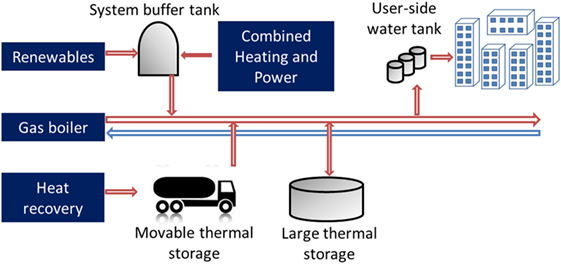
Figure 1. Different thermal energy storage systems in a multisource heat network.
Low-temperature TES with a storage temperature ranging from 30 to 70°C is expected to be extensively applied to modern energy networks. According to Lund et al. (2014), the fourth generation of district heating should be generalized in the horizon of 2020–2050. In such an energy delivering system, sustainable buildings that require low-energy space heating and hot water system will be connected to low-temperature smart thermal grids. Steam (first generation) or pressurized hot water around 100°C (second and third generation) will gradually disappear from sustainable cities due to their inefficiency feature. The concept of “thermal smart-grid,” similar to “power smart-grid,” needs flexible and efficient thermal storage modules.
This article deals with the performance enhancement of low-temperature TES that could be potentially applied to future centralized or decentralized heating networks with multisource heat injection. We introduce various principles of process intensification (PI), extensively used in the field process engineering, to the function improvement of sensible, latent, and thermochemical TES systems.
TES and PI Principles
Different TES Systems
Different TES systems, from hourly to seasonal storage, from centralized installation to small-size equipment, have been extensively used or underdevelopment. The most known TES system is perhaps hot water tanks sizing around a 100 L, generally installed in individual homes. Some others are on a greater scale, such as storage in aquifer (ATES) or borehole (BTES). Advanced TES systems using phase change materials (PCMs) or thermochemical techniques have also been studied extensively. Each of these systems has its own pros and cons, which can be evaluated by different criteria. For any of the above storage technologies, a TES should be the following:
(i) Reliable and flexible: energy could be retrieved with sufficient quantity (discharging power) whenever demanded;
(ii) Efficient: charged energy should be recovered with the lowest heat loss;
(iii) Compact: enough energy should be stored in an acceptable volume and mass.
In the case of central storage application, systems with higher capacity and small size may reduce the construction investment; whereas for the case of individual installation, compact systems could help saving space occupation. Moreover, compact TES could be prefabricated before installation, extensively reducing costs due to on-site intervention.
Scale Effect
In general, high-capacity TES requires large storage volume, which in turn results in low-energy loss through insulation. This could be explained from Eq. 1, in which heat loss rate could be explained with insulation UA number (heat loss coefficient) times the temperature difference between storage and ambiance. And stored thermal energy Qsto for a sensible TES could be obtained by multiplying the density and the heat capacity of storage medium, storage volume as well as the temperature difference between initial temperature (here supposed to be the same as ambiance) and storage temperature. The specific energy loss rate ε could be expressed by the following equation:
We can observe that the specific energy loss rate ε depends highly on the ratio Aouter/Vsto, representing the insulation surface area per storage volume. Since this ratio decreases with larger TES (Hadorn, 2008), this means low-specific energy loss rate for large-scale pit TES or ATES systems compared with small tank TES.
Another important issue is the energy charging and discharging rate, especially for indirect storage systems. The specific charging rate is given in Eq. 2, where Ainner represents inner heat exchange surface between heat transfer fluid (HTF) and storage medium. The (inner heat transfer area)/(storage volume) ratio Ainner/Vsto directly influences the charging rate in a positive proportional manner (H is the heat exchange coefficient between HTF and water).
In conclusion, perfect TES systems are expected to hold high-specific charging or discharging rate γ to be flexible and low-specific energy loss rate ε for better energy conservation.
Process Intensification
Process intensification technologies are mainly characterized by at least one of the following three elements: (i) enhanced heat and mass transfer, (ii) size reduction, and (iii) modular design. First, enhancement in heat and mass transfer, mainly through higher (internal heat transfer surface)/(storage volume) ratio in PI equipment than conventional ones, gives rise to better performance at both component level and system level. Then, with size-reduced equipment, precise process control and optimal energy flux management could be realized with ease. Finally, modular design transforms the design routine of process/thermal engineers from scaling-up to numbering-up. Faced with capacity increase, equipment parallelization is in most cases much easier than totally re-dimensioning a system.
Conventional TES systems and modular TES with PI benefits are shown in Figure 2. TES systems may take advantage of employing PI technologies from several aspects. First of all, latent heat storage systems using PCMs may achieve high charging/discharging power, thanks to heat and mass transfer enhancement. Then, modular arrangement of TES system makes thermal smart-grid possible. In existing thermal energy networks, the integration of renewable energy with high-intermittent characters requires the TES system to be highly flexible. With fixed size storage system, dealing with varied input/output has always been a tough task. However, with modular TES system, this becomes a simple issue of numbering-up process.
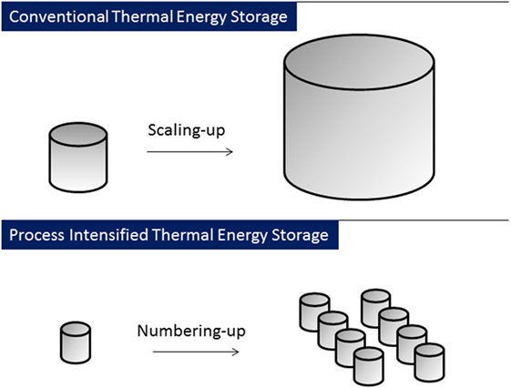
Figure 2. Thermal energy storage system using process intensification technologies hold advantages such as size reduction, modular integration facility, and better performances.
This study tries to show how PI technologies can be used in TES improvement. Technical obstacles of various TES, as summarized in Figure 3, could be tackled, thanks to the PI application. For example, in seasonal TES by PCM, a critical challenge is the control of subcooling during the phase change process. This challenge may be resolved by precise temperature control, thanks to high A/V ratio in an intensified device. In a similar manner, sensible and sorption systems can also benefit from PI techniques.
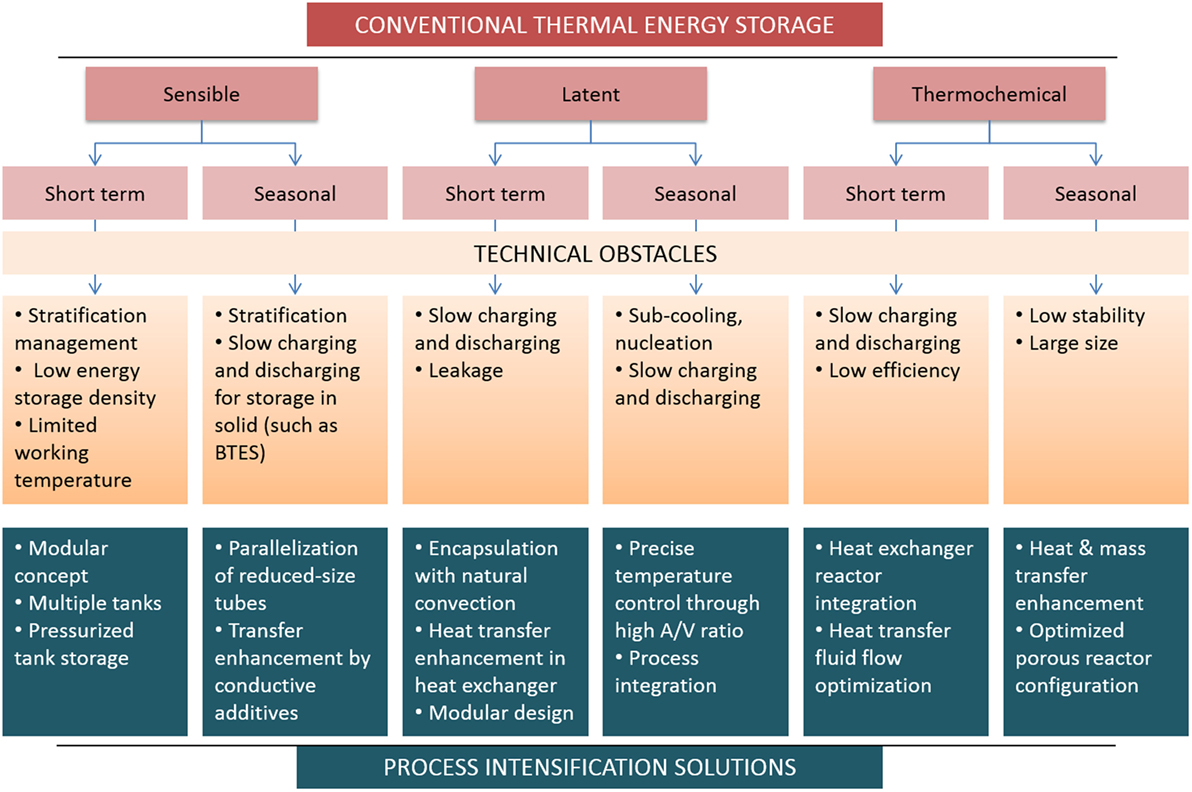
Figure 3. Different thermal energy storage systems and their technical obstacles, which might be tackled using process intensification principles.
Successful PI Applications in TES
Stratification in Sensible TES
The phenomenon of thermal stratification is defined by layered temperature differentiation in a vertical tank due to buoyancy-driven natural convection. A well-stratified heat storage tank maintains a thin layer that separates the cold region and hot region, and this layer is named thermocline. Water temperature holds a high gradient exclusively in this layer. Three influential heat transfer mechanisms are as follows: (i) heat diffusion between neighboring layers, including that within the fluid and that via tank border; (ii) forced convection by fluid mixing due to flow recirculation or local turbulence; and (iii) buoyancy-driven natural convection. To intensify thermal stratification, only the last heat transfer should be enhanced, and all the rest should be minimized.
Technologies aiming to minimize turbulence are generally used, both in small-size reservoirs and in large systems. For tanks, low-flow inlet is generally recommended, which gives less hydraulic turbulence. This can be realized by using inlet diffuser as shown in Figure 4. In other cases where the inlet flow rate should be maintained at a high level, special dispositive could be used to take advantage of buoyancy-driven flow. These devices include density-dependent valves and thermal diodes. For large installations, special inlet manifolds with adjustable inlet position according to the vertical temperature profile are generally useful to guarantee the usability of energy. The mechanism of thermal stratification and different devices used to intensify it are shown in Figure 4.
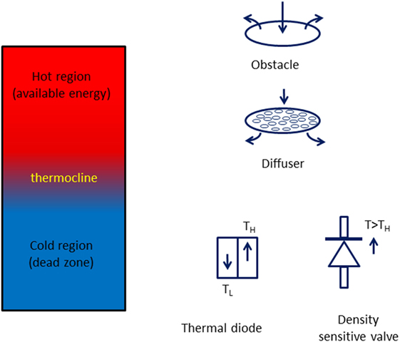
Figure 4. Thermal stratification phenomenon and its enhancement by inlet obstacles, diffusers, valves, and thermal diodes.
Inlet Obstacle and Diffuser
Obstacles placed against cold-side inlet are favorable to stratification. As studied by Altuntop et al. (2005), cone- and ring-shaped obstacles decrease the influence of inlet turbulence on stratification during hot water utilization. They investigated by simulation a tank with a height of 1.5 m and a diameter of 1 m, connected directly to a low-flow solar panel. With an initial temperature of 47°C, hot water is consumed with a speed of 1 m/s during 30 min. Meanwhile, cold water of the same flow rate is introduced at the inlet. Thanks to obstacles, inside hot water is kept stratified with a difference of 20°C between the upper (50°C) and lower (30°C) temperatures. In contrast to this, the same scenario conducted to the tank without inlet obstacle is almost fully mixed. Results indicate that temperatures only differ by 1°C from 43 to 44°C.
The effect of perforated diffusers on thermocline development is significant under certain conditions. According to the study by Zurigat et al. (1988), with Richardson numbers lower than 5, a diffuser starts to play an important role in the stratification. Moreover, perforated diffuser with a solid center gives better stratification than that with completely perforated diffuser or completely solid one. More sophisticated diffusers under the same principle are available too such as that studied by Mehling et al. (2003).
Brown and Lai (2011) designed and tested experimentally an inlet manifold made by rolled nylon screen. A tank with a volume of 315 L and aspect ratio of H/d = 2 is charged by hot water with different temperature (from 30 to 61°C) and flow rates (from 5.73 to 143.85 mL/s). The temperature gradient in the thermocline region is used to evaluate the stratification degree, with respect to Richardson and Péclet numbers. From their results, a satisfactory thermocline is maintained even in inertia-dominated flow (Richardson number as low as 0.615), thanks to the inlet porous manifold.
Density Sensible Valve
Circulating water only at the right temperature also helps maintaining thermocline. Smith et al. (2010) devised a density sensitive valve by using a float whose density is the same as that of water at objective action temperature. The float rises when the temperature of water is lower than the critical value, and this gives a closed state to the valve. Otherwise, the float descends, and the valve remains open.
Thermal Diodes
Thermal diodes are passive devices that enhance natural convection by promoting buoyancy-driven hot water upward flow and cold water descent. Devore et al. (2013) incorporated thermal diodes in partitioned water tanks used in solar thermal systems. According to their simulation and experimental results, two separated partitions with four thermal diodes placed in each segment show the best annual performance.
Aspect Ratio
The height-and-diameter ratio H/d has effects on both thermal stratification and heat loss. On the one hand, from the point of view of heat loss, the best H/d ratio is around 1, corresponding to a minimum insulation surface–volume ratio Aouter/Vsto. On the other hand, higher H/d favors thermal stratification as natural convection due to temperature gradient could be well developed in a slim tank.
Bouhdjar and Harhad (2002) studied the influence of aspect ratio H/d on transient thermal stratification of a storage tank. They use computational fluid dynamic methods to simulate the convective mixing and heat storage efficiency for tanks with H/d varying from 1.67/1 to 1/6. Neither heat loss nor discharging is considered in their simulation. Resulting isothermal lines show during fixed temperature charging process, thermocline area is more concentrated for higher H/d ratio.
Eames and Norton (1998) also studied different geometries for low-flow TES tanks by both experimentation and simulation. One of their findings is the influence of aspect ratio on stratification after the same heating preparation. Comparison is conducted between the thermocline curves of two cylinders with H/d of 1/3 and 3/1, respectively, after being heated with an inlet temperature of 60°C during 30 min from identical initial condition. Results show that, for the vertical tank with H/d = 3/1, the volume heated above 59°C is larger than that the case with H/d = 1/3. At the bottom, the tank with high H/d ratio has lower temperature than the other (20°C instead of 23°C). Both results confirm a greater thermocline effect for the tank holding higher H/d ratio.
If considering standby heat loss during storage, however, the effect of aspect ratio should be reconsidered. Fan and Furbo (2012a,b) studied the downward buoyancy-driven flow near the tank border and its influence on thermal stratification. Two tanks with H/d of 1/1 and 5/1 each are placed in standby mode during 24 h, with an identical initial temperature being 80°C. The temperature at upper side and bottom side of tank is, respectively, 73.5 and 69.2°C for H/d = 1/1 and 74.1 and 65.3°C for H/d = 5/1. The slimmer tank is better stratified with its higher top temperature and greater thermocline. It is thus more effective in availability. However, the tank with H/d = 1/1 holds more internal energy with higher average temperature due to lower heat loss. A compromise should be made regarding this issue, according to a specific TES application.
Multi-Segment Storage Systems
Another approach to attain high-degree stratification is to physically separating the storage volume (Figure 5). Thermal-segmented systems could be realized either by partition-integrated water tanks or by multi-tanks. Horizontally partitioned water tank configuration is studied by Han et al. (2009). This system, applied in a large solar hot water production pilot setup, is composed of three horizontally chambers separated by insulating plates. According to their test results, the configuration is capable to maintain a temperature decline of 15–20°C between each two segments even with a Richardson number lower than 10−2.
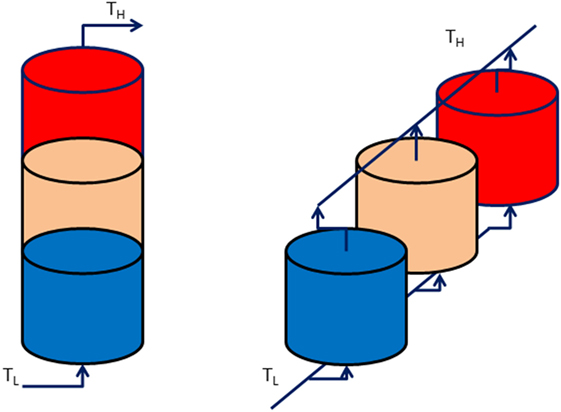
Figure 5. Thermal stratification could be enhanced by using multi-segment tanks (left) or multiple modular tanks in series or in parallel (right).
Multiple modular tanks put in parallel or in series is also an effective solution to improve stratification. Dickinson et al. (2014) studied the charging and discharging sequences for modular multi-tanks applied in solar thermal hot water system. Three modular tanks with a volume of 270 L each are connected to a heat source simulating a solar collector through immersive coil heat exchangers. Experiments and simulations are both realized in a basis of 2 days. Regarding discharging, it is found that the strategy of discharging in series should be avoided since it results in significant turbulent mixing thus de-stratification in all tanks. Concerning charging process, parallel configuration may evoke de-stratification at the end of the day, when the charging temperature drops lower than that of the inlet region. Although the best strategy seems to be that of charging in series and discharging in parallel, authors concluded by simulation that both parallel configuration for both charging and discharging increase the availability of hot water. Total system efficiency for the solar hot water production system could also be increased.
Heat Conduction Enhancement in BTES
In BTES, the main component is borehole heat exchanger, usually in the form of double-U or other. The storage medium is soil or rock, whose thermal properties are hard to be modified except during the site choosing step. Main PI efforts are on heat conduction enhancement with the aim of reducing overall heat resistance.
Despite different pipe configurations, four layers are generally to be considered for the thermal resistance network: HTF (water, convection), pipe wall (HDPE), borehole (bentonite or cement), and finally ground. According to Delaleux et al. (2012), the borehole grouting resistance is the main one that should be reduced. Generally used grouting materials are cement or bentonite, both of them could be improved by adding conductive aggregates.
Borinaga-Treviño et al. (2013) studied the effects of adding different aggregates in pure cement as grouting materials in vertical buried pipe geothermal heat exchangers. The configuration is the closed loop double-U type heat collector, with a borehole diameter of 140 mm and pipe diameter of 32 mm in exterior and 26 mm interior. Compared with pure cement grout, an addition of silica sand by 66%wt (weight ratio of silica, superplasticizer, and water being 3, 0.02, and 0.54, with respective to cement) provides higher effective heat conductivity (2.1 W/m K instead of 0.8 W/m K). This improvement means either a length reduction for exchanger pipes or an improvement of heat exchange rate, both in the order of 18%.
Adding other functional aggregates such as graphite particles seems to be more effective in heat conduction enhancement. Delaleux et al. (2012) tested two types of graphite composites: flakes and expanded natural graphite worms. A target conductivity value of 5 W/m K could be achieved either by adding 10–15%wt of graphite particle with a mean size of 300 µm or by incorporating 5%wt of conductive-expanded natural graphite with a density of 100 kg/m3. Analytical estimations show that compared with the standard bentonite grout whose conductivity is 2.3 W/m K, graphite-enhanced grout could be 33% more efficient (as shown in Figure 6). This means a size reduction of 33% if keeping the same dimensioning heat transfer rate.
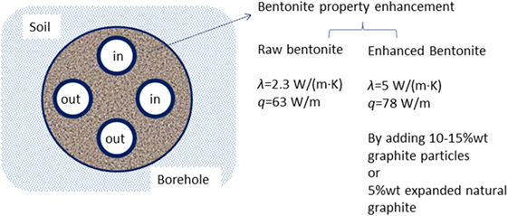
Figure 6. Heat conduction enhancement of grouting materials used in borehole double-U heat exchangers by graphite additives (particles and natural worm) could reduce pipe length and increase heat transfer rate. Data adapted from Delaleux et al. (2012).
Heat Transfer Enhancement in Latent TES
Latent TES using PCM has two main advantages: high-storage capacity and stabilized working temperature. A wide range of storage temperatures are available depending on selected materials. However, latent TES systems are often limited by general low-thermal conductivity of PCM. And this leads to low-heat transfer rate as well as longer charging and discharging time.
Attentions of PI lie in the heat transfer enhancement between PCM and HTF. Factors that affect heat transfer include heat transfer area, PCM thermal conductivity, temperature difference between PCM and HTF, and natural convection. Generally studied heat transfer enhancement measures include the following (illustrated in Figure 7): (i) geometry optimization, including increasing surface-to-volume ratio by encapsulation, direct-contact storage to reduce the influence of low conductivity and (ii) property improvement of PCM by filling high-thermal conductive additive. In addition, the appropriate use of multiple PCMs is a promising technique.
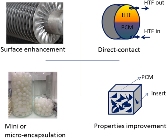
Figure 7. Heat transfer enhancements by geometry optimization and property improvement in phase change material (PCM) thermal storage.
Heat Transfer Surface Enhancement
Adding fins is an effective method to increasing the heat transfer surface for the HTF side. Rathod and Banerjee (2015) studied experimentally the performance enhancement by adding external longitudinal fins in a shell-and-tube heat exchanger TES system. The melting time reduced by 12.5% for a fluid inlet temperature 80°C and by 24.52% for the case of 85°C. Regarding the solidification process, up to 43.6% reduction in time is observed. Castell et al. (2008) confirmed the effect of fins in the enhancement of heat transfer when the outside HTF is immobile, i.e., natural convective heat exchange.
Designing special forms other than multi-tube storage is also a solution. Languri et al. (2013) designed a latent TES by putting PCM in corrugated enclosures where the surface-to-volume ratio is enhanced significantly. Their experimental results show faster charging and discharging process. Thermal response rates of studied enclosure are 9.3 times faster in charging (0.13°C/s compared with 0.014°C/s) and 5.2 times in discharging process than multi-tube structure.
Another enhancement measure other than adding fins is the use of lessing rings for better surface contact. Velraj et al. (1999) tried the effect of filling lessing rings of diameter 1 cm with PCM by 20 vol% in a storage tube. They tested the solidification (discharging) process. Results show that compared with pure PCM tube, the discharging time after lessing ring addictive is nine times shorten.
Finally, integrating PCM modules directly into a hot water tank is a cost-effective solution resolving the issue of low charging or discharging power. In the study of Ibáñez et al. (2006), two PCM blocks are positioned in the upper end of a hot water tank. This combination of sensible and latent storage, named water–PCM tank, is validated by both numerical and experimental results. Applying the combined tank into a solar thermal project, they show a higher solar fraction, thanks to the water–PCM tank storage. Similar studies on the integration of hydrated salt PCM in a cylindrical water tank can be found in Mazman et al. (2009) and Gupta et al. (2014).
Direct-Contact Storage
To eliminate the thermal resistance between HTF and PCM, direct-contact systems have been proposed. In such a system, the HTF flows directly inside the PCM. Main investigations are addressed to perform comparison as well as the natural convection inside molten liquid PCM during charging and discharging. Wang et al. (2014) and Guo et al. (2013) experimentally compared two configurations (direct and indirect) by charging and discharging rate. Their results confirm that the direct-contact TES system could attain a charging power of 2,278 W, three times higher than that of indirect-contact system. The latter, tested by multi-tube heat exchanger, gives a discharge power of 680 W under the same condition. Improved charging and discharging rate makes direct-contact TES system more flexible.
Property Improvement by Material Composition
Similar to the property modification to grouting materials used in geothermal heat exchanger, conductivity enhancement by using PCM composites has been studied extensively. Generally used additives include micro- or nanoparticles (metal, metal oxide, or graphite), fibers, and porous metal matrix.
Oya et al. (2012, 2013) compared thermal performances of different composites using Erythritol as the base PCM. First, nickel matrix with its porosity higher than 90% and porous size of 100–500 µm is impregnated with Erythritol under vacuum environment. The highest obtained effective conductivity is 11.6 W/m K, which is 16 times that of pure Erythritol in solid state, i.e., 0.733 W/m K. Later, three cheaper microparticle additives—spherical graphite, expanded graphite, and nickel nanoparticle, with their average sizes between 5 and 8 µm—are investigated with similar approaches. Results show that the conductivity of Erythritol could be increased by 6.4 times with an addition of 15 vol% of expansion graphite. The same effect, as summarized in Figure 8, could be realized by around 32 vol% of spherical graphite or by 38 vol% addition of micro nickel particles.
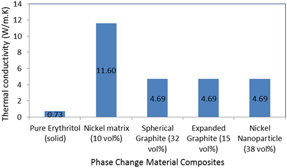
Figure 8. Effective thermal conductivity of phase change composites with nickel matrix, spherical graphite, expanded graphite, and nickel particle [data reported by Oya et al. (2013)].
The heat conductivity in liquid form, however, should be also taken into account. According to Wang et al. (2014), the effect of heat conductivity improvement may be different before and after phase change, especially for the case of nanoparticle addition (TiO2 in this case) when higher concentrated nanoparticles may have the tendency to be agglomerated by surface force. Moreover, for the case of high-concentration addition, accompanied changes might happen to phase change temperature, heat capacity, etc. These properties should also be taken into account in future research.
Encapsulation
Encapsulation of PCMs in mini- or micro-enclosures made of a solid shell is an effective compromise between direct and indirect systems. The envelop serves both as a protection for the PCM during melting and solidification process, and as the heat transfer interface. Main studies are carried out on the size of encapsulation, its shape, as well as different shell materials.
El Omari et al. (2011) analyzed the melting process of PCM within five different enclosures of different aspect ratio. Their simulation considers natural convection in liquid part. Results show more rapid melting in vertical capsules where natural convection is enhanced upward. However, according to the authors, solidification process should also be analyzed to obtain an optimal configuration. Wei et al. (2005) studied the discharging (solidification of PCM) character with four different capsules: sphere, cylinder, plate, and tube. Both experimental and simulation results show better heat release rate from the spherical capsules. In contrary, the tubular shape seemed to be the worst choice.
Compared with direct-contact system, encapsulated PCM particles have lower charging and discharging rate due to shell thermal resistance. Besides preparing PCM capsules as small as possible to attain higher A/V ratio, another interesting technique is the design of laminated heat conduction board used to fix PCM capsules. Darkwa and Su (2012) investigated by simulation a composite high-conductivity laminated board. In such a board, microencapsulated PCM particles (50 vol%) are fixed in copper foam (1 vol%) by conductive adhesive (49 vol%). The arrangements of particles are controllable, thanks to which a comparative study is possible for three different configurations: rectangular, triangular, and pyramidal. Results show more than 10 times higher effective thermal conductivity for all three studied PCM boards (~2.2 W/m K with the rectangular slightly higher) than that of pure PCM (0.2 W/m K). However, one limitation of such a design is its reduced thermal storage density: compared with pure PCM, which has an energy storage density of 157 MJ/m3, microencapsulate PCM board provides only 81 MJ/m3.
Other issues, such as durability with thermal cycle, compromise between the heat conductivity and energy density should be addressed in future research.
Multiple PCM Arrangement
The charging and discharging rate can be intensified by using several PCMs with different melting temperatures. During charging process, by arranging PCMs with decreasing melting temperatures along the hot HTF flow direction, the temperature difference between the HTF outlet and the PCM is high. Similar effect can be obtained by placing increasing melting point PCMs along the flow direction of cold HTF during discharging.
The research group from Zhejiang University conducted several investigations on the utilization of multiple PCM in TES. For example, Wang et al. (2001) studied three PCMs radically arranged around a copper tube. The three PCMs have their melting points of 64.2, 55.5, and 41.8°C, respectively, and they are configured in the order of exterior to interior. By charging those PCMs with hot water at 70°C, it is found that the total melting time for multiple PCMs is 21% shorter than single PCM with melting point of 55.5°C. Similar results are obtained later by Fang and Chen. (2007), who arranged three PCMs in the longitudinal direction of the HTF tube.
Heat and Mass Transfer Enhancement in Sorption TES
In thermochemical TES, energy storage happens by physical or chemical sorption. Solid–gas adsorption or liquid–gas absorption processes are suitable for low-temperature storage. Chemical reactions using salt hydrates are usually suitable for medium- or high-temperature application due to higher regeneration temperature.
Two main characteristics should be considered for sorption TES systems: the density of energy storage and the specific power of energy discharging. First, the density of storage, from the material point of view, is generally 10 times higher than sensible water storage. From the system point of view, however, this will become smaller due to auxiliary equipment such as reactor bed, HTF tubing, etc. The auxiliary volume should be reduced to keep a high-storage density. Second, especially for the discharging process, the specific discharging power depends on the reaction rate, which in turn depends on the mass transfer between solid and gas, a better control of reaction condition, etc.
For above reasons, heat transfer between HTF and sorbents, as well as mass transfer inside the reactor bed, are main directions of PI. Principal approaches include the following: (i) reactor bed optimization for a better solid filling rate by using conductive porous material; (ii) mass transfer enhancement for a better contact between solid and gas; and (iii) heat transfer enhancement for more precise control over reaction conditions. Here, we will give several new ideas without covering all studies. Readers are advised to refer to recent reviews by Cot-Gores et al. (2012), Kiplagat et al. (2012), and Yu et al. (2013) for exhaustive information.
Progresses in Absorption Systems
Only recently, absorption systems begin to be used in TES since major attentions have been addressed to their cooling applications. Three advancements worth to be mentioned are as follows: the introduction of new working pairs for heat storage, expanded three-phase cycles, and integrated sensible-absorption storage.
NaOH–water liquid pair is investigated by Weber, Empa, Switzerland (Bales et al., 2008) under the international project IEA SHC Task 32. They tested a one stage closed absorption system with a driving temperature of 95°C. Their results estimate that if using two-stage absorption with hot side temperature as high as 150°C, the energy storage density could be as high as 250 kWh/m3.
Under the same IEA project, Bales in SERC, Sweden, reported experimental results of a patented cycle called thermochemical accumulator. During the charging process, LiCl salt solution first becomes concentrated; approaching the saturated point, then it appears the crystallization to form salt crystals. With a charging temperature of 95°C, the energy storage density is verified to be 253 kWh/m3, 3.6 times higher than that of sensible storage by water for a 60°C temperature rise.
Quinnell and Davidson. (2012b, 2014) proposed an integrated TES system (Figure 9) where absorption and desorption of liquid CaCl2 solution with water happens in a single vessel. An immersive heat exchanger enables the charging and discharging processes without disturbance to the temperature and concentration stratification inside the tank. Their results show promising storage density: with a well-insulated 4 m3 storage tank and a charging temperature of 95°C maximum, the estimated storage time constant is 160 days. This duration is sufficient for seasonal house heating.
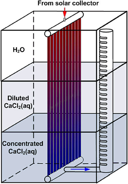
Figure 9. Advancements in absorption process used in thermal energy storage: integrated single-tank design. [Adapted from Quinnell and Davidson. (2012a), permission obtained under Creative Commons license CC BY-NC-ND license.]
Reactor Bed Optimization for Solid–Gas Processes
Porous reaction bed with enhanced adsorbent conductivity could improve charging/discharging rate.
First, optimal solid particles (grains) including their size and shape could increase energy storage density and specific power. Michel et al. (2012) studied two different grains of SiBr2 used in hydration with water vapor. Smaller grains with their size around 50 µm are compared with bigger ones around 80 µm. They tested the hydration process by circulating moist air through the reactor bed. A faster reaction rate is observed for bigger grains than that of smaller ones. It is observed that 191 h after the start of reaction, larger grains have already finished 86% of the total reaction, while that of the smaller grains are only 26%.
Then, adding conductive additives is also an enhancement measure. Carbon fiber has been used to increase effective particle conductivity, which results in higher reaction rate. Special attention, according to Nakaso et al. (2004), should be taken in that both heat transfer coefficient and the conductivity should be considered.
Finally, enhanced mass transfer with better gas diffusion inside reactor bed is helpful for the charging/discharging. Michel et al. (2012) used special gas diffuser outside of the gas inlet [illustrated by Figure 10, adapted from Michel et al. (2012)] and compared its effect on discharging. Results show that compared with another reactor without gas diffuser, the improved reactor provides a higher discharging power by 12.5%, under given reaction advancement.
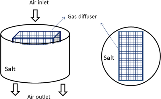
Figure 10. Gas diffuser can optimize solid–gas mass transfer, which determines the discharging rate of thermochemical thermal energy storage.
Heat Exchanger Adaptation and Utilization of Heat Pipe
Coated heat exchanger that brings closer the reactor surface and sorption material increases the heat transfer coefficient and thus results in higher system charging or discharging rate. Various coating methods enable uniform adsorbent layer outside a tube or a plate. Higher specific power is generally achieved, although studies are still being done regarding coating stability after several cycles as well as the influence of layer thickness.
Moreover, appropriate incorporation of heat pipe between reactor surface and HTF can improve system performance. Related studies have been reported by Wang et al. (2006).
Conclusion
Flexible, efficient, and compact TES systems are key elements for future sustainable heating networks. To achieve these features, researches can be inspired by different PI approaches reviewed in this article. Principal research topics are summarized as follows.
Sensible TES
Stratification could be enhanced by different techniques, which are in general beneficial for better availability of thermal energy. Higher system efficiency is expected through the use of low-flow inlet flow diffuser, thermal diodes, etc. Apart from these stratifying devices, the H/d ratio should also be considered. In general, for storage of several hours where heat loss is insignificant, higher H/d ratio (3–5) should be used to maintain the usability of energy. This is the case for most buffer storages as well as home water tanks. However, for long-term sensible storages, the best H/d ratio is 1 from the point of view of heat loss minimization. Consequently, a compromise should be made in terms of H/d ratio between values higher than 1 (better stratification) and near 1 (better heat conservation). In addition, arranging multiple modular tanks in parallel is an effective solution to avoid the mixing of hot and cold fluids.
Latent TES
Phase change material as a storage medium generally shows higher compactness than sensible TES. However, research efforts are still to be made in improving PCM thermal conductivity and heat transfer during charging or discharging processes. Two surface/volume ratios—one between outer insulation surface and storage volume and the other between inner heat transfer surface and storage volume—are crucial influencing parameters on system performance. For PCM storage, attention should be made on the difference between real system volume and effective storage volume, the latter representing merely the volume of PCM. Composite materials with conductive additives have shown enhanced thermal properties. Encapsulation or direct systems seem to be promising, thanks to their higher discharging rate. R&D efforts should also focus on the modular design to facilitate extensive applications of PCM TES in practical projects.
Thermochemical TES
Thermochemical TES is promising, thanks to its high-energy storage density and its zero storage loss during long-term storage. This technology, still under the phase of basic research, requires combined efforts among process engineering specialists, chemists, and thermal engineers. PI methods such as compact heat exchanger–reactor design and the application of heat pipe may make thermochemical TES an industrialized product in the future.
Author Contributions
XG contributed to the overall organization, relecture and research work of the manuscript. AG participated in the stratification part (see Successful PI Applications in TES).
Conflict of Interest Statement
The authors declare that the research was conducted in the absence of any commercial or financial relationships that could be construed as a potential conflict of interest.
Funding
This study is partially supported by EFFICACITY, a French R&D Institute for Energy Transition in Cities. Special thanks go to Dr. Shuai Deng from Tianjin University for his valuable advices.
References
Altuntop, N., Arslan, M., Ozceyhan, V., and Kanoglu, M. (2005). Effect of obstacles on thermal stratification in hot water storage tanks. Appl. Therm. Eng. 25, 2285–2298. doi: 10.1016/j.applthermaleng.2004.12.013
Bales, C., Gantenbein, P., Jaenig, D., Kerskes, H., Summer, K., Van Essen, M., et al. (2008). Laboratory Tests of Chemical Reactions and Prototype Sorption Storage Units, A Report of IEA Solar Heating and Cooling programme – Task 32. Borlänge: Solar Energy Research Center SERC.
Borinaga-Treviño, R., Pascual-Muñoz, P., Castro-Fresno, D., and Del Coz-Díaz, J. J. (2013). Study of different grouting materials used in vertical geothermal closed-loop heat exchangers. Appl. Therm. Eng. 50, 159–167. doi:10.1016/j.applthermaleng.2012.05.029
Bouhdjar, A., and Harhad, A. (2002). Numerical analysis of transient mixed convection flow in storage tank: influence of fluid properties and aspect ratios on stratification. Renew. Energy 25, 555–567. doi:10.1016/S0960-1481(01)00090-8
Brown, N. M., and Lai, F. C. (2011). Enhanced thermal stratification in a liquid storage tank with a porous manifold. Sol. Energy 85, 1409–1417. doi:10.1016/j.solener.2011.03.024
Castell, A., Solé, C., Medrano, M., Roca, J., Cabeza, L. F., and García, D. (2008). Natural convection heat transfer coefficients in phase change material (PCM) modules with external vertical fins. Appl. Therm. Eng. 28, 1676–1686. doi:10.1016/j.applthermaleng.2007.11.004
Cot-Gores, J., Castell, A., and Cabeza, L. F. (2012). Thermochemical energy storage and conversion: a-state-of-the-art review of the experimental research under practical conditions. Renew. Sustain. Energy Rev. 16, 5207–5224. doi:10.1016/j.rser.2012.04.007
Darkwa, J., and Su, O. (2012). Thermal simulation of composite high conductivity laminated microencapsulated phase change material (MEPCM) board. Appl. Energy 95, 246–252. doi:10.1016/j.apenergy.2012.02.062
Delaleux, F., Py, X., Olives, R., and Dominguez, A. (2012). Enhancement of geothermal borehole heat exchangers performances by improvement of bentonite grouts conductivity. Appl. Therm. Eng. 3, 92–99. doi:10.1016/j.applthermaleng.2011.09.017
Devore, N., Yip, H., and Rhee, J. (2013). Domestic hot water storage tank: design and analysis for improving thermal stratification. J. Sol. Energy Eng. Trans. ASME 135, 171–178. doi:10.1115/1.4025517
Dickinson, R. M., Cruickshank, C. A., and Harrison, S. J. (2014). Thermal behaviour of a modular storage system when subjected to variable charge and discharge sequences. Sol. Energy 104, 29–41. doi:10.1016/j.solener.2013.09.038
Eames, P. C., and Norton, B. (1998). The effect of tank geometry on thermally stratified sensible heat storage subject to low Reynolds number flows. Int. J. Heat Mass Transf. 41, 2131–2142. doi:10.1016/S0017-9310(97)00349-9
El Omari, K., Kousksou, T., and Le Guer, Y. (2011). Impact of shape of container on natural convection and melting inside enclosures used for passive cooling of electronic devices. Appl. Therm. Eng. 31, 3022–3035. doi:10.1016/j.applthermaleng.2011.05.036
Fan, J., and Furbo, S. (2012a). Buoyancy driven flow in a hot water tank due to standby heat loss. Sol. Energy 86, 3438–3449. doi:10.1016/j.solener.2012.07.024
Fan, J., and Furbo, S. (2012b). Thermal stratification in a hot water tank established by heat loss from the tank. Sol. Energy 86, 3460–3469. doi:10.1016/j.solener.2012.07.026
Fang, M., and Chen, G. (2007). Effects of different multiple PCMs on the performance of a latent thermal energy storage system. Appl. Therm. Eng. 27, 994–1000. doi:10.1016/j.applthermaleng.2006.08.001
Goumba, A., Chiche, S., Guo, X., Colombert, M., and Bonneau, P. (2017). “Recov’Heat: an estimation tool of urban waste heat recovery potential in sustainable cities,” in AIP Conference Proceedings. Paris.
Guo, S., Li, H., Zhao, J., Li, X., and Yan, J. (2013). Numerical simulation study on optimizing charging process of the direct contact mobilized thermal energy storage. Appl. Energy 112, 1416–1423. doi:10.1016/j.apenergy.2013.01.020
Gupta, A., Mathie, R., and Markides, C. N. (2014). An experimental and computational investigation of a thermal storage system based on a phase change material: heat transfer and performance characterization. Comput. Therm. Sci. An Int. J. 6. doi:10.1615/.2014011117
Hadorn, J. C. (2008). “Advanced storage concepts for active solar energy – IEA SHC Task 32 2003-2007,” in Eurosun – 1st Int Conf Sol heating Cool Build, Lisbon. 1–8.
Han, Y. M., Wang, R. Z., and Dai, Y. J. (2009). Thermal stratification within the water tank. Renew. Sustain. Energy Rev. 13, 1014–1026. doi:10.1016/j.rser.2008.03.001
Ibáñez, M., Cabeza, L. F., Solé, C., Roca, J., and Nogués, M. (2006). Modelization of a water tank including a PCM module. Appl. Therm. Eng. 26, 1328–1333. doi:10.1016/j.applthermaleng.2005.10.022
Kiplagat, J. K., Wang, R. Z., Li, T. X., and OLIVEIRA, R. G. (2012). Enhancement of heat and mass transfer in solid gas sorption systems. Int. J. Air Cond. Refrig. 20, 1130001. doi:10.1142/S2010132511300011
Languri, E. M., Aigbotsua, C. O., and Alvarado, J. L. (2013). Latent thermal energy storage system using phase change material in corrugated enclosures. Appl. Therm. Eng. 50, 1008–1014. doi:10.1016/j.applthermaleng.2012.07.012
Lund, H., Werner, S., Wiltshire, R., Svendsen, S., Thorsen, J. E., Hvelplund, F., et al. (2014). 4th Generation District Heating (4GDH): integrating smart thermal grids into future sustainable energy systems. Energy 68, 1–11. doi:10.1016/j.energy.2014.02.089
Mazman, M., Cabeza, L. F., Mehling, H., Nogues, M., Evliya, H., and Paksoy, H. O. (2009). Utilization of phase change materials in solar domestic hot water systems. Renew. Energy 34, 1639–1643. doi:10.1016/j.renene.2008.10.016
Mehling, H., Hippeli, S., Hiebler, S., and Cabeza, L. F. (2003). PCM-module to improve hot water heat stores with stratification. Renew. Energy 28, 699–711. doi:10.1016/S0960-1481(02)00108-8
Michel, B., Mazet, N., Mauran, S., Stitou, D., and Xu, J. (2012). Thermochemical process for seasonal storage of solar energy: characterization and modeling of a high density reactive bed. Energy 47, 553–563. doi:10.1016/j.energy.2012.09.029
Nakaso, K., Anai, M., Sasaki, Y., Hamada, Y., and Fukai, J. (2004). “Improvement of heat transfer characteristic in a solid-gas thermochemical reactor,” in 10th APCChE, 2G-07 (Kitakyushu, Japan).
Oya, T., Nomura, T., Okinaka, N., and Akiyama, T. (2012). Phase change composite based on porous nickel and erythritol. Appl. Therm. Eng. 40, 373–377. doi:10.1016/j.applthermaleng.2012.02.033
Oya, T., Nomura, T., Tsubota, M., Okinaka, N., and Akiyama, T. (2013). Thermal conductivity enhancement of erythritol as PCM by using graphite and nickel particles. Appl. Therm. Eng. 61, 825–828. doi:10.1016/j.applthermaleng.2012.05.033
Quinnell, J. A., and Davidson, J. H. (2012a). Distributed solar thermal: innovations in thermal storage. Annu. Rev. Heat Transf. 15. doi:10.1615/AnnualRevHeatTransfer.20
Quinnell, J. A., and Davidson, J. H. (2012b). Mass transfer during sensible charging of a hybrid absorption/sensible storage tank. Energy Procedia 30, 353–361. doi:10.1016/j.egypro.2012.11.042
Quinnell, J. A., and Davidson, J. H. (2014). Heat and mass transfer during heating of a hybrid absorption/sensible storage tank. Sol. Energy 104, 19–28. doi:10.1016/j.solener.2013.07.035
Rathod, M. K., and Banerjee, J. (2015). Thermal performance enhancement of shell and tube latent heat storage unit using longitudinal fins. Appl. Therm. Eng. 75, 1084–1092. doi:10.1016/j.applthermaleng.2014.10.074
Smith, H., Bell, S. S., Macbeth, J. N., Christie, D. C., and Finlayson, N. (2010). “CFD analysis of a density-dependent valve within a hot water system,” in V European Conference on Computational Fluid Dynamics ECCOMAS CFD. Lisbon.
Velraj, R., Seeniraj, R. V., Hafner, B., Faber, C., and Schwarzer, K. (1999). Heat transfer enhancement in a latent heat storage system. Sol. Energy 65, 171–180. doi:10.1016/S0038-092X(98)00128-5
Wang, J., Ouyang, Y., and Chen, G. (2001). Experimental study on charging processes of a cylindrical heat storage employing multiple-phase-change materials. Int. J. Energy Res 25, 439–447. doi:10.1002/er.695
Wang, L. W., Wang, R. Z., Lu, Z. S., and Chen, C. J. (2006). Studies on split heat pipe type adsorption ice-making test unit for fishing boats: choice of heat pipe medium and experiments under unsteady heating sources. Energy Convers. Manag. 47, 2081–2091. doi:10.1016/j.enconman.2005.12.020
Wang, W., Guo, S., Li, H., Yan, J., Zhao, J., Li, X., et al. (2014). Experimental study on the direct/indirect contact energy storage container in mobilized thermal energy system (M-TES). Appl. Energy 119, 181–189. doi:10.1016/j.energy.2014.01.054
Wei, J., Kawaguchi, Y., Hirano, S., and Takeuchi, H. (2005). Study on a PCM heat storage system for rapid heat supply. Appl. Therm. Eng. 25, 2903–2920. doi:10.1016/j.applthermaleng.2005.02.014
Yu, N., Wang, R. Z., and Wang, L. W. (2013). Sorption thermal storage for solar energy. Prog. Energy Combust. Sci. 39, 489–514. doi:10.1016/j.pecs.2013.05.004
Keywords: process intensification, thermal energy storage, thermal stratification, phase change material, heat transfer enhancement
Citation: Guo X and Goumba AP (2018) Process Intensification Principles Applied to Thermal Energy Storage Systems—A Brief Review. Front. Energy Res. 6:17. doi: 10.3389/fenrg.2018.00017
Received: 26 July 2017; Accepted: 05 March 2018;
Published: 20 March 2018
Edited by:
Rangan Banerjee, Indian Institute of Technology Bombay, IndiaReviewed by:
Zhenjun Ma, University of Wollongong, AustraliaChristos N. Markides, Imperial College London, United Kingdom
Copyright: © 2018 Guo and Goumba. This is an open-access article distributed under the terms of the Creative Commons Attribution License (CC BY). The use, distribution or reproduction in other forums is permitted, provided the original author(s) and the copyright owner are credited and that the original publication in this journal is cited, in accordance with accepted academic practice. No use, distribution or reproduction is permitted which does not comply with these terms.
*Correspondence: Xiaofeng Guo, eGlhb2ZlbmcuZ3VvQGVzaWVlLmZy