- 1Department of Chemistry, School of Science, Wuhan University of Technology, Wuhan, China
- 2Department of Chemistry, University of Massachusetts Boston, Boston, MA, USA
A highly ordered mesoporous carbon (HOMC) has been synthesized through a strongly acidic, aqueous cooperative assembly route. The structure and morphology of the carbon material were investigated using TEM, SEM, and nitrogen adsorption–desorption isotherms. The carbon was proven to be meso-structural and consisted of graphitic micro-domain with larger interlayer space. Active carbon impedance and electrochemical measurements reveal that the synthesized highly ordered mesoporous carbon (HOMC) exhibits a promoted electrochemical hydrogen insertion process and improved capacitance and hydrogen storage stability. The meso-structure and enlarged interlayer distance within the HOMC are suggested as possible causes for the enhancement in hydrogen storage. Both hydrogen capacity in the carbon and mass diffusion within the matrix were improved.
Introduction
Hydrogen is generally regarded as a renewable and pollution-free energy resource; its implementation for energy production could reduce the demand for fossil fuels and thus the emission of greenhouse gases. One of the crucial issues for hydrogen-based energy applications is how to store the hydrogen in a safe and reversible way. Many efforts have been made to cope with this challenge. The use of transition metals and metal alloys as host materials to electrochemically adsorb hydrogen is a widely used method in ambient conditions. However, most of the transition metals used to form metal-hydrides are relatively heavy and expensive. Alternatively, it has been demonstrated that carbon material with light weight and high electronic conductivity can be used to store atomic hydrogen in its interlayers and pores when an aqueous solution was electrolyzed on the cathodic polarized carbon (Frackowiak and Beguin, 2002; Jurewicz et al., 2004; Zuttel et al., 2004; Vix-Guterl et al., 2005; Begin et al., 2006; Qu, 2008). Therefore, carbonaceous materials become a potential candidate for hydrogen storage. Previous studies have shown that different carbonaceous materials can be used for the electrochemical hydrogen storage, such as carbon nanotube (Martin et al., 2010), nitrogen-doped carbon nanotube (Chen et al., 2013), nitrogen and copper functionalized carbon (Kong et al., 2010), nitrogen enriched ordered mesoporous carbon (OMC) (Giraudet et al., 2010), carbon with nitrogen doping (Xia et al., 2009), nitrogen-doped highly ordered mesoporous carbon (HOMC) (Liu et al., 2014), nitrogen-containing porous carbon (Shen and Fan, 2013), carbon nanotube with Ni nanoparticle or nickel boride (Wu et al., 2010; Yang et al., 2010) and activated mesoporous carbon containing nickel (Liu et al., 2010). Among those carbon materials, OMC materials have already been widely used as electrode materials for battery and supercapacitor devices in recent years (Simon and Gogotsi, 2008; Liu et al., 2011). Because of their unique chemical and physical properties, especially ordered pore structure, narrow distribution in pore size, and uniform pore connection, OMC have demonstrated superior electrochemical performance over conventional active carbon (AC) materials. In order to improve the hydrogen storage in carbon materials, a HOMC was synthesized in this study. The structure and morphology of the prepared HOMC were characterized. The electrochemical performance, especially the capacity and stability of electrochemical hydrogen storage in the synthesized HOMC, was also investigated. In order to clarify the effect of HOMC on hydrogen storage, a typical commercial AC was also investigated along with HOMC as a point of comparison. The capacity of electrochemical hydrogen storage in HOMC was found to be more than two times that in the AC. This hydrogen storage enhancement may be attributed to the mesoporous structure as well as the enlarged d002 interlayer space in the HOMC.
Experimental Details
Triblock poly(ethylene oxide)-b-poly(propylene oxide)-b-poly-(ethylene oxide) copolymer, Pluronic P123 (EO20PO70EO20, Mav = 5800) was purchased from Sigma-Aldrich Co., Ltd. Other chemicals were purchased from Sinopharm Chemical Reagent Co., Ltd. All chemicals were used as received without further purification. The preparation of HOMC has been reported elsewhere (Liu et al., 2013). 4.80 g of Triblock poly(ethylene oxide)-b-poly(propylene oxide)-b-poly(ethylene oxide) copolymers Pluronic P123 were dissolved in 60 mL of deionized water and stirred at 50°C for 1 h. Then 2.20 g of resorcinol (R) and 1.40 g of hexamethylenetetramine were dissolved in 40 mL of deionized water. A milk-like solution was obtained after the two solutions were mixed. After stirring for 2 h at room temperature, 21.0 mL of 37 wt.% HCl solution was quickly added to the solution. The mixture was further stirred under reflux condenser at 50°C for 48 h. The yellow solid products were collected by sedimentation separation, filtration, washed with deionized water, and air-dried at room temperature. Finally, the as-made composite was thermally treated at 700°C for 3 h in ultrapure argon atmosphere to obtain the HOMC.
The synthesized HOMC is activated through the procedures reported elsewhere (Lv et al., 2012). First, the mixture of the carbon material and the same amount of KOH pellets were added slowly into ethanol while stirring. After removing the ethanol through evaporation at 60°C under ultrapure argon atmosphere while stirring, the activation was then achieved by heating the sample at 700°C for 90 min in ultrapure argon atmosphere. The resulting mixture, after cooling back to room temperature, was washed thoroughly by 1 M HCl solution and deionized water. Finally, the sample is dried at 100°C for 12 h. Before use, all the carbon materials, including activated HOMC and AC, were reflux-washed with acetone in a Soxhlet extractor for about 24 h to remove any physically bonded surface functional groups. The activated porous carbon powder (85 wt.%) was then mixed with carbon black (10 wt.%) and Teflon suspension (5 wt.% of dry material). After thoroughly mixed, those pastes were left for air dry. The resulting Teflon bonded carbon was rolled into a thin film and then the electrode was punched out of film with geometric surface area of 1 cm2. The disk electrode with an overall mass of 10 mg was then sandwiched between two pieces of nickel foam current collector.
Aqueous potassium hydroxide solution (30 wt.%) was used as an electrolyte in all measurements. An AutoLab electrochemical workstation (PGSTAT100N) was used for impedance measurements. Electrochemical impedance spectroscopy (EIS) was carried out at the frequency region of 0.001 Hz–100 kHz with amplitude of 5 mV. A CH Instruments 660D electrochemical workstation is used for electrochemical measurements. A Hg/HgO reference electrode was used in all measurements. TEM images were taken with a JEM 2100F electron microscope operating at 200 kV. SEM images were taken using a Hitachi S-4800 field emission scanning electron microscope. Powder X-ray diffraction (XRD) patterns were recorded on a Rigaku D/MAX-RB diffractometer with a CuKa radiation operating at 40 kV, 50 mA. A Micromeritics ASAP 2020 porosimeter was used for the surface area and porosity measurements. Nitrogen was used as absorbent gas. Density functional theory (DFT) software from Micromeritics was also used.
Result and Discussion
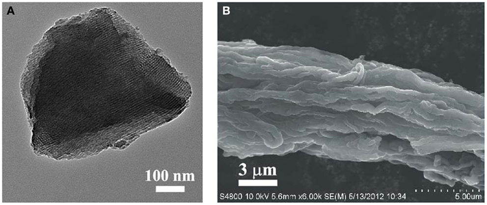
The mesostructure of synthesized HOMC is observed in the TEM image in Figure 1A. The ordered stripe-like patterns presented in the TEM images confirm that the prepared HOMC possesses large domains of highly ordered mesoporous structure. A SEM image of the HOMC is presented in Figure 1B. Rod-like domains were found in the HOMC. Those rod particles were assembled parallel with each other.
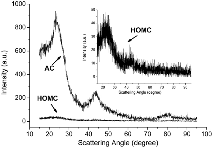
The structure of the HOMC in this study was also investigated by the XRD. Figure 2 shows the XRD patterns for the synthesized HOMC and AC. The (100) and (110) peaks were found to be around 42° and 80°2θ, respectively, which indicated the existence of small domains of ordered graphene sheets. The width of those peaks for the HOMC was broader than those for the AC. This indicated that the AC materials used in this study had relatively large defective graphene layer domains than the HOMC. Since the electrochemically adsorbed hydrogen may diffuse and accommodate into those graphene interlayers, the larger domains of defective graphene layers will result in a relatively longer diffusion length. The interlayer distance between the graphene layers (d002) can be calculated from the scattering angles for (002) peaks by using the Bragg equation. The estimated d-spacing values for HOMC and AC are 0.423 and 0.378 nm, respectively.
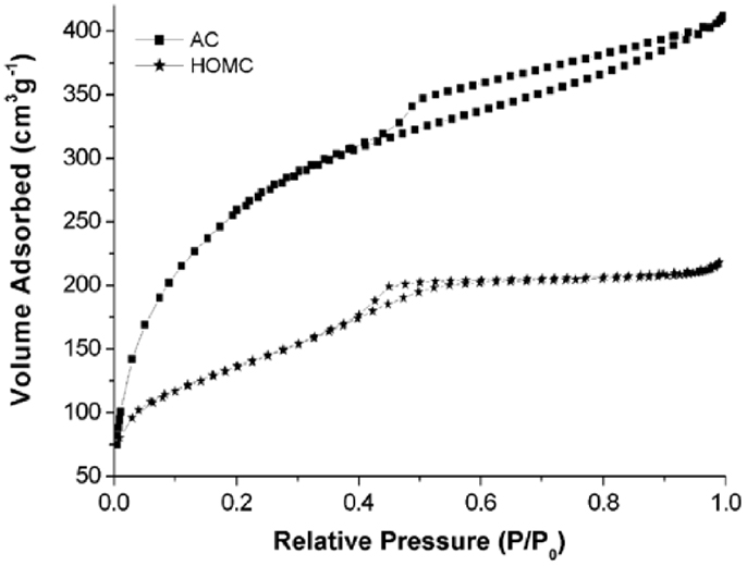
The nitrogen sorption isotherms of both carbon materials are shown in Figure 3. The type-IV curves are observed in the isotherms of the HOMC indicating the formation of mesostructure. Moreover, both isotherms clearly demonstrate hysteresis loops. It is well known that the shape of the hysteresis loops can provide information on the pore structure (Horikawa et al., 2011). As shown in Figure 3, a type-H2 loop, which represents a network of interconnected pores of progressive sizes and shapes, is observed for the HOMC material. The hysteresis loop for AC, however, demonstrated type-H4 hysteresis, which is indicative of material having narrow, slit-shape pores (Horikawa et al., 2011). The surface area of the HOMC and AC used in this study were found to be 894 and 1114 m3 g−1, respectively.
The electrochemical performance studies of the carbon materials were conducted in 30 wt.% potassium hydroxide aqueous solution. Figure 4 shows the cyclic voltammograms (CV) recorded in the potential range of −1.7 to 0.7 V. It is clearly shown that a significant cathodic current, which can be assigned to the hydrogen generation, is observed starting around −1.2 V. It is also noticed in the CV that the double-layer capacitance of HOMC and AC are more or less the same. Since the surface area of AC is larger than that of HOMC, the specific capacitance (Farad per meter) may relate to the carbon structure. It should be noted that, even though all carbon materials have been washed by acetone to remove the most of weakly attached functional groups, and then minimized the contribution from pseudocapacitance. But the shapes of CV, shown in Figure 4, still deviated from perfect double-layer behaviors. This suggests that there exist certain chemical-bonded functional groups on the carbon surface, which may come from the precursors of both synthesized HOMC and AC.
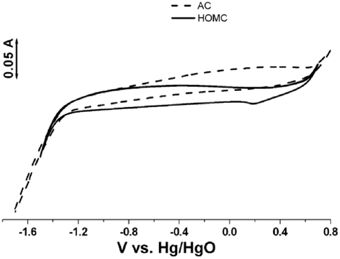
Figure 4. Cyclic voltammograms of the HOMC (solid) and AC (dash) electrode recorded in a three electrode cell at 20 mV s−1 with 30% KOH aqueous solution. Pt mesh is used as counter electrode. Hg/HgO as reference electrode.
Figure 5A shows the discharge profiles of the carbon materials after holding at constant potential of −1.20 V for 3 h in 30 wt.% KOH solution. The discharging curves demonstrated the comparison of the hydrogen electrochemical storage capacities in the HOMC and AC. The hydrogen adsorption capacity in the HOMC and AC was found to be 60.7 and 28.4 mA h g−1, respectively. It demonstrates that the HOMC adsorbed more than two times more hydrogen than the AC. The hydrogen adsorption increase may be attributed to the mesostructure and the enlarged d002 interlayer spacing in the HOMC, which has been suggested in previous studies (Qu, 2008).
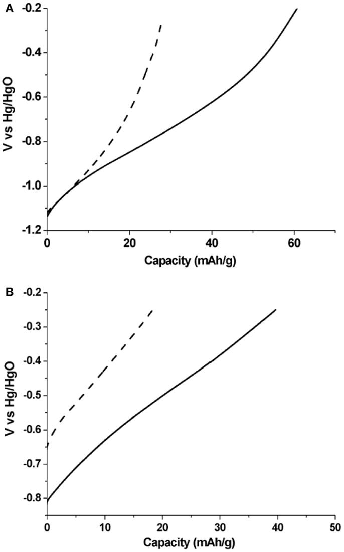
Figure 5. (A) Discharge curves of HOMC (solid) and AC (dash) electrode after holding at constant potential of −1.20 V for 3 h in 30 wt.% KOH solution. (B) Discharge current of both carbon electrodes after 48 h resting at open circuit potential.
The stability of hydrogen stored inside the carbon material was also investigated. After charging, both carbon electrodes were rested in an open circuit potential (OCP) for 48 h. Figure 5B shows the discharged curves of both electrodes after rest. Comparing with the discharging curves in Figure 5A, one can observe the positive shift of the OCPs of both carbon electrodes. But the OCP for the electrode made of AC shifted more than that of HOMC. The OCPs for the HOMC and AC electrodes after rest were −0.82 and −0.65 V, respectively. The OCP relates to the free energy of the H atoms in the carbon matrix, which is determined by the chemical environment of the H atoms. The change of OCP could result from the redistribution of H atoms within the carbon matrix during rest; therefore, the chemical environment would be altered as well. The lesser OCP change for the electrode made with HOMC exemplified the relatively more homogenous porous structure compared to the AC. After resting under OCP for 48 h, about 65% of the initially stored hydrogen remained inside both electrodes.
Active carbon impedance was used to study in detail the electrochemical hydrogen storage process in the HOMC. Figure 6 shows the typical impedance spectra for both carbon materials. There are two distinct sections shown in the Nyquist plot, which are believed to represent the two steps of hydrogen electrochemical-insertion into the carbon materials (Kafle and Qu, 2010; Liu et al., 2014). At high frequency, a semicircle represents the process of atomic hydrogen formation and adsorption on the carbon surface. A straight line presented in the low frequency region stands for the step of hydrogen atoms diffusing into the interlayers of carbon materials. Two different equivalent circuits, shown in Figure 6, were used to simulate each of these two steps. As shown in Figure 6, those two models fit the spectra very well.
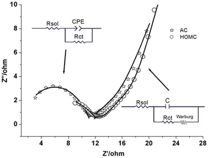
Figure 6. AC impedance spectra for HOMC (✩) and AC (◯) in 30% KOH solution. Insets are the equivalent circuits used for the fitting of the AC impedance spectrum. The equivalent circuit on the left was used to fit the spectrum in the frequency range of 100 kHz to 1 Hz and the one on the right was used for the frequency range of 1–0.001 Hz.
During the first step, a hydrogen from a water molecule gained one electron and under potential deposited (UPD) on the carbon surface. The Faradic process can be characterized by the charge transfer resistance, Rct (Kafle and Qu, 2010). Figure 7A shows the comparison of the change in Rct vs. potential for the two carbon electrodes. Before −1.0 V, the values of Rct for both carbons were similar. Starting from −1.0 V, Rct for AC slowly increased and reached around 80 Ω about −1.15 V, while, the Rct for HOMC stayed low until the potential reached below −1.1 V. A sharp increase of Rct for the HOMC can be observed in the potential range of −1.1 to −1.15 V. The increase of Rct along with the potential could be related to an increase in H coverage, which would gradually reduce the active sites on the electrode surface, while the sudden Rct increase could result from 100% H coverage and drastic H2 evolution. As shown in Figure 7A, the Rct for the HOMC only started to increase at a more negative potential than the AC, the phenomena demonstrated the higher overpotential for H2 evolution on HOMC electrode. The higher overpotential would lead to higher H insertion into the carbon material (Qu, 2008), which is consistent with greater hydrogen storage in HOMC vs. AC.
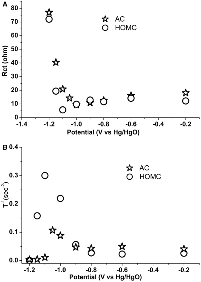
Figure 7. (A) Charge transfer resistance, Rct, and (B) T−1, for HOMC (✩) and AC (◯) electrode in 30% KOH solution with different electrode potential. Rct and Wo-T−1 obtained through fitting the impedance spectra within 100 kHz to 1 Hz and 1–0.001 Hz, respectively.
The process for the insertion of electrosorbed H on the surface into carbon matrix was represented in the low frequency region of the AC impedance spectra. As shown in Figure 7, a finite-length Warburg element is used to represent the H diffusion into the lattice of the carbon electrode. A finite-length Warburg impedance can be expressed as (Liu et al., 2014):
where K = 2K2/D, L is the effective diffusion thickness, and D is the effective diffusion coefficient. Therefore, K−1 should be proportional to the diffusion coefficient assuming similar L. Figure 7B shows the plot of K−1, obtained by means of the least square fitting of the AC impedance spectra within 1–0.001 Hz, vs. the applied potential. The trend shown in Figure 7B is similar to that in Liu et al. (2014). The diffusion coefficients for the two carbon materials were constant until the potential reached about −1.0 V. The diffusion rate for H into carbon material should be proportional to the H concentration gradient between the electrode surface, bulk, and H environment in the carbon structure would have a substantial impact on the diffusion coefficient. The diffusion coefficients were found to continuously increase, reaching a maximum at about −1.1 V. Apparently, the much higher diffusion coefficient for HOMC in the potential region of −1.0 and −1.2 V demonstrates more efficient H insertion into the HOMC material.
In summaries, the advantages HOMC were twofold, thermodynamically the carbon had the domain of layer structure with large interlayer distance (d002), which has proven to accommodate more H (Qu, 2008); kinetically, the ordered mesoporous structure provided effective diffusion path.
Conclusion
A HOMC is prepared and applied for electrochemical hydrogen storage. The electrochemical investigation reveals that HOMC shows an enhanced electrochemical hydrogen storage compared to that in standard AC. The hydrogen storage in HOMC is more than twice that of commercial AC. The stability of the stored hydrogen in HOMC is also found to have improved compared with AC.
Conflict of Interest Statement
The authors declare that the research was conducted in the absence of any commercial or financial relationships that could be construed as a potential conflict of interest.
Acknowledgments
This work was partially supported by the Natural Science Foundation of China (11474226 and 61274135) and Fundamental Research Funds for the Central Universities China 2014-zy-166 and 2014-LX-B1-11. The authors thank Dr. Xiao-Qing Liu for his assistance conducting TEM.
References
Begin, F., Friebe, M., Jurewicz, K., Vix-Guterl, C., Dentzer, J., and Frackowiak, E. (2006). State of hydrogen electrochemically stored using nanoporous carbons as negative electrode materials in an aqueous medium. Carbon N. Y. 44, 2392–2398. doi: 10.1016/j.carbon.2006.05.025
Chen, L., Xia, K., Huang, L., Li, L., Pei, L., and Fei, S. (2013). Facile synthesis and hydrogen storage application of nitrogen-doped carbon nanotubes with bamboo-like structure. Int. J. Hydrogen Energy 38, 3297–3303. doi:10.1016/j.ijhydene.2013.01.055
Frackowiak, E., and Beguin, F. (2002). Electrochemical storage of energy in carbon nanotubes and nanostructured carbons. Carbon N. Y. 40, 1775–1787. doi:10.1016/S0008-6223(02)00045-3
Giraudet, S., Zhu, Z., Yao, X., and Lu, G. (2010). Ordered mesoporous carbons enriched with nitrogen: application to hydrogen storage. J. Phys. Chem. C 114, 8639–8645. doi:10.1021/jp101119r
Horikawa, T., Do, D., and Nicholson, D. (2011). Capillary condensation of adsorbates in porous materials. Adv. Colloid Interface Sci. 169, 40–58. doi:10.1016/j.cis.2011.08.003
Jurewicz, K., Frackowiak, E., and Beguin, F. (2004). Towards the mechanism of electrochemical hydrogen storage in nanostructured carbon materials. Appl. Phys. A 78, 981–987. doi:10.1007/s00339-003-2418-8
Kafle, J., and Qu, D. (2010). Enhancement of hydrogen insertion into carbon interlayers by surface catalytic poisoning. J. Phys. Chem. C 114, 19108–19115. doi:10.1021/jp1064006
Kong, A., Wang, W., Yang, F., Ding, H., and Shan, Y. (2010). In situ synthesis of N and Cu functionalized mesoporous FDU-14 resins and carbons for electrochemical hydrogen storage. Int. J. Hydrogen Energy 35, 7530–7538. doi:10.1016/j.ijhydene.2010.04.164
Liu, D., Xia, L., Qu, D., Lei, J., Li, Y., and Su, B. (2013). Synthesis of hierarchical fiber-like ordered mesoporous carbons with excellent electrochemical capacitance performance by a strongly acidic aqueous cooperative assembly route. J. Mater. Chem. A 1, 15447–15458. doi:10.1039/c3ta13518g
Liu, D., Zheng, D., Wang, L., Qu, D., Xie, Z., Lei, J., et al. (2014). Enhancement of electrochemical hydrogen insertion in N-doped highly ordered mesoporous carbon. J. Phys. Chem. C 118, 2370–2374. doi:10.1021/jp412099y
Liu, H., Wang, J., Wang, C., and Xia, Y. (2011). Ordered hierarchical mesoporous/microporous carbon derived from mesoporous titanium-carbide/carbon composites and its electrochemical performance in supercapacitor. Adv. Energy Mater 1, 1101–1108. doi:10.1002/aenm.201100255
Liu, N., Yin, L., Kang, L., Zhao, X., Wang, C., Zhang, L., et al. (2010). Enhanced electrochemical hydrogen storage capacity of activated mesoporous carbon materials containing nickel inclusions. Int. J. Hydrogen Energy 35, 12410–12420. doi:10.1016/j.ijhydene.2010.08.099
Lv, Y., Zhang, F., Dou, Y., Zhai, Y., Wang, J., Liu, H., et al. (2012). A comprehensive study on KOH activation of ordered mesoporous carbons and their supercapacitor application. J. Mater. Chem. 22, 93–99. doi:10.1039/c1jm12742j
Martin, J. B., Kinloch, I. A., and Dryfe, R. A. W. (2010). Are carbon nanotubes viable materials for the electrochemical storage of hydrogen? J. Phys. Chem. C 114, 4693–4703. doi:10.1126/science.1179773
Qu, D. (2008). Mechanism for electrochemical hydrogen insertion in carbonaceous materials. J. Power Sources 179, 310–316. doi:10.1016/j.jpowsour.2007.12.098
Shen, W., and Fan, W. (2013). Nitrogen-containing porous carbons: synthesis and application. J. Mater. Chem. A 1, 999–1013. doi:10.1021/ja203857g
Simon, P., and Gogotsi, Y. (2008). Materials for electrochemical capacitors. Nat Mater 7, 845–854. doi:10.1038/nmat2297
Vix-Guterl, C., Frackowiak, E., Jurewicz, K., Friebe, M., Parmetier, J., and Beguin, F. (2005). Electrochemical energy storage in ordered porous carbon materials. Carbon N. Y. 43, 1293–1302. doi:10.1016/j.carbon.2004.12.028
Wu, M., Hsu, H., Chiu, H., and Lin, Y. (2010). Fabrication of nickel boride-coated carbon nanotube films by electrophoresis and electroless deposition for electrochemical hydrogen storage. Int. J. Hydrogen Energy 35, 8993–9001. doi:10.1016/j.ijhydene.2010.06.019
Xia, Y., Walker, G. S., Grant, D. M., and Mokaya, R. (2009). Hydrogen storage in high surface area carbons: experimental demonstration of the effects of nitrogen doping. J. Am. Chem. Soc. 131, 16493–16499. doi:10.1021/ja9054838
Yang, C., Li, Y., and Chen, W. (2010). Electrochemical hydrogen storage behavior of single-walled carbon nanotubes (SWCNTs) coated with Ni nanoparticles. Int. J. Hydrogen Energy 35, 2336–2343. doi:10.1016/j.ijhydene.2010.01.007
Keywords: highly ordered mesoporous carbon, electrochemical hydrogen storage, hydrogen storage enhancement, catalytic surface
Citation: Liu D, Zeng C, Tang H, Zheng D, Li R, Qu D, Xie Z, Lei J, Xiao L and Qu D (2014) Electrochemical hydrogen storage in a highly ordered mesoporous carbon. Front. Energy Res. 2:42. doi: 10.3389/fenrg.2014.00042
Received: 16 August 2014; Accepted: 22 September 2014;
Published online: 09 October 2014.
Edited by:
Jie Xiao, Pacific Northwest National Laboratory, USAReviewed by:
Jinping Liu, Central China Normal University, ChinaAli Qajar, Pennsylvania State University, USA
Copyright: © 2014 Liu, Zeng, Tang, Zheng, Li, Qu, Xie, Lei, Xiao and Qu. This is an open-access article distributed under the terms of the Creative Commons Attribution License (CC BY). The use, distribution or reproduction in other forums is permitted, provided the original author(s) or licensor are credited and that the original publication in this journal is cited, in accordance with accepted academic practice. No use, distribution or reproduction is permitted which does not comply with these terms.
*Correspondence: Deyu Qu, Wuhan University of Technology, 122 Luoshi Road, Wuhan, Hubei, China 430070 e-mail:ZGV5dXF1d3VoYW5AMTYzLmNvbQ==;
Deyang Qu, University of Massachusetts Boston, 100 Morrissey Blvd., Boston, MA 02482, USA e-mail:ZGV5YW5nLnF1QHVtYi5lZHU=
 Dan Liu1
 Haolin Tang
 Dong Zheng
 Deyu Qu
 Zhizhong Xie
 Deyang Qu